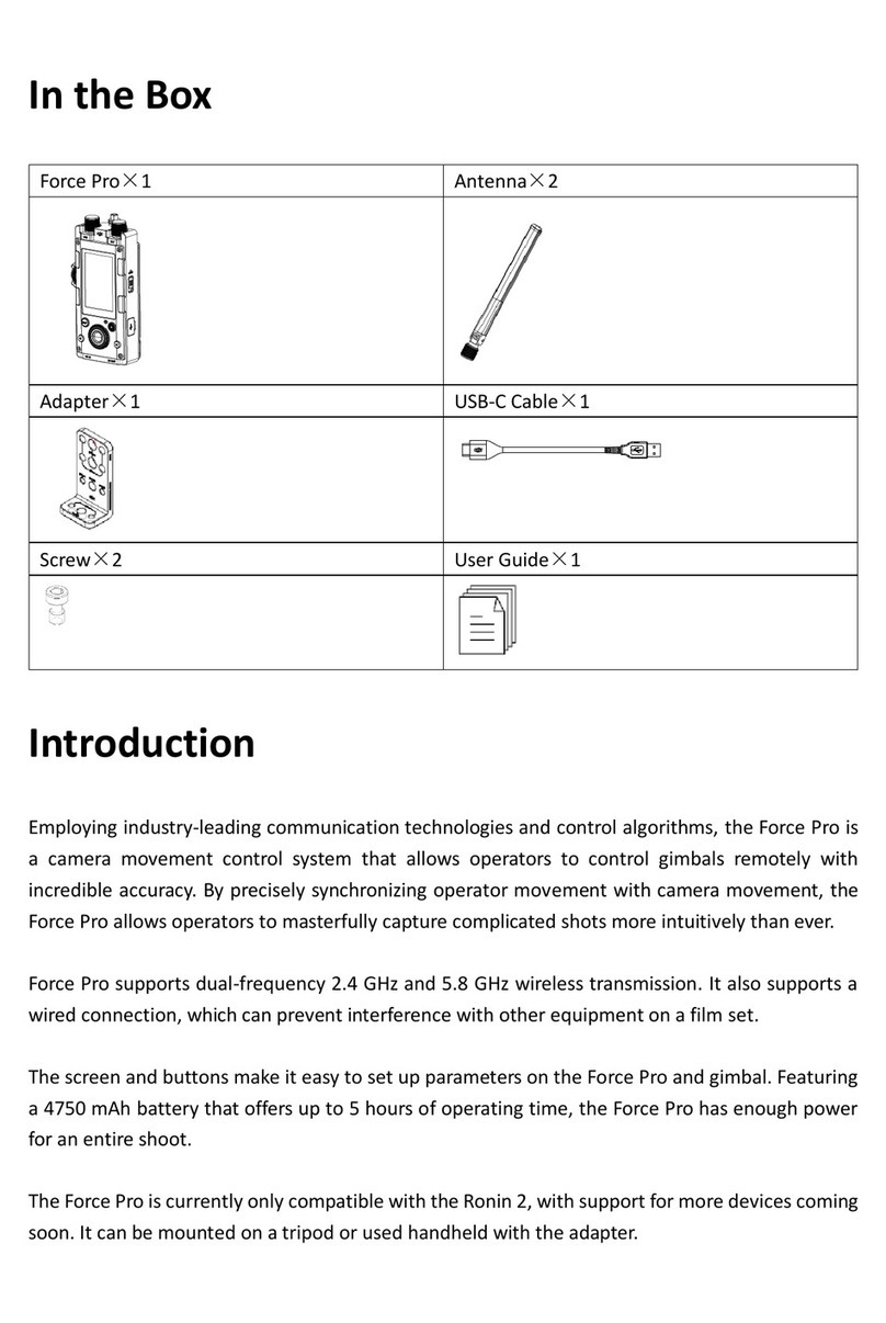
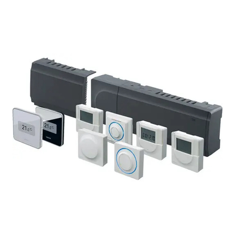
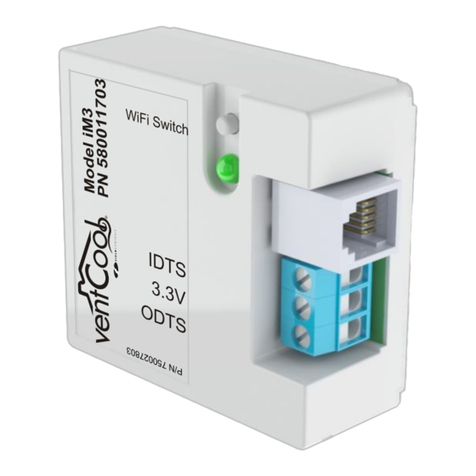
tbs electronics H64 Manual


Wiring control centre installation
In order to ensure the quality of network communication, the master thermostat must be installed in the
living room, in the same area as the router. Please pay attention to distinguish the master and slave
thermostat during the installation.
The master thermostat is packaged with the wiring control centre and named H64-M T WiFi
1. There is a slit above the wiring control centre. Use a small flat-blade screwdriver to insert it and pry
it out and remove the back plate.
Unplug
The
buckle
Pry off the
back plate
06
Product installation and testing

2. Use the back plate to mark the hole position, and then use an impact drill (6mm drill bit) to
make the screw holes (if there is a mounting rail, you can ignore it)
6mm drill bit
07
3. Press the buckle to remove the anti-electrical board, and then connect the wires referring to wiring
port and the marked wiring on the anti-electrical board.
Buckle
Anti-electrical board
08
Sparing

L N LN L N L N L N L N L N L N L N L N L N L N L N L N
Power Pump R1 R2 R3 R4 R5 R6 R7 R8 G1 G2 W1 W2 W3 W4 W5 W6 W7 W8 Cooling
COM NOCOM NO °
C°
C°
C°
C°
C°
C°
C°
CCOM NO
AC
Cooling changeover port
W1-W8:connect to thermostat
lowvoltage, regardless of null
lineandfire line.W1 must
connect with master thermostat
Water pump(Current<5A)
Power supply(100-240VAC 10A)
L:Fire Line N:Null line : Earth line
R1-R8:Connected electric heating actuator
(the total current<5A)
G1、G2:Passive linkage
(can be linked to boiler, heat pump host, mixed water device)
(Current<5A)
Wiring diagram
Wiring control centre H64-CC
Precautions
①W1-W8: Connected to the thermostat, low voltage, regardless of null line and fire line,
W1 must be connected to the master thermostat, W1 corresponds to an area.
② R1-R8: Connected electric heating actuator, R1 corresponds to W1, R2 corresponds to W2, and so on,
R1-R4 can be connected to two electric heating actuators respectively, the total current does not exceed 5A.
15

In order to ensure the quality of network communication, the main thermostat must be installed in the
living room, in the same area as the router. Please pay attention to distinguish the main and slave
thermostats, the main thermostat and wiring control centre are in a package, named H64-MT WiFi
1. Pull back plate to open the thermostat (magnet adsorption)
10
Thermostat quick installation
2. Wiring (It is recommended to use 0.75-1.5mm wire)
Press the snap-gauge
snap-gauge
Insert the wires into slots
11
Connect
NTC10K Power:12V wire from wiring center

3. Fix the back plate with screws
12
4.Cover the fa ce she ll
13


1 2 34567 8
Thermostat heating status: light keep bright with output
without output didn’t light
1 corresponds to the W1 region, and so on
Pump output status: light keep bright with output
without output didn’t bright
heating/cooling changeover status
Cooling mode activate keep bright
Heating mode no bright
Power status: light keep bright
Wiring control centre interface introduction
02

WIFImode
(H64-MT Only)
Cooling
Heating
Programmingmode
Room temperature/
setting temperature
Child lock
Adjust temperature
In switch off status, short press to switch on thermostat.
In switch on status, long press over 5 seconds to switch off; And display OFF.
In power on mode, long press“ + ”and“ - ”button over 5 seconds could enter key lock mode,
and show lock icon. Press “ + ”and“ - ”unlock in lock status.
Up button
Down button
Power button
04


Wakeup
6:00 25°C
Outdoor
8:00 28°C
Back home
11:00 25°C
Outdoor
14:00 28°C
Back home
18:00 25°C 22:00 28°C
Sleep
Wakeup
6:00 20°C
Outdoor
8:00 16°C
Back home
11:00 20°C
Outdoor
14:00 16°C
Back home
18:00 20°C 22:00 16°C
Sleep
(Cooling mode)
(Heating mode)
17
Default programming
S-r:Room temperature
A floor sensor is not present, the unit will be controlled via internal sensor and display as room temperature.
r-F: Dual temperature control
The thermostat will control based on actual room temperature detected by internal sensor and compare the
floor temperature limitation set by parameter 8.If floor temperature higher than limitation, it wil stop working
and alarm E4.If floor sensor is not connected under r-F mode, it will alarm E2.
S-F: Floor temperature control
Thermostat will control via external sensor and display as room temperature.
NTC function selection
z
z
z
z
Verwarmingsmodus

Wiring control centre H64-CC
Power source: 100-240VAC 50 / 60Hz (maximum current 10A)
Storage environment temperature and humidity: -10 ~ 60°C, 0 ~ 90% RH (non-condensing)
Working environment temperature and humidity: 0 ~ 50 °C, 0 ~ 80% RH (non-condensing)
Color: White
Size: 298 X 88 X 64mm
IP rating: IP40
Technical Parameters
88mm
298mm
93.1mm
64mm
01
1 2 34567 8
•
•
•
•
•
•

Wiring control centre H64-CC
Power source: 100-240VAC 50 / 60Hz (maximum current 10A)
Storage environment temperature and humidity: -10 ~ 60°C, 0 ~ 90% RH (non-condensing)
Working environment temperature and humidity: 0 ~ 50 °C, 0 ~ 80% RH (non-condensing)
Color: White
Size: 298 X 88 X 64mm
IP rating: IP40
Technical Parameters
88mm
298mm
93.1mm
64mm
01
1 2 34567 8
* Power supply and signal input: DC12 ~ 18V carrier non-polarity input
(power supply wiring control centre, maximum current 100mA)
* Storage environment temperature and humidity: -10 ~ 60°C, 0 ~ 90% RH (non-condensing)
* Working environment temperature and humidity: 0 ~ 50°C, 0 ~ 80% RH (non-condensing)
* Temperature display range: 0 ~ 50°C
* Display accuracy: 0.1°C
* Color: White
* Size: 86x86x12mm (length * width * thickness)
* Protection level: I P21
* WIFI antenna emission frequency(master controller): 2.4GMHz
* WIF I wireless transmission distance(master controller): 60M in the open area
86mm
86mm
12mm
03
Master(H64-MT WiFi) / Slave(H64-ST)
•
•
•
•
•
•
•
•
•
•
•
* Power supply and signal input: DC12 ~ 18V carrier non-polarity input
(power supply wiring control centre, maximum current 100mA)
* Storage environment temperature and humidity: -10 ~ 60°C, 0 ~ 90% RH (non-condensing)
* Working environment temperature and humidity: 0 ~ 50°C, 0 ~ 80% RH (non-condensing)
* Temperature display range: 0 ~ 50°C
* Display accuracy: 0.1°C
* Color: White
* Size: 86x86x12mm (length * width * thickness)
* Protection level: I P21
* WIFI antenna emission frequency(master controller): 2.4GMHz
* WIF I wireless transmission distance(master controller): 60M in the open area
86mm
86mm
12mm
03
Master(H64-MT WiFi) / Slave(H64-ST)


WiFi Thuis
This manual suits for next models
1
Table of contents
