tbs electronics SHURCut 2500 User manual
®
A Division of General Data Healthcare
Histology Innovation for a NEW Generation
Operator’s Manual
Product Name
Here
SHURCut™ 2500 Microtome
Semi-Automated Rotary Microtome
Catalog #
SC2500
Pub No.: OM SC2500-1
October 2013
SC2500


3 | Page
General Data Healthcare, Inc.
Copyright©2009 General Data Company. All rights reserved
This document may not be copied in whole or in part or reproduced in any other media without the express
written permission of TBS-A Division of General Data Healthcare, or General Data Healthcare. Please note
that under copyright law, copying includes translation into another language.
General Data Healthcare TBS-A Division of General Data Healthcare
Corporate Headquarters 3014 Croasdaile Road
4354 Ferguson Drive Durham, NC 27705
Cincinnati, Ohio 45245 tel. 919-384-9393
Tel. 513-752-7978 Fax. 919-384-9595
Fax.513-965-3636
User Resources and Customer Support
Contact your TBS representative for customer support. For the latest information on TBS products and services,
please visit the TBS website at: www.trianglebiomedical.com.
Scope
This document contains basic information on the use and operation of a SHURCut™ 2500 Microtome and assumes
you have received basic training on the instrument. Please contact your TBS representative for information not
provided in this manual.
Intended Use
The SHURCut™ 2500 Microtome is designed to section embedded specimens with up to .5 micron precision to
provide best possible samples in the field of histology.
Installation Procedure
The SHURCut™ 2500 must be installed, and instrument performance is to be verified, at the customer site by
trained TBS representatives.
Disclaimers
This manual is not a substitute for the detailed operator training provided by TBS, or for other advanced instruction.
A TBS representative should be contacted immediately for assistance in the event of any instrument malfunction.
4 | Page
General Data Healthcare, Inc.
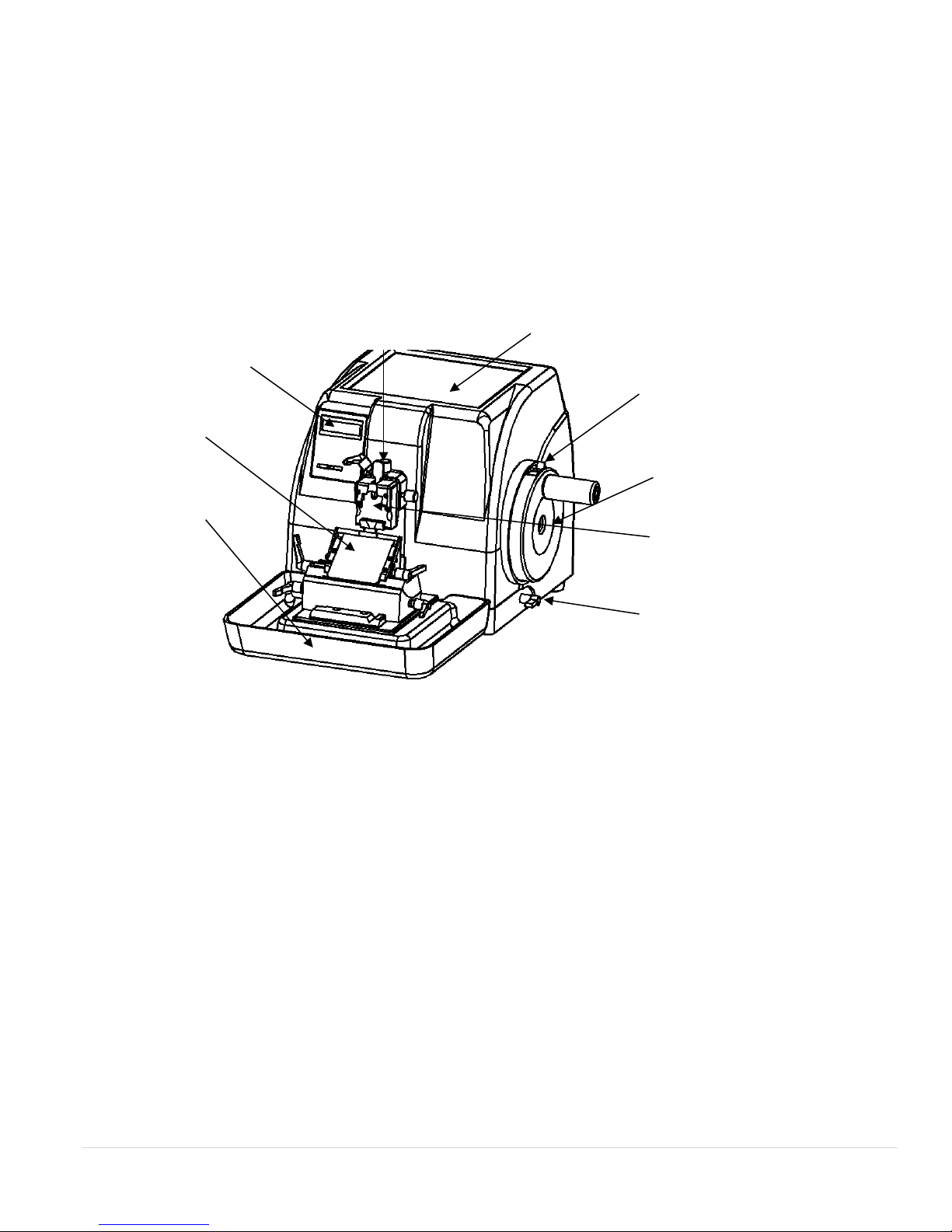
Operator Controls and Components
Operator’s hand wheel
Hand wheel locking mechanism
Lever for 360° hand wheel
brake
Section waste tray
Blade holder
Display panel
Storage Tray
Quick-Release cassette clamp
Clamp Adjuster

5 | Page
General Data Healthcare, Inc.
Table of Contents
Operator Controls and Components....................................................................................................... 4
Declaration of Conformity....................................................................................................................... 6
Instrument Compliance............................................................................................................................ 7
Section1 | Safety Instruction .................................................................................................................... 8
Summary.........................................................................................................................................................................8
Safety Notes....................................................................................................................................................................8
Safety Devices................................................................................................................................................................9
Section 2 | Specifications......................................................................................................................... 10
Technical Data..............................................................................................................................................................10
Section 3 | Preparation.............................................................................................................................11
Installation Site Requirements......................................................................................................................................11
Standard Accessory List.............................................................................................................................................11
Installation....................................................................................................................................................................12
Blade Holder.............................................................................................................................................................12
Waste Tray................................................................................................................................................................12
Electrical Connection ...................................................................................................................................................13
Section 4 | Operation............................................................................................................................... 14
Control Panel and Its Features......................................................................................................................................14
Display Panel............................................................................................................................................................14
Blade Holder.................................................................................................................................................................16
Specimen Clamping System.........................................................................................................................................17
Clamping the Specimen and Blade Installation............................................................................................................18
Activating Trimming ....................................................................................................................................................19
Activate Sectioning.....................................................................................................................................................19
Section 5 | Cleaning and Maintenance.................................................................................................. 21
Cleaning the Clamp......................................................................................................................................................21
Cleaning the Blade Holder: ..........................................................................................................................................22
Section 6 | Troubleshooting .................................................................................................................... 23

6 | Page
General Data Healthcare, Inc.
Konformitätserklärung
Déclaration de conformité
Declaración de Confomidad
Verklaring de overeenstemming
Dichiarazione di conformità
We/Wir/ Nous/WIJ/Noi
TBS-A Division of General Data Healthcare.
Declare under our sole responsibility that the product,
erklären, in alleniniger Verantwortung,daß dieses Produkt,
déclarons sous notre seule responsabilité que le produit,
declaramos, bajo nuestra sola responsabilidad, que el producto,
verklaren onder onze verantwoordelijkheid, dat het product,
dichiariamo sotto nostra unica responsabilità, che il prodotto,
SHURCut™ 2500 Semi-Automated Rotary Microtome
to which this declaration relates is in conformity with the following standard(s) or other normative documents.
auf das sich diese Erklärung bezieht, mit der/den folgenden Norm(en) oder Richtlinie(n) übereinstimmt.
auquel se réfère cette déclaration est conforme à la (aux) norme(s) ou au(x) document(s) normatif(s).
al que se refiere esta declaración es conforme a la(s) norma(s) u otro(s) documento(s) normativo(s).
waarnaar deze verklaring verwijst, aan de volende norm(en) of richtlijn(en) beantwoordt.
a cui si riferisce questa dichiarazione è conforme alla/e seguente/i norma/o documento/i normativo/i
Declaration of Conformity

7 | Page
General Data Healthcare, Inc.
Instrument Compliance
TBS-A Division of General Data Healthcare hereby declares the equipment specified conforms to the Classification(s),
Directive(s) and Standard(s) set forth in this document.
Certifications: CE, TUV
EMC Emissions
FCC 47 CFR Part 2, Part 15 CISPR PUB.22 (USA)
EMC Immunity:
EN 55011:2007: (Class B), EN 61000-3-2:2006/A2:2009, EN 61000-3-3:2008, EN 61326-1:2006
IEC 61000-4-2:2008, IEC 61000-4-3:2010, IEC 61000-4-4:2010, IEC 61000-4-5:2005, IEC 61000-4-6:2008
IEC 61000-4-8:2009, IEC 61000-4-11:2004
EN 61010-1: (Third Edition) :2001, EN61010-1:2010

8 | Page
General Data Healthcare, Inc.
Section1 | Safety Instruction
Summary
This instrument was built and tested in accordance with the safety regulations as specified below:
Gb9706.1-1995 medical electricity equipment
Note
:
Safety instruction labels on the instrument must be kept in the original place to
avoid an accident, personal injury, or damage to the instrument.
Safety Notes
The following instructions are regarding the transport, installation, regulation, operation
and maintenance of the instrument which must be read and complied with.
Warnings-Transport and Installation
The instrument may only be transported in an upright position.
Never lift the instrument by the hand wheel or the cassette clamp. Always
remove the section waste tray and blade holder before transporting the
instrument.
Check to make sure that the voltage available at your facility complies with the
requirements of this unit.
Connect the unit using the power cable provided. It is critical to connect to a
grounded socket.
Do not operate in rooms with explosion hazards.
Do not tamper with the safety devices of the unit.
Warnings-Working with the Instrument
Take great care in handling microtome blades. The cutting edge is extremely
sharp and can cause serious injury.
Always remove the blade and put in a safe location before detaching the blade
holder from the unit.
Always clamp the specimen block before inserting or clamping the blade.
Always keep the hand wheel locked when handling the blade or specimen on
the unit. Cover the cutting edge with the blade guard.

9 | Page
General Data Healthcare, Inc.
Place the blade guard over the blade when sectioning.
Make sure that liquids do not enter the interior of the instrument.
1.2.3 Warnings-Cleaning and Maintenance
Only authorized and qualified service personnel may access the internal
components of the instrument for service and repair.
Before each cleaning, switch the unit off, disconnect the power plug, and
remove the blade holder completely and clean it separately.
Lock the hand wheel before each cleaning.
Do not use any solvents containing acetone or xylene for cleaning.
Make sure that liquids do not enter the interior of the instrument when
cleaning.
Let the unit dry completely before powering up again.
Turn the unit off and disconnect the power plug before replacing fuses. Only
use fuses of the same specification and replace them as described in the
manual.
Safety Devices
Handwheel Locking Mechanism
There are two handwheel locking mechanisms.
•Locking mechanism indicated by (1) on the
diagram can be engaged by flipping the
corresponding switch and rotating the hand
wheel to the upper most position where it will
lock into position.
•Locking mechanism indicated by (2) on the
diagram can be engaged in any position of the
handwheel by rotating the handle 180°
clockwise. To unlock, rotate 180° counter
clockwise.
Do not lock the handwheel (1) when the handwheel is rotating as it will
damage the unit.
Whenever cleaning the unit, changing the specimen, or changing the blade,
make sure the handwheel is locked with either mechanism (1) or (2).
1
2
10 | Page
General Data Healthcare, Inc.
Blade guard
•Position the blade guard (3) over the blade
when not operating the unit to avoid personal
injury and prevent damaging the blade edge.
•The blade guard(3)in Fig is shown in the up
position where it protects the blade.
Section 2 | Specifications
Technical Data
SC2500
Item:
Description:
Dimensions
Length: 21.6 in (55 cm)
Width: 16.5 in (42 cm)
Height: 12.6 in (32 cm)
Weight:
92 lbs. (42 kg)
Environment requirements:
Working temperature
:
+10
℃
—40
℃
Working humidity: <80%
Working pressure:
(
86
~
106
)
kpa
Power Supply:
110/220 v ac±10 %
Frequency:
50/60 Hz
Fuse:
1.5 Amps
Safety Classification:
I - Type b
Blade Profile
Low Profile Blade – Recommended, DMB-LP SHUR/Sharp™
Disposable Microtome Blade, Low Profile, Teflon Coated; (0.012”
x 0.312” x 3”
Trimming/Section
Thickness:
0.5 to 600µm
0.5 to 2µm - 0.5µm increments
2 to 10µm - 1µm increment
10 to 20µm - 2µm increments
20 to 100µm - 5µm increments
100 to 600µm - 50µm increments
3

11 | Page
General Data Healthcare, Inc.
SC2500 (cont.)
Item
Description
Retraction thickness:
20µm
Specimen horizontal feed:
20mm
Specimen vertical feed:
70mm
Maximum specimen size:
40mm x 50mm x 30mm or standard cassette size
Specimen holder
adjustment system:
Horizontal orientation: ±8°
Vertical orientation
:
±8°
Left/Right Blade holder
adjustment:
50mm
Section 3 | Preparation
Installation Site Requirements
Place the unit on a well-supported table. Ensure the table is sitting level.
Ensure that the operating temperature and humidity is according to spec.
Ensure that there is nothing obstructing the handwheel operation.
Standard Accessory List
Part:
Quantity:
Microtome
1
Blade holder
1
Quick Release Clamp for Standard Cassette
1
Waste Tray
1
M3 Wrench
1
M4 Wrench
1
Disposable Blades
1
Fuse
2
Operation Manual
1

12 | Page
General Data Healthcare, Inc.
1
2
3
Installation
Blade Holder
Remove the blade holder (1) from the box, and
push it along the track as it is showed in the
picture, and then rotate the blade holder locking
lever (2) to lock the blade holder.
Waste Tray
Remove the waste tray (3) out from the box and
push it along the track as it is showed in the picture.

13 | Page
General Data Healthcare, Inc.
4
5
6
Electrical Connection
Check to make sure that the voltage available at your facility complies with the
requirements of this unit.
Connect the unit using the power cable provided. It is critical to connect to a
grounded socket.
Before changing a fuse, make sure to disconnect power from the unit.
1. Insert the fuse (6) into the fuse socket (5) as it is
showed in the picture and the insert the whole fuse
socket into the socket (4).
2. Energize the equipment with the switch at
the rear right side. The instrument should
initialize.
3. After the microtome is energized, the display
field in the control panel will illuminate. The
specimen holder will automatically retract
back to zero. This is followed by a beep.
14 | Page
General Data Healthcare, Inc.
Section 4 | Operation
Control Panel and Its Features
All the parameters are set and displayed via the control panel. After being energized, use the control
panel to operate the instrument, the following is a diagram explaining the functions of the control
panel.
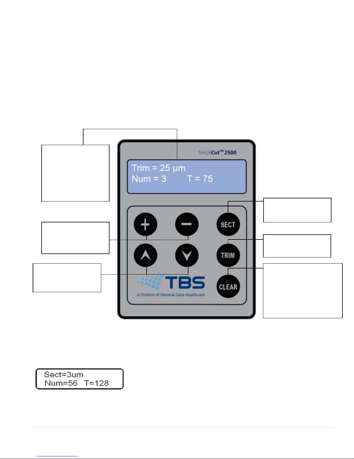
Display Panel
•The value in the first line of the display window is the set
sectioning or trimming thickness.
The value in the second line of the display window is the
section or trim counter and section or trim thickness sum (total
advance).
•The system is in trimming mode after energize the
instrument.
LCD display: section
thickness / trimming
thickness; section
counter & total
sectioned amount
Buttons for setting
section thickness and
trimming thickness
Coarse feed
Backwards / Forwards
The button activates
the sectioning mode
The button activates
the trimming mode
Button to clear the display
parameters to 0:
1. section counter
2. section thickness sum
15 | Page
General Data Healthcare, Inc.
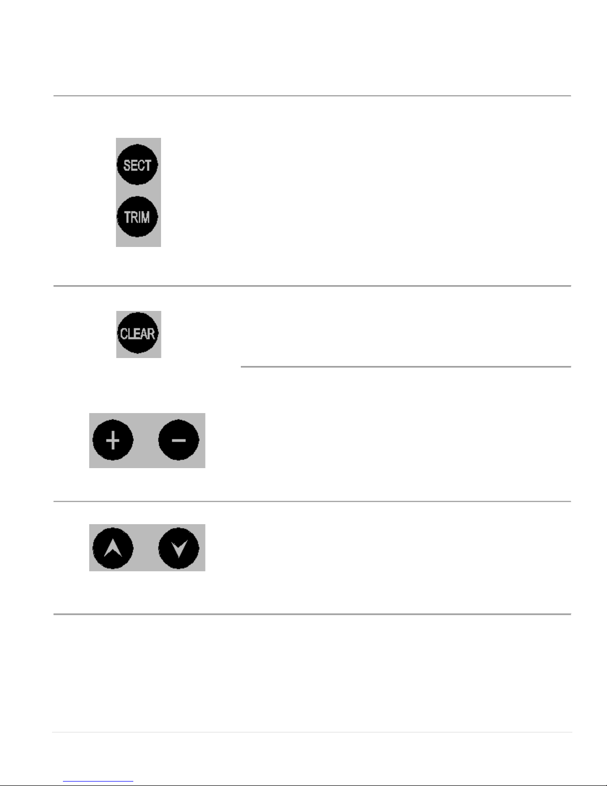
SECT Button
•SECT button activates the sectioning mode. The first line on the
display will show [SECT=]. Used to adjust section thickness
TRIM Button
•TRIM button activates the trimming mode. The first line on the
display will show TRIM=. Used for setting the TRIM thickness
•When the unit is powered on, it will display the last set value for
the section or trimming mode.
•Pressing the CLEAR button will clear the section / trimming counter
and the thickness sum (total advance).When the instrument is
energized, the value of the section counter and section thickness sum
will automatically go back to zero.|
•Press the + (plus) button or – (minus) button to set the section or trim
value.
Adjusting range: 0.5 to 600µm
0.5 to 2µm,0.5µm increments
2 to 10µm,1µm increment
10 to 20µm,2µm increments
20 to 100µm,5µm increments
100 to 600µm,50µm increments
•The arrow buttons control the forward and backward direction of the
arm that holds the specimen. The advance and retract speed is
750µm/s.
•The max forward and backward distance is 20mm. If the maximum
distance is exceeded, the specimen holder will stop moving and an
alarm will sound.

16 | Page
General Data Healthcare, Inc.
Blade Holder
•The blade holder consists of the blade holder base
(2), X-axis slider (3), and the blade holder clamp
(4).
•The whole assembly sits on the base plate (1)
attached to the microtome.
•The X-axis slider (3) allows for 10 degrees of
adjustment of the blade with respect to the specimen.
•The pictures below explains which component each
lever locks.
Always remove the blade first before detaching any of the components of the blade
holder assembly.
Always make sure that all 4 levers on the blade holder are tight before using the
microtome to avoid potentially ruining a specimen sample.
The lever on the left operates
the blade holder clamp.
The lever on the right
operates the X axis slider
clamp.
The lever on the left operates
the Y axis slider clamp.
4
2
1
3

17 | Page
General Data Healthcare, Inc.
Specimen Clamping System
•To actuate the specimen holding arm (1), rotate the
handwheel (2) clockwise.
•The specimen clamping system comes with two separate
clamps:
oQuick Release Clamp (5):
Dimension of Specimen:
40mm x 50mm x 30mm or the standard
cassette size.
oC-Type Clamp (6) (Optional Accessory):
Dimension of Specimen:
Accepts standard cassette size as well as any
specimen carrier that is less than 40mm in
length/width. The clamp will also accept
carriers as small as 12mm in length/width.
•The clamps (5 or 6) attach to a connector (4) which
attaches itself to the adjuster (3).
•To attach a clamp, first attach the connector (4) to the
adjuster (3) using four screws. Then attach either the
Quick Release Clamp using two screws or the C-Type
Clamp using four screws.
•The specimen clamp adjustor allows for the specimen to
be swiveled in the horizontal and vertical direction:
oHorizontal orientation: ± 8°
oVertical orientation:±8°
•To make an adjustment, first loosen the lever (7). Next,
you are able to either adjust the vertical orientation using
the knob on top (8) or the horizontal orientation using the
knob of the right side (9). After the adjustments are made,
retighten the lever(7).
1
2
6
4
5
3
8
7
9

18 | Page
General Data Healthcare, Inc.
Clamping the Specimen and Blade Installation
Clamping the specimen:
•Using the C-Type Specimen Clamp:
oPut the specimen (4) into the clamp (1) as is
shown in the picture. Then rotate the nut (3)
clockwise to tighten the clamp. To remove
the specimen, rotate the nut
counterclockwise.
•Using the Quick Release Clamp:
oPull the clamp handle (5) in the direction
showed in the picture. The clamp will open.
You can now insert the specimen (6) into the
clamp (2). Release the handle (5), the
specimen will be clamped automatically. To
remove the specimen, repeat the same
operation.
Always clamp the specimen
first before installing the blade
to avoid injury.
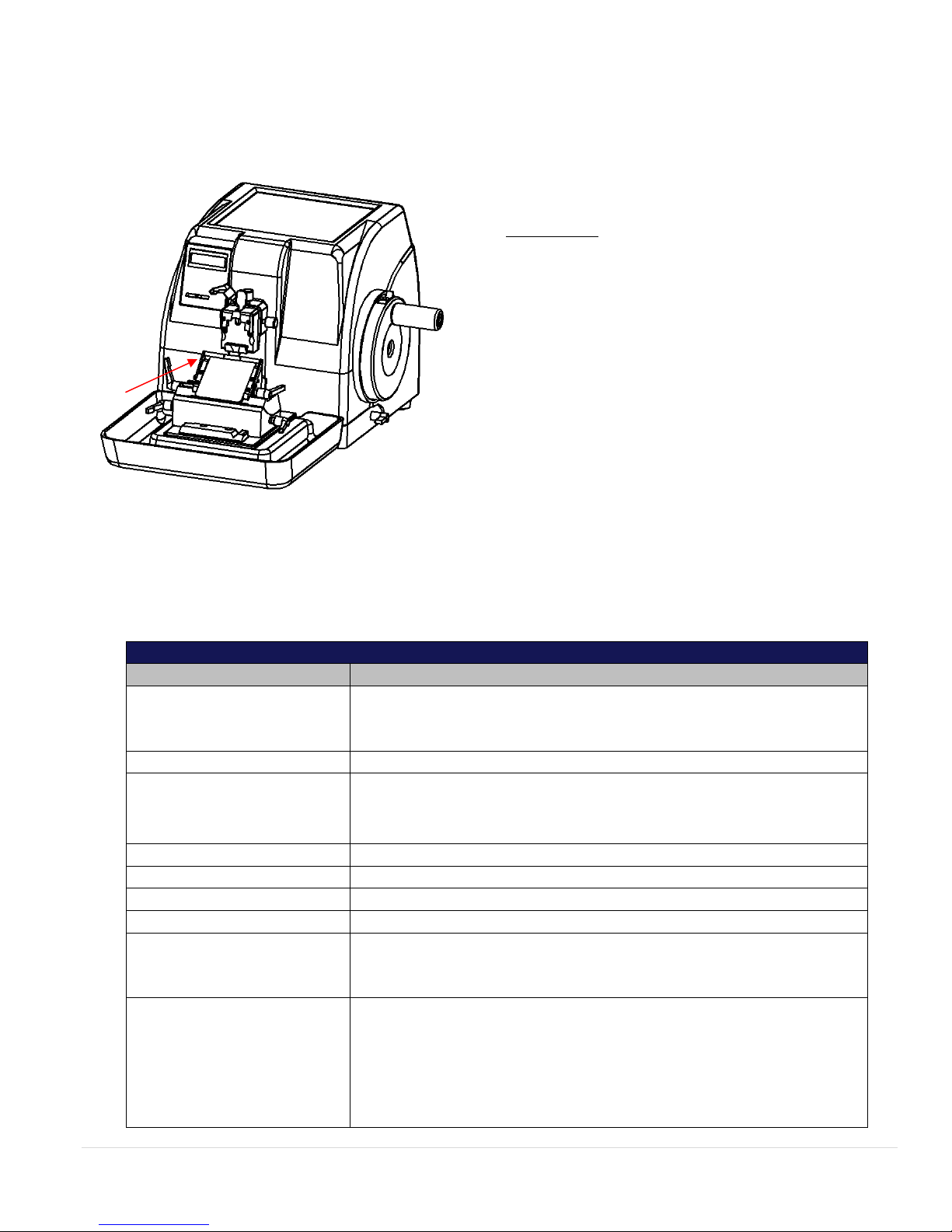
Installing the blade:
•Before installing the blade in the blade holder
clamp, make sure that the blade holder base is
secured (9). Then, choose the angle of the X-Axis
slider and secure it using lever (10). Choose the
lateral location of the blade holder clamp and
secure it using lever (8). Finally, place the blade
in the blade holder clamp as shown by the red
arrow (11) and secure it using lever (7).
1
3
4
2
6
5
8
10
9
7
11

19 | Page
General Data Healthcare, Inc.
Activating Trimming
•To activate the trimming mode, press the button. The screen
will display the set parameters of trimming.
•To set the trim thickness, press the button. The screen will
display the trim thickness value.
•Press the directional buttons to adjust the specimen
forward and back to ensure the specimen is lined up with the
cutting edge.
•Finally, make sure the levers that secure the blade holder are all
tightened. The unit is now ready to section. Unlock the handwheel
and begin to rotate it clockwise to section.
Activate Sectioning
•To activate the SECT mode, press the button and the
instrument goes into sectioning mode, and the screen will display
the set parameters of sectioning.
•Press the buttons to set the sectioning thickness value.

20 | Page
General Data Healthcare, Inc.
•To obtain optimum quality sections, the following factors need to be taken into consideration:
a. The hardness of the specimen
b. The angle of the cutting blade
c. The blade is clamped tightly
d. The specimen is clamped tightly.
•To obtain a quality section, first adjust the proper angle of the cutting blade and the specimen:
a. The smaller the angle, the less the section will be compressed.
b. The harder the specimen, the larger the angle will be needed.
c. If the section is not good, try increasing the angle from zero.
When finished sectioning, turn the handwheel until the specimen is in the upper most
position, lock the handwheel, remove and safely dispose of the blade.
This manual suits for next models
1
Table of contents
Other tbs electronics Laboratory Equipment manuals


