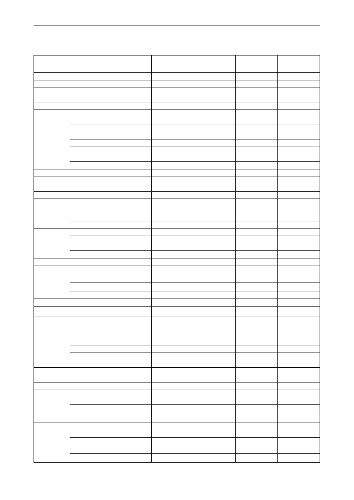
TCL TAC-07CHSA/XA71 User manual

TCL
WALL MOUNTED SPLIT-TYPE AIR CONDITIONERS
SERVICE MANUAL No.190220
Models
TAC-07CHSA/XA71TAC-09CHSA/XA71
TAC-12CHSA/XA71TAC-18CHSA/XA71
TAC-24CHSA/XA71
CONTENTS
1. IMPORTANT NOTICE
2. TECHNICAL SPECIFICATION
3. PRODUCT DIMENSIONS
4. REFRIGERATION CYCLE DIAGRAM
5.OPERATION DETAILS
6. WIRING DIAGRAM
7. EXPLOSION VIEW AND PART LISTS
8. PRECAUTION
9. NAMES OF PARTS
10. INSTALLATION
11. TROUBLE SHOOTING

Air Conditioner Service Manual
1
1. IMPORTANT NOTICE
This service manual is intended for use by individuals possessing adequate
backgrounds of electrical, electronic and mechanical experience. Any
attempt to repair the appliance may result in personal injury and property
damage. The manufacturer or seller cannot be responsible for the
interpretation of this information, nor can it assume any liability in
connection with its use.
The information, specifications and parameters are subject to change due
to
technical modification or improvement without any prior notice. The
accurate specifications are presented on the nameplate label.
How to order spare parts
To have your order filled promptly and correctly, please furnish the
following information:
6
Model No. with Indoor or Outdoor
7
Part No. in the Explosion View
8
Part Name
9
The quantity you ordered

Air Conditioner Service Manual
2
2. TECHNICAL SPECIFICATION
Model No.
TAC-07CHSA/XA71 TAC-09CHSA/XA71 TAC-12CHSA/XA71 TAC-18CHSA/XA71 TAC-24CHSA/XA71
Type
heating pump
heating pump
heating pump
heating pump
heating pump
Control type
remote
remote
remote
remote
remote
Rated cooling capacity
Btu/h;W
7000;2050
9000;2640
12000;3520
18000;5280
24000;7030
Rated heating capacity
Btu/h;W
7500;2200
9500;2800
12500;3700
18500;5420
24500;7200
EER for cooling
W/W
10.95; 3.21
10.98; 3.22
10.95; 3.21
11.02; 3.23
10.98; 3.22
COP for heating
W/W
3.61
3.62
3.62
3.61
3.63
Moisture removal
Liters/h
0.8
1.0
1.2
2.0
2.2
Pressure
High(DP)
MPa
4.5
4.5
4.5
4.5
4.5
Low(SP)
MPa
1.9
1.9
1.9
1.9
1.9
Indoor noise level
at cooling
SUPER
dB(A)
34
35
42
43
43
High
dB(A)
32
33
40
40
43
Med
dB(A)
29
29
37
38
38
Low
dB(A)
27
27
34
37
37
MUTE
dB(A)
26
25
31
37
37
Outdoor noise level
dB(A)
48
48
49
55
55
Electrical Data
Power supply
220-240V/50Hz
220-240V/50Hz
220-240V/50Hz
220-240V/50Hz
220-240V/50Hz
Voltage Range
V
220
220
220
220
220
Rated current
Cooling
A
3.0
3.8
5.1
7.6
10.1
Heating
A
2.8
3.6
4.7
7.0
9.2
Rated input
Cooling
W
640
820
1100
1640
2180
Heating
W
610
775
1020
1500
1985
Max Current
Cooling
A
3.9
4.9
6.6
9.9
13.1
Heating
A
3.6
4.7
6.1
9.1
12.0
Max Power input
Cooling
W
830
1060
1430
2130
2830
Heating
W
800
1010
1325
1950
2580
Refrigerating System
Refrigerant/Charge
Gram
R410A/430g
R410A/510g
R410A/640g
R410A/930g
R410A/1300g
Compressor
Model
ASN89V11UDZ1
ASN89V11UDZ1
PA140G1C-4DZ1
50A403VL-51KG
ASH232MV-C7EU1
MFG
GMCC
GMCC
GMCC
RECHI
HIGHLY
Type
Rotary
Rotary
Rotary
Rotary
Rotary
Fan System
Indoor air
circulation(Cooling/Heating)
m3/h
350/350
380/380
560/580
800/800
850/850
Indoor fan type
Cross flow
Cross flow
Cross flow
Cross flow
Cross flow
Indoor fan speed
H/M/L
Cooling
rpm
1270/1150/1050
/900/800
1270/1150/1050
/900/800
1400/1260/1100
/900/850
1250\1150\1000
\900\800
1300/1200/1100
/1050/1000
Heating
rpm
1270/1150/1050
/900/800
1270/1150/1050/900
/800
1400/1260/1100/950
/900
1250\1150\1050\950
\900
1300/1200/1100/105
0/1000
Dry
rpm
900
900
900
900
1050
Sleep
rpm
900
900
900
900
1050
Indoor fan motor output
W
13
13
20
18
25
Outdoor fan type
Propeller
Propeller
Propeller
Propeller
Propeller
Outdoor fan speed
rpm
850
850
860
850
840
Outdoor fan motor output
W
20
20
31
45
68
Connections
Connecting Pipe
Gas
Inches
Φ9.52(3/8'')
Φ9.52(3/8'')
Φ9.52(3/8'')
Φ12(1/2'')
Φ15.88(5/8'')
Liquid
Inches
Φ6(1/4'')
Φ6(1/4'')
Φ6(1/4'')
Φ6(1/4'')
Φ6(1/4'')
Connecting
Wiring
Size x Core number
3×1.0;2×0.75
3×1.0;2×0.75
3×1.0;2×0.75
3×1.5;2×0.75
3×1.5;2×0.75
Drainage Pipe
O.D 16mm
O.D 16mm
O.D 16mm
O.D 16mm
O.D 16mm
Net dimensions
(W x H x D)
Indoor
mm
698×255×190
698×255×190
777×250×201
910×294×206
910×294×206
Outdoor
mm
654×276×507
654×276×507
777×290×498
817×328×553
886×357×605
Packing
dimensions
(W x H x D)
Indoor
mm
764×325×257
764×325×257
840×315×260
979×372×277
979×372×277
Outdoor
mm
700×300×545
700×300×545
818×325×520
858×321×585
930×380×635

Air Conditioner Service Manual
3
3. Product Dimensions
Indoor Unit:
Outdoor Unit:
Model
Indoor unit
Outdoor unit
A
B
C
D
E
F
G
H
I
J
K
TAC-07CHSA/XA31
698
255
190
600
500
232
357
276
256
52
55
TAC-09CHSA/XA31
698
255
190
600
500
232
357
276
256
52
55
TAC-12CHSA/XA31
777
250
205
700
550
256
439.2
302
277.8
48
55
TAC-18CHSA/XA31
910
292
205
760
550
256
508
302
277.8
48
55
TAC-24CHSA/XA31
910
292
205
820
605
300
518
357
329
55
63

Air Conditioner Service Manual
ϰ
4. Refrigeration cycle diagram
Cooling only
Heat pump
Capillary
Compressor
Accumulator
Heat exchange
(condenser)
Heat exchange
(Evaporator)
2-way valve
Liquid side
3-way valve
Gas side
Cooling
Heating
Gas side
3-way valve
Liquid side
2-way valve
Heat exchange
(Evaporator)
Heat exchange
(condenser)
Accumulator
Compressor
4-way valve
Capillary Assembly
Check valve

5
Note: Each mode and relevant function will be further specified in following pages.
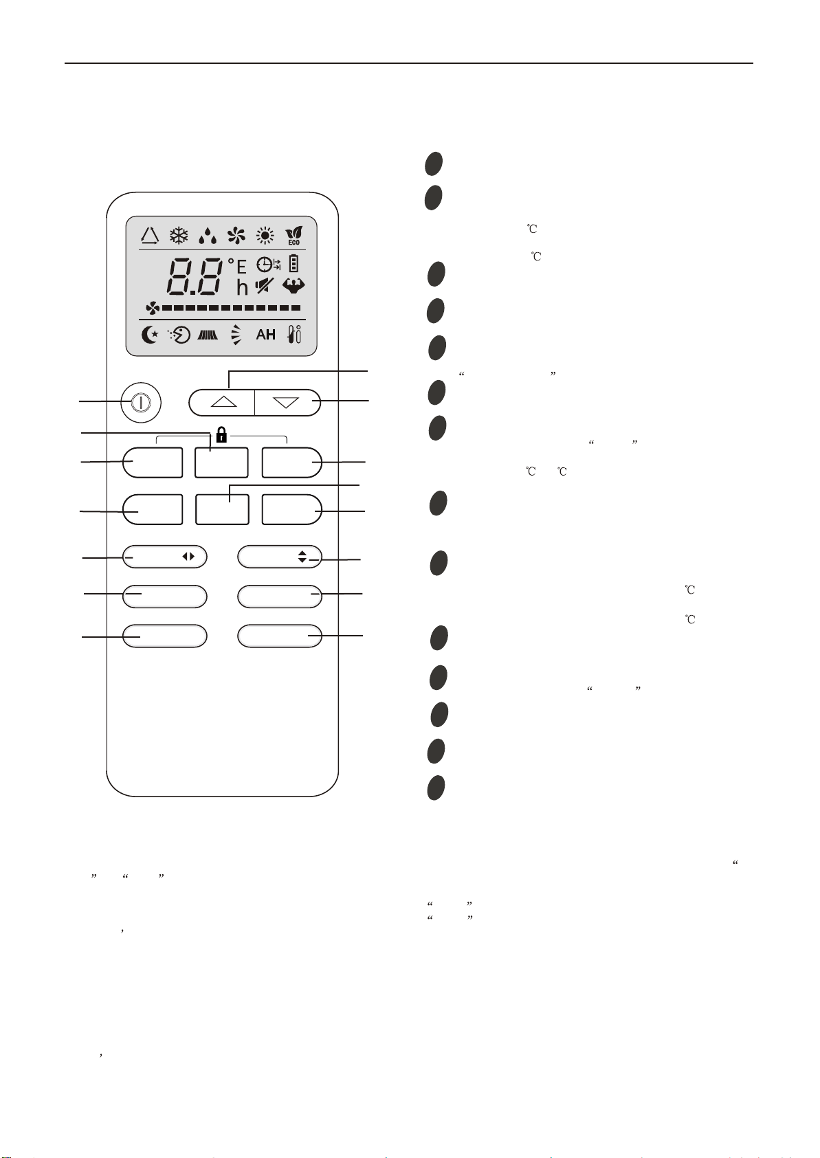
Remote controller
1
2
4
3
5
6
9
7
MODE button
ECO button
FAN SPEED button
TEMP UP button
TIMER button
SLEEP button
TEMP DOWN button
To select the mode of operation.
In cooling mode,press this button ,the temperature
will increase 2 on the base of setting temperature:
In heating mode, press this button, the temperature
will decrease 2 on the base of setting temperature.
To switch the conditioner on and off.
To select the fan speed of auto/low/mid/high.
To set automatic switching-on/off.
Increase the temperature or time by 1 unit.
To activate the function SLEEP .
Decrease the temperature or time by 1 unit.
Air Conditioner Service Manual
5.Operation Details
Remote Control
The remote controlleris not presetting as CoolingOnly AirConditioner or HeatPump by manufacturer.
Each time after the remotecontroller replace batteriesor is energized,the arrowhead willflashes on thefront of
Heat or Cool on LCD of the remote controller.
User can presetthe remote controllertype depending onthe air conditionertype you havepurchased as follows:
Press any buttonwhen the arrowheadflashes on thefront of Cool , Cooling Onlyis set.
Press any buttonwhen the arrowheadflashes on thefront of Heat , Heat Pumpis set.
If you don t press any button within 10 seconds, theremote controller ispreset as HeatPump automatically.
LOCK/UNLOCK
Note :
If the air conditioner you purchased is a Cooling Only one, but you preset the remote controller as Heat Pump, it
doesn t bring anymatter. Butif the airconditioner you purchasedis a HeatPump one, and you preset the remote
controller as CoolingOnly, then you CAN NOT preset the Heating operation with the remotecontroller.
When you pressthe buttons "MODE"and "TIMER" atthe same time,the remote controllerwill be locked, all buttons
of the remotecontroller will bedeactive and itdisplays "Lo" .You can operateagain as thesame way tounlock the
remote controller.
8
DISPLAY button
In cooling mode, press this button, the unit will give
the maximum cooling temperature with 16
In heating mode, press this button, the unit will give
the maximum heating temperature with 31 .
9
SWING button
10
To activate or deactivate of the movement of the
DEFLECTORS .
12
HEALTH button
9
3
4
2
1
8
5
6
7
5
9
10
11
9
ON/OFF button
11
To LED display (if present)switch on/off the
12
TURBO button
MODE
FAN SLEEP
ECO TIMER
SWING
TURBOMUTE
DISPLAY
SWING
HEALTHI FEEL
13
14
13
14
I FEEL button
To switch - activr/deactive I FEEL function. The air
conditioner will regulate the room temperature base on the
temperature(0 ~50 ) around the remote controller.This
function will terminate 2 hours later once it's active.
To switch - on /off HEALTHY funtion.
It is a button
which controls the ionizer or plasma generator only
for inverter type.
MUTE button
To activate the function of Mute.

Air Conditioner Service Manual
6
Electronic controller
NOTES:
RT-------Room Temperature.
IPT------Indoor Pipe Temperature.
ST------indoor Setting Temperature.
OPT---Outdoor Pipe Temperature.
CRT---Compensated Room Temperature
1. Automatic mode
1) The initial RT determines A/C working mode and the setting temperature (ST), the mode is
determined effective only once unless A/C shut-down and then re-started. If from other mode
switches to automatic mode (including mode conversion after shutdown), it should be that the
compress stop more than 3 min then temperature judgment and automatic mode are conducted (it
can conduct immediately from fan mode switched to automatic, the indoor fan stops, three minutes
later the response is made and start up). Within 3 min, the output as: Showing the room
temperature, indoor fans starts (or anti-cold airflow), the outdoor fan stops;
Withautore‐startcontroller,oncebeingturnedofforincaseofanaccidentlypowercut,theA/Cisableto
retainandrestoretheoriginalmodewhenbeingturnedonorthepowersupplyisresumed,iftheauto
restartfunctionactivated.power‐offafterpower‐on;whileiftheautorestartfunctionisn’tactivated,
theA/Centersstandbystate.
Heat pump
Mode Initial RT Initial ST
Cooling RT≥26°C 23°C
Dry 26°C>RT≥20°C 7°C
Heating RT<20°C 23°C
Cooling-only
Mode Initial RT Initial ST
Cooling RT≥26°C 23°C
Dry 26°C>RT≥20°C 7°C
Ventilating RT<20°C -
Under automatic mode (including from automatic converted into Dry mode), when A/C received the
temperature UP or DOWN signals from the remote controller, the setting temperature (ST)
adjusts
correspondingly to the current room temperature plus or minus 1°C, the automatic regulating
temperature range is ± 2°C.
2. Cooling mode
1) The control of the compressor
a.
When RT-ST≥1°C,the compressor is running.
b.
When RT-ST<-1°C,the compressor stops.
c.
When-1°C≤RT-ST<1°C, the compressor keeps its original state.
2) Outdoor fan motor and the compressor run simultaneously (except for defrosting).
3) The control of indoor fan motor:
a.
Indoor fan motor can operate by automatic, low, middle, or high airflow speed circularly.

Air Conditioner Service Manual
7
b.
Indoor fan motor automatic airflow speed control, it works as shown in Figure 1:
Hi
Mid
Lo
RT-ST 1°C 2°C 4°C
Figure 1 Cooling automatic airflow
When the temperature changing leads the fan speed variation, the switch can only be made orderly,
and in every grade of air flow speed should run 1 minute at least.
3. Dry mode
While select to this mode, the air conditioner operates for 3 minutes according to cooling mode firstly
(ST set at 7°C), and then takes the detected backflow air temperature minus 2°C as a new set
temperature (the lowest temperature: 5°C) and runs according to cooling mode, indoor fan operates at
low-speed, at this moment the setting operation of fan speed invalid but Swing adjustable.
4. Heating mode
On the Heating mode, the room temperature (RT) is compensated (CRT), a fter that, the room
temperature displayed on the LED is CRT=RT-3°C.
1) The control of the compressor
a.
When ST-CRT≥1°C,the compressor is running.
b.
When ST-CRT<-1°C,the compressor stops.
c.
When -1°C≤ST-CRT<1°C, the compressor keeps its original state
2) Outdoor fan motor and the compressor run simultaneously (except for defrosting)
3) The control of indoor fan motor:
a.
Indoor fan motor can operate by automatic, low, middle, or high airflow speed circularly.
b.
Indoor fan motor automatic airflow speed control, it works as shown in Figure 2:
Figure 2 Heat automatic airflow
When the temperature changing leads the fan speed variation, the switch can only be made orderly,
and every grade of air flow speed should run 1 minute at least.
4) Vane motor control: run as set state.
5) 4-way valve control:
a.
Under heating mode, the four-way valve maintains well-connected status (including the
compressor stops on set condition, except for the defrosting process)
b.
When the mode switches into the heating mode or A/C start-up, four-way valves will open 5
Seconds before the compressor starts; while the mode exits from the heating mode or A/C turn off,
the four-way valve will close 2min later after shut-down the compressor.
Hi
Mid
Lo
ST-CRT 1°C 2°C 4°C

6) Defro
During de
buzzer an
defrosting
During de
Fan spee
Except th
buzz for r
During de
Defrosting
Option 1
The cond
Condition
Definition
The follow
a.
IPT1 s
b.
t5≥50m
be less th
c.
IPT<4
Running i
defrosting
Condition
accumula
under con
Condition
less than
temperatu
and the m
osting functio
efrosting, on
nd display w
gfinished;
efrosting, the
ed and/or Sw
he above sig
response.
efrosting, ele
gEnter and
:with jump
dition ofente
n1:As show
n:
wing conditio
settles for IP
min(running
han t1)
40°C,and l
into defrostin
gcycle, the d
n2: When ru
atively), the i
ndition 2, de
n3: After the
n23°C (cold
ure dropping
machine run
on:
ce mode ch
will make res
esignals of O
wing should b
nal process
ectrical heati
Exit program
per JC
er defrosting:
wn in figure
ons a, b and
PT1=IPTma
gtime t5≥50
lasts 2min。
ng on condit
defrosting tim
unning time i
indoortemp
efrosting time
ecompresso
air preventi
gwhen com
s into defros
Air C
anging, eco
sponse imme
On-Off, Tim
be in accord
ing during d
ing (optiona
m:
:run into de
3
dc all require
ax-ᇞIPT
0min(the co
tion 1, the fir
me should b
is more than
erature is le
eset is 8 mi
or is operatin
on wind tem
mpressorope
sting accordi
Conditioner Se
nomic opera
ediately, but
ing, Sleep, F
dance with o
efrosting, no
l function) st
frosting onc
ed to meet:
ompressor ru
rst running ti
be determine
Figure 3
nor equal to
ss than 35°C
n.
ng for20min
mperature) w
erating, not i
ing to any on
rvice Manual
ation ortemp
tthe other o
Fan speed a
operation for
oother signa
tops compu
e any of con
uns cumulati
me of set de
ed and adjus
3
120 min (co
Cfor 2 min s
continuous
when the fan
ncluding the
ne condition
perature set
perations wo
and/or Swing
rCold Air Pr
als will deal
lsively.
ndition 1, 2,
vely),t5 is re
efrosting is F
sted.
ompressoris
sustained. R
ly, the indoo
stops runni
ecompresso
as below.
tting signals
on’t impleme
gcan respon
revention.
with, only a
and/or 3 me
emovable,a
F(8min); afte
srunning
Running into
or pipe temp
ng (including
or’s starting
received, th
ent until
nd, but the
voice of
et.
and could
er running a
defrosting
erature is
g
up course),
8
he
a

Air Conditioner Service Manual
9
Running into defrosting under condition 3, defrosting time set is 10 min.
a) Running into the first defrosting in 20 min after start-up.
b) The interval from last defrosting equivalent to or more than 50 min (stopping the compressor or the
machine in standby is allowed in the meantime).
Option 2: Without Jumper JC, and no OPT outdoor sensor
when the compressor runs for 45 min (accumulated), if the indoor coil temperature is less than 40°C for
2 min, the machine runs into defrosting, and lasts for 3min, otherwise when the compressor
runs for 120 min (accumulated), the machine runs into defrosting automatically and last for 10 min.
Option 3: Without jumper JC, but with OPT outdoor sensor
While heating, when the temperature of condenser is lower than E °C (-4°C), and the compressor runs
for 45 min (accumulated), then the machine runs into defrosting and lasts for 10 min.
Option 4. On heating, while the outdoor fan motor stopped but the compressor operated
accumulative totally 30min, then the machine runs into defrosting and last for 8 min. if the accumulative
totally less than 30min, but accord with one of the condition option 1-3 then the machine runs into
defrosting at the option 1-3 and the accumulative total time restarts from 0.
Conditions for quitting defrosting
(1) The quitting conditions for option 1, option 2 and 4, the machine quits from defrosting if any one
below condition met.
6
a. Defrosting time is over.
7
b. When it runs in defrosting for three minutes, the IPT indoor coil temperature rises 15°C or above
from the bottom point.
(2) The quitting conditions for option 3.
When OPT ≥20°C or defrosting for more than 10 min, then quit from defrosting.
(3) Defrosting process shown in Figure 4
Figure 4 Defrosting process
7) Auxiliary electric heating function (optional)
(1) The default condition is automatic on/off the electric heating function.
(2) The conditions of auxiliary electric heating works (all the following conditions must be met)
a.
the compressor runs for more than 3min;
b.
indoor fan runs normally;
c.
not in defrosting state;
Compressor Relay
ON
OFF ON
ON
OFF
OFF
ON
ON
ON
OFF
39S 19S 5S
t
4-way Valve
Outdoor Fan
The indoor fan runs in anti-cold wind modle
Defrosting time MAX 12 Min
ON

Air Conditioner Service Manual
10
d.
auxiliary electric heating is turned off for more than 30s。
e.
ST-RT≥0°C;
f.
RT﹤25°C;
g.
IPT≤43°C;
(3) The conditions of stopping auxiliary electric heating(any one of the following conditions met, the
state stops)
a.
the compressor stops
b.
RT≥27°C;
c.
IPT≥50°C
d.
indoor fan stops。
e.
running into sleeping function
5. Fan mode
1) Indoor fan motor is running at setting speed (the speed same as heating mode).
2) Vane motor control: running according to the setting condition.
3) The outdoor unit doesn’t work under fan mode.
6. Sleeping mode
1) Under sleep mode, the indoor fan motor running at low speed, except the power light and sleep
light are ON, timer lights ON/OFF according to the setting state, running light OFF. LED will be OFF
after displaying 30S.
2) Temperature control:
(1) While changing from Cool mode to Sleep mode, one hour later, the operation Temp.=ST+1°C,
another one hour later, the operation Temp.=ST+2°C,after then the temperature has no changed
anymore.
(2) When changing from Heating mode to Sleep mode, one hour later, the operation Temp.= ST-1°C,
another one hour later, the operation Temp.=ST-2°C,after then no changed anymore.
3) The machine will automatically shut up after running 10 hours under sleep mode.
When Timer ON and Sleep mode are implemented at the same time, the Sleep mode can not be
functioned.
7. T imer function
The timer can preset between 10min to 24h, when the time set less than “10” hours, the displayed
time shown by 0.5 hour as the unit, when the time set more than or equal to “10” hours, the
displayed time shown by 1 hour as the unit.
8. Emergenc y switch (ON/OFF)
1) When stand-by, to operate by pressing the emergency switch as follows:
Press the emergency switch within 3 seconds, release emergency switch while the buzzer rings once,
the machine goes into Cooling mode. If the buzzer rings twice while release emergency switch,
Heating mode is selected. To press the Emergency switch while A/C is on, the buzzer rings once and
then A/C will shut down.
2) The machine runs mandatorily as selected mode within 30min when Emergency operated,
meanwhile indoor fan motor runs in high-speed, and stepping vane swinging as well. 30min later
the A/C goes into automatic mode under the same operation manner, the set temperature to be
23°C, and the rotate speed of indoor fan motor automatic control, stepping vane swinging all the way.
3) To press the emergency button when the A/C goes on operation, then the machine runs into
stand-by.

Air Conditioner Service Manual
11
4) Under emergency operation, the function of compressor’s time-delay protection, Anti-frosting
protection in cooling mode, Overheating protection in heating mode, sensor fault protection and
defrost operate are effective.
5) Under emergency operation, once effective signal from remote controller received, the A/C
exits form of emergency mode without delay, and operates according to the setting value from remote
controller immediately.
9. Auto -restart function
1) The PCB retains the setting parameters in case of power off. When the power supply is resumed,
the machine, which has been started up the power-off memory function, is able to restore into the
original running state automatically.
To press the emergency button and power on the unit, and hold on for10 seconds, The buzzer
2) will ring three times, after this operation, the auto restart function activated.
3) To close auto restart function while it is activated, repeat process as above 2), the buzzer will ring
four times.
10. Protection / Failure code
10.1 Protection
1) Compre ssor’s protection:
a. The PCB which with Auto-restart function, once it is activated, the compressor goes along 3min
delay protection when power on, otherwise the compressor without this protection even when the PCB
is power-on.
b . The compressor’s 3 min interval protection: the compressor can’t start-up until it stops 3 min later.
(except for the defrosting process).
c. .After the compressor started, it’s operation state remains the same within 3 min even when ST, RT
variation.
2) Anti-fro sting protection of indoor evaporator (Cooling mode):
If IPT≤0°C detected in consecutive 3 min, compressor and outdoor fan motor to be stopped operation,
indoor fan motor runs at high-speed forcibly; if IPT≥5°C detected 3min later, then outdoor fan motor
and compressor will start up, and indoor fan motor restores to it’s original state.
3) Overheating protection (Heating mode):
If IPT≥55°C, the outdoor fan motor: OFF.
If IPT≥65°C, the compressor: OFF, and indoor fan motor runs at
high-speed forcibly.
When IPT≤48°C, the outdoor fan motor and the compressor start up, indoor fan motor restores to it’s
original state.
4) Cold air prevention (Heating mode):
This function is intend to prevent cold air from being discharged when the heating operation starts or
when defrosting.
a.
When running into the heating mode, once the compressor fails to comply with the start-up
conditions, the fan speed is regulated according to the coil temperature within 2 min, 2 min later the
indoor fan motor stops. If the compressor starts up within 2 min, then operating according to Figure 5.
Under heating process, while the compressor stop (including stopping for protection), the fan motor’s
operation (including stopping the indoor fan motor) is regulated according to the coil temperature
within 1min, 1min later the fan will be stopped forcibly.

Air Conditioner Service Manual
12
b. When the indoor fan motor running at a low-speed under cold air prevention operation, once
auxiliary electric heating works, the vane immediately withdraws from the cold air prevention
location and turn back to normal vane angle. While auxiliary electric heating stops, indoor fan motor
goes on to run at low-speed accordingly, the vane turns to cold air prevention location
Figure 5 Cold air prevention
10.2 Failure code
The following table shows the fault protections.
When failures happens, the PCB alarms and buzzer rings three times, Failure code shows on
display board, and the PCB operates protection procedures.
Failure code: For the machine with LED display (88), the code shows on LED, for machine without
LED, the code reflects by the running light.
Failure
Running Light Flash
LED Display (88)
RT Sensor Failure
Once / cycle
E1
IPT Sensor Failure
Twice / cycle
E2
System Protection
4 times/cycle
E4
System Protection(high/low pressure
protection model)
/
E5
Indoor Fan Motor Failure
6 times / cycle
E6
While failure happens, the code displayed statically, if there are several failure codes reported at
the same time, then failure codes appears by turns every eight seconds correspondingly.
6
a. Sensor’s failure protection: when the sensor tested temperature out of the range ---
50°C≤T≤110°C, sensor failure is determined.
Once RT and/or IPT sensor failure appears, the compressor stops, and indoor and outdoor fan
motors shut off. Remote controller doesn’t response to any signal except for
shutdown. During failure
the machine can run in fan mode. After the failure is settled, the PCB restores to standby status.
7
b. Failure protection of Indoor PG fan motor: If there is no feedback signal of rotated speed within 5s,
the indoor fan motor stops, meanwhile, the compressor, outdoor fan motor, four-way valve and/or
auxiliary electric heater etc. also cut down.
The indoor fan motor restarts again 10 seconds later, if still there is no feedback signal of rotated
speed within 5 seconds, the A/C stops and goes into indoor fan motor failure protection, buzzer
rings three times, and running light flashes at 6 times per 8 seconds. Once there is feedback signal
while the failure recovery, the failure will relieve automatically.
Set fan speed
Temperature dropping
Temperature rising
Stop the fan motor
Stop the fan motor
25°C
34°C
27°
23°C
Set fan speed
Low speed
32°
C
Low speed

Air Conditioner Service Manual
13
6. WIRING DIAGRAM
MODEL:TAC-07CHSA/XA71,TAC-09CHSA/XA71,TAC-12CHSA/XA71
INDOOR UNIT:
OUTDOOR UNIT
TAC-18CHSA/XA71, TAC-24CHSA/XA71

Air Conditioner Service Manual
14
7.
Explosion view and parts
Indoor Unit- TAC-07CHSA/XA71
No.
Part No.
Part Name
Q’ty
Remark
1
1080030003
Installation Plate
1
2
210738121C
Base
1
3
210738389
Vertical Vane Assembly
2
4
210738431
Vertical Vane Connector
1
5
210738122
Vane
1
6
210738131
Cross Fan
1
7
1070100010
Bearing Mount
1
8
211238000
Evaporator
1
9
210738120
Face Frame
1
10
210701846
Screw Cover
1
11
210738433
Air Filter
2
12
210705767
Display PCB Box
1
13
210901127S
Display PCB
1
14
210755448
Front Panel
1
15
1170120044
Power Supply Cord
1
16
210738393
Electrical Box Cover
1
17
210736832
Cable Clamp
1
18
210900376
Terminal
1
19
210901224
Transformer
1
20
210901617DQ
Main PCB
1
21
210736831
Electrical Box
1
22
210900333
Indoor Sensor Assembly
1
23
1170030047M
Indoor Motor
1
24
210737653
Indoor Motor Cover
1
25
210737091
Drainage Hose
1
26
1170020011
Vane Motor
1
27
210736813
In And Out Pipe Fixer
1
28
210901289T
Remote Controller
1
Not shown in Explosion view
29
210737935
Remote Controller Supporter
1
30
211383817AV
Indoor Carton
1
31
211383465
Left Foaming
1
32
211383466
Right Foaming
1
20
21
19
18
17
14
13
12
11
10
9
8
7
6
5
4
3
2
1
22
23
24
15
16
25 26
27

Air Conditioner Service Manual
15
Indoor Unit- TAC-09CHSA/XA71
No.
Part No.
Part Name
Q’ty
Remark
1
1080030003
Installation Plate
1
2
210738121C
Base
1
3
210738389
Vertical Vane Assembly
2
4
210738431
Vertical Vane Connector
1
5
210738122
Vane
1
6
210738131
Cross Fan
1
7
1070100010
Bearing Mount
1
8
211243950
Evaporator
1
9
210738120
Face Frame
1
10
210701846
Screw Cover
1
11
210738433
Air Filter
2
12
210705767
Display PCB Box
1
13
210901127S
Display PCB
1
14
210755448
Front Panel
1
15
1170120044
Power Supply Cord
1
16
210738393
Electrical Box Cover
1
17
210736832
Cable Clamp
1
18
210900376
Terminal
1
19
210901224
Transformer
1
20
210901617DQ
Main PCB
1
21
210736831
Electrical Box
1
22
210900333
Indoor Sensor Assembly
1
23
1170030047F
Indoor Motor
1
24
210737653
Indoor Motor Cover
1
25
210737091
Drainage Hose
1
26
1170020011
Vane Motor
1
27
210736813
In And Out Pipe Fixer
1
28
210901289T
Remote Controller
1
Not shown in Explosion view
29
210737935
Remote Controller supporter
1
30
211383817AX
Indoor Carton
1
31
211383465
Left Foaming
1
32
211383466
Right Foaming
1
20
21
19
18
17
14
13
12
11
10
9
8
7
6
5
4
3
2
1
22
23
24
15
16
25 26
27

Air Conditioner Service Manual
16
Indoor Unit- TAC-12CHSA/XA71
No.
Part No.
Part Name
Q’ty
Remark
1
210838031
Installation Plate
1
2
210755108F
Base
1
3
210701880
Vertical Vane Assembly
2
4
210737655
Cross Fan
1
5
1070100010
Bearing Mount
1
6
211244381
Evaporator
1
7
210755110
Face Frame
1
8
210701846
Screw Cover
1
9
210737659
Vane
1
10
210701863
Air Filter
2
11
210738739
Display PCB Box
1
12
210901127S
Display PCB
1
13
210755449
Front Panel
1
14
1170120044
Power Supply Cord
1
15
210737654
Electrical Box Cover
1
16
210900376
Terminal
1
17
210736832
Cable Clamp
1
18
210901224
Transformer
1
19
210901617DY
Main PCB
1
20
210736831
Electrical Box
1
21
210900333
Indoor Sensor Assembly
1
22
1170030067G
Indoor Motor
1
23
210737653
Indoor Motor Cover
1
24
210737091
Drainage Hose
1
25
1170020011
Vane Motor
1
26
210736813
In And Out Pipe Fixer
1
27
210901289T
Remote Controller
1
Not shown in
Explosion view
28
210737935
Remote Controller supporter
1
29
211386678CE
Indoor Carton
1
30
211386186
Left Foaming
1
31
211386187
Right Foaming
1
22 23
25
19
18
17
16
15
14
13
12
11
10
9
8
7
6
5
4
3
2
1
24
20
26
21

Air Conditioner Service Manual
17
Indoor Unit- TAC-18CHSA/XA71
No.
Part No.
Part Name
Q’ty
Remark
1
210838037
Installation Plate
1
2
210755494A
Base
1
3
210738575
Vertical Vane Assembly
2
4
210738580
Vertical Vane Connector
1
5
210738574
Vane
1
6
1070020024AA
Cross Fan
1
7
1070100010
Bearing Mount
1
8
211237947
Evaporator
1
9
210738663
Face Frame
1
10
210701846
Screw Cover
2
11
210738606
Air Filter
2
12
210705767
Display PCB Box
1
13
210901127S
Display PCB
1
14
210755450
Front Panel
1
15
1170120045AC
Power Supply Cord
1
16
210738393
Electrical Box Cover
1
17
210736832
Cable Clamp
1
18
210900376
Terminal
1
19
210901224
Transformer
1
20
210901617T
Main PCB
1
21
210900333
Indoor Sensor Assembly
1
22
210736831
Electrical Box
1
23
1170030067J
Indoor Motor
1
24
210738581
Indoor Motor Cover
1
25
210737091
Drainage Hose
1
26
1170020031AC
Vane Motor
1
27
210736813
In And Out Pipe Fixer
1
28
210901289T
Remote Controller
1
Not shown in Explosion view
29
210737935
Remote Controller Supporter
1
30
211369420LR
Indoor Carton
1
31
211373587
Left Foaming
1
32
211373589
Right Foaming
1
20
21
19
18
17
14
13
12
11
10
9
8
7
6
5
4
3
2
1
22
23
24
15
16
25 26
27

Air Conditioner Service Manual
18
Indoor Unit- TAC-24CHSA/XA71
No.
Part No.
Part Name
Q’ty
Remark
1
210838037
Installation Plate
1
2
210755494A
Base
1
3
210738575
Vertical Vane Assembly
1
4
210738580
Vertical Vane Connector
1
5
210738661
Vane
1
6
1070020042AA
Cross Fan
1
7
1070100010
Bearing Mount
1
8
211238333
Evaporator
1
9
210738663
Face Frame
1
10
210701846
Screw Cover
2
11
210738606
Air Filter
1
12
210705767
Display PCB Box
1
13
210901127S
Display PCB
1
14
210755450
Front Panel
1
15
1170120045AC
Power Supply Cord
1
16
210738393
Electrical Box Cover
1
17
210736832
Cable Clamp
1
18
210900376
Terminal
1
19
210901224
Transformer
1
20
210901617AJ
Main PCB
1
21
210900333
Indoor Sensor Assembly
1
22
210736831
Electrical Box
1
23
1170030101B
Indoor Motor
1
24
210738581
Indoor Motor Cover
1
25
210737091
Drainage Hose
1
26
1170020031AC
Vane Motor
1
27
210736813
In And Out Pipe Fixer
1
28
210901289T
Remote Controller
1
Not shown in Explosion view
29
210737935
Remote Controller Supporter
1
30
211369420LS
Indoor Carton
1
31
211373587
Left Foaming
1
32
211373589
Right Foaming
1
20
21
19
18
17
14
13
12
11
10
9
8
7
6
5
4
3
2
1
22
23
24
15
16
25 26
27

Air Conditioner Service Manual
19
Outdoor Unit- TAC-07CHSA/XA71
10 11 12
8
9
765
17
13 14 16
15
19
18
20
21
23
22
24
432
25
26
1
27
No.
Part No.
Part Name
Q’ty
Remark
1
1071990038
Grille
1
Optional
2
1081990014
Top Cover
1
3
211244522
Condenser
1
4
1081990018
Outdoor Motor Supporter
1
5
1170040071
Outdoor Motor
1
6
1070030006AA
Propeller Fan
1
7
1081990011
Left Grille Supporter
1
8
1081990016
Front Plate
1
9
1070251929
Fan Guard
1
10
211243508
Compressor And It Accessories
1
11
1120110016
4-way Valve
1
12
211244085
4-way Valve Assembly
1
13
210826872
Base
1
14
1081990012
Right Plate
1
15
211236491
Two-way Valve
1
16
1081990013
Valve Supporter
1
17
1120130039
Three-way Valve
1
18
1073521301
Electrical Box Cover
1
19
1070040001
Cable Clamp(φ6)
1
20
1070040002
Cable Clamp(φ7)
1
21
1170500131
Terminal
1
22
1170100031A
Fan Motor Capacitor
1
23
1170100014A
Compressor Capacitor
1
24
1080010002
Capacitor Strip
1
25
1081990010
Electrical Parts Box
1
26
211244133
Capillary Assembly
1
27
1081990019
Partition plate
1
28
211313638
Base Carton
1
Not shown in Explosion view
29
211313639ADE
Cabinet Carton
1
30
211313636
Base Foaming
1
31
211313637
Cover Forming
1
This manual suits for next models
4
Table of contents
Other TCL Air Conditioner manuals