TCL TAC-24CF/E User manual

FLOOR-STANDING AIR CONDITIONERS
CONTENTS
1. IMPORTANT NOTICE ···································2
2. TECHNICAL SPECIFICATION ·····················3
3. OPERATION DETAILS ···································4
4. WIRING DIAGRAM ············· 5
5. EXPLOSION VIEW ···························· 12
6. PARTS LIST ·············18
Models
TAC-24CF/E TAC-24CHF/E
OB207t-1qxp 25/9/97 8:51 PM Page 1
TCL
SERVICE MANUAL
No.TE040610

IMPORTANT NOTICE
This service manual is intended for use by individuals possessing adequate
backgrounds of electrical, electronic and mechanical experience. Any
attempt to repair the appliance may result in personal injury and property
damage. The manufacturer or seller cannot be responsible for the
interpretation of this information, nor can it assume any liability in
connection with its use.
The information, specifications and parameter are subject to change due to
technical modification or improvement without any prior notice. The
accurate specifications are presented on the nameplate label.
How to order spare parts
To have your order filled promptly and correctly, please furnish the
following information:
1. Model No. with Indoor or Outdoor
2. No. in the Explosion View
3. Part Name
4. The quantity you ordered
TCL Air Conditioner Service ManualTCL Air Conditioner Service ManualTCL Air Conditioner Service Manual
TCL Air Conditioner Service Manual
2

TCLAir Conditioner Service Manual
3
Technical Specifications
Model No. TAC-24CS/F TAC-24CHS/F
Type Cooling Only Heating Pump
Control type Remote Remote
Rated cooling capacity Btu/h 24000 24000
Rated heating capacity Btu/h N/A 25000
EER for cooling Btu/h.w 9.6 10.3
COP for heating W/W N/A 3.2
Moisture removal Liters/h 2.2 2.2
High dB(A) 48 48
Med. dB(A) 46 46
Indoor noise level at
cooling Low dB(A) 40 40
Outdoor noise level dB(A) 58 58
Electrical Data
Power supply 220-240V~/50Hz
Voltage Range V
Cooling A 11.5 12.0
Rated current Heating A N/A 10.0
Cooling W 2400 2300
Rated input Heating W N/A 2100
Refrigerating System
Refrigerant/Charge Gram R22/1450g R22/2350g
Type Rotary Rotary
Model ------------------ -----------------
LRA A ------ -------
Compressor
MFG ----------------- -----------------
Evaporator Louver fin and Grooved tube type (φ7)
Condenser Corrugated fin and Grooved tube type (φ9.53)
Expansion device Capillary tube
Defrosting system Microcomputer controlled reverse system
Fan System
Indoor air circulation m3/h 1200 1200
Indoor fan type Cross flow Cross flow
Cooling rpm 480/430/380 480/430/380
Heating rpm N/A 480/430/380
Dry rpm 380 380
Indoor fan speed
H/M/L Sleep rpm 380 380
Indoor fan motor output W 76 76 76
Outdoor air circulation m3/h --- ---
Outdoor fan type Propeller fan Propeller fan
Outdoor fan speed rpm 850 850
Outdoor fan motor output W 76 76
Connections
Refrigerant coupling Flare type
Gas Inches 3/8 3/8
Connecting Pipe Liquid Inches 5/8 5/8
Connecting Wiring Size ×Core
number
Drainage Pipe O.D 16mm
Others
Suitable area m235~48 35~48
Indoor mm 480×1730×330 710×250×179Net dimensions
(W x H x D) Outdoor mm 860×640×310 600×500×232
Indoor kg 36 7.5
Net weight Outdoor kg 56 25
Indoor mm 588×1825×425 805×325×270Packing dimensions
(W x H x D) Outdoor mm 990×720×420 745×352×542
Indoor kg 45 10
Gross weight Outdoor kg 66 29
Loading Capacity 40’/40’HC 32/75/84 32/75/84

4
Note: Each mode and relevant function will be further specified in following pages.
SLEEP FAN
TIMER SWING
ON/OFF
MODE
MID
SWING
AUTO
DRY
FAN
HEAT
COOL
FEEL
SLEEP
TIMER ON
HIGH
LOW
TMIER OFF
The remote controller transmits signals to the system.
Remote controller
1
2
4
3
5
6
7
8
8
4
MODE button
FAN SPEED control button
UP button (TOO COOL button)
DOWN button (TOO WARM button)
ON/OFF button
SLEEP button
VANE control button
TIMER button
Used to select the type of operation mode: Feel,
Cooling, Dry, Fan and Heating(Only for Heat Pump).
Used to select the indoor fan motor speed:
Auto, High, Mid and Low.
Used to increase the set room temperature
and time.
Used to decrease the set room temperature
and time.
Used to set or cancel sleep mode operation.
Used to start and stop operation
when pressed.
Used to adjust airflow direction.
Used to select TIMER operation.
Remote controller
6
2
5
3
7
1
11
TCL Air Conditioner Service Manual
Operation Details
Remote Control
The remote controller is not presetted as Cooling Only Air Conditioner or Heat Pump by manufacturer.
Each time after the remote controller replace batteries or is energized, the arrowhead will flashes on the front of
Heat or Cool on LCD of the remote controller.
User can preset the remote controller type depending on the air conditioner type you have purchased as
follows:
Press any button when the arrowhead flashes on the front of Cool , Cooling Only is set.
Press any button when the arrowhead flashes on the front of Heat , Heat Pump is set.
If you don t press any button within 10 seconds, the remote controller is preset as Heat Pump automatically.
Note :
If the air conditioner you purchased is a Cooling Only one, but you preset the remote controller as Heat Pump, it
doesn t bring any matter. But if the air conditioner you purchased is a Heat Pump one, and you preset the
remote controller as Cooling Only, then you CAN NOT preset the Heating operation with the remote controller.

TCL Air Conditioner Service Manual
5
Elctronic Controller
1. Safety Control
(1) Time Delay Safety Control
3 minutes delay for compressor---The compressor is ceased for 3minutes to balance the pressure in the
refrigeration cycle in order to protect the compressor.
2 minutes delay for 4-way valve---The 4-way valve is ceased for 2 minutes to prevent the
refrigerant-gas abnormal noise when the HEATING operation is OFF or switch to the other operation
mode.
20 seconds delay for indoor fan--- When the assistant thermistor turns off, the indoor fan operates in
low speed for 20 seconds to release the heat of indoor unit.
(2) Indoor Pipe Temperature Sensor Frost Prevention Control
When the indoor pipe temperature sensor reads 0℃or below for 5 minutes, the indoor pipe temperature
sensor frost prevention control starts. The compressor and outdoor fan stop and indoor fan operates at high
speed for 3 minutes. After that, if the indoor pipe temperature sensor reads less than 5℃this control
prolonged until the indoor pipe temperature sensor reads 5℃or more.
(3) High Temperature Protection Control
During HEATING operation, the outdoor fan motor and compressor are controlled by the indoor pipe
temperature to prevent the high temperature of compressor.
Outdoor fan OFF: 52℃
Outdoor fan ON:48℃
Compressor OFF:62℃
Compressor ON:48℃
2. “I Feel” Mode Operation
(1) When the “I Feel” mode is selected, the operation mode and initial set temperature are determined by the
initial room temperature at start-up of the operation except to turn off the air conditioner and operates it
again.
(2) If the mode is change to “I Feel” mode from other mode, the “I Feel” mode doesn’t operate until compressor
stop for more than 3 minutes.
In the “I Feel” mode , when the controller receives the up or down single of temperature, the set
temperature can adjust by 1℃upper or lower. The biggest you can adjust by 2℃upper or lower.
3. “COOLING” Mode Operation
(1) When the COOLING mode is selected without setting temperature, the system will set the set temperature at
26℃automatically with the AUTO FAN speed.
(2) When selecting the COOLING mode operation, the system will operate according to the setting by the
remote controller and the operation is as following:
Mode Initial room temperature
COOLING
DRY
HEATING for Heat Pump Type
FAN for Cooling Only Type
26℃or more
20℃to 25 ℃
Less than 20℃
Initial set temperature
24℃
18℃
23℃

TCL Air Conditioner Service Manual
6
Room Temp.
Set TEMP. +1℃
Set TEMP. -1℃
Time More than 2 min More than 2 min More than 2 min More than 2 min More than 2 min
Indoor Fan Set Speed Set Speed Set Speed Set Speed Set Speed
Compressor ON OFF ON OFF ON
Outdoor Fan ON OFF ON OFF ON
4. “DRY” Mode Operation
(1) The system for DRY operation used the same refrigerant circle as the cooling circle.
(2) When the system operates in DRY mode ,at first it operates in cooling mode at 18℃for 3 minutes, and
then, the system operates in cooling mode with low speed that regards the temperature of the room
temperature sensor reads decrease 2℃as the set temperature. During the course of this, the fan speed
setted operation is failing but the vane motor can be controlled.
5. “HEATING” Mode Operation (Only available for Heat Pump)
(1) When the HEATING mode is selected without setting temperature, the system will set the temperature at 23
℃automatically with the AUTO FAN speed.
(2) When selecting the HEATING mode operation, the system will operate according to the setting by the
remote controller and the operation is as following:
Set Temp. +1℃
Set Temp. -1℃
Room Temp.
Time More than 2 min More than 2 min More than 2 min More than 2 min More than 2 min
Compressor ON OFF ON OFF ON
Outdoor fan ON OFF ON OFF ON
(3) In HEATING mode, the indoor fan motor is controlled by Cold Air Prevention Control.
(4) Cold Air Prevention Control
The function is intend to prevent cold air from being discharged when the heating operation starts or
when defrosting.
The indoor fan speed will be controlled as following:
The vane angle is at the angle C(100°).
34
℃
30
℃
27
℃
25
℃
23
℃
OFF UL SetSpeed UL OFF UL
Indoor Pipe Temperature

TCL Air Conditioner Service Manual
7
(5) Defrost
Defrosting of the outdoor heat exchange is controlled by the microprocessor with detection by the defrost
sensor.
Defrost starting conditions
When the conditions of a) or b) is satisfy, the defrosting operation starts.
a) Under the heating operation, the compressor cumulative operation time exceeds 50 minutes and the
temperature of the outdoor defrost sensor reads lower than -8℃
b) Under the heating operation, the compressor cumulative operation time exceeds 50 minutes, if the
indoor pipe temperature sensor reads lower than 40℃continuously for 2minutes.
Note: If haven’t the outdoor pipe temperature sensor that use the condition b) to defrost, against
use the condition a).
Defrost terminating conditions
When the condition c) or d) is satisfy, the defrosting operation stops.
c) The outdoor defrost sensor reads 15℃or more.
d) The defrosting time exceeds 10 minutes.
Defrosting time chart
Outdoor Fan ON OFF ON
ReveringValve ON OFF ON
CompressorRelay ON OFF ON OFF ON
39S 5S Defrost Count MAX 12min 19S 15S t
(6) Assistant Thermistor Function
Assistant thermistor is add the thermitor of the electricity to rise the heating capacity automatically not
effected by the signal of the remote controller about assistant thermistor ON/OFF buttons.
1) When the condition all of A~G are satisfy, the assistant thermistor opens.
A. Under the heating operation, the compressor operates over than 3 minutes.
B. The indoor fan operates in normal.
C. The system operates not in defrosting.
D. The assistant thermistor turn off over than 30 seconds.
E. The set temperature is 3℃or more than the room temperature.
F. The room temperature sensor reads less than 22℃.
G. The indoor pipe temperature reads 43℃or less.
2) When one of the conditions of A~E is satisfy, the assistant thermistor is off.
A. The compressor is turned off.
B. The room temperature sensor reads 24℃or more.
C. The indoor pipe temperature sensor reads 48℃or more.
D. The indoor fan is stopped.
6. “FAN” mode operation

TCL Air Conditioner Service Manual
8
The indoor fan motor always turns on at the set speed and the vane motor turns on at the set fattle.
7. 4-way Valve contro
HEATING ON
COOLING/DRY OFF
The 4-way valve reverses for 5 seconds right before start-up of the compressor as following chart:
COOLING/DRY HEATING
Compressor
4-wayValve
5s 5s
Outdoor Fan
8. “SLEEP” mode
When the SLEEP button is pressed, the SLEEP mode is selected as following:
The indoor fan speed is set at the super low speed.
When selecting COOLING/DRY operation with SLEEP mode, the set temperature will be raised by 1℃1
hour later and by 2℃2 hour later.
When selecting HEATING operation with SLEEP mode, the set temperature will be dropped by 1℃1
hour later and 2℃2hour later.
After the System operates in SLEEP mode for 8 hours, it will stop automatically.
9. Fan motor control
(1) Rotational frequency feedback control
The indoor fan motor is equipped with a rotational frequency sensor, and outputs signal to the
microprocessor to feedback the rotational frequency. Comparing the current rotational frequency with the
target rotational frequency, the microprocessor adjusts fan motor electric to make the current rotational
frequency close to the target rotational frequency. With this control, when the fan speed is switched, the
rotational frequency changes smoothly.
(2) When the rotational frequency feedback signal has not output for 5 seconds (or when the microprocessor
can’t detect the signal for 5 seconds), the fan motor is regarded locked-up. Then the electric current to the
fan motor is shut off. 10 seconds later, the electric current is applied to the fan motor again. During the fan
motor lock-up, the POWER indicator lamp flashes on and off to show the fan motor abnormality.
10. Auto Fan Speed Control
(1) When the auto fan speed is selected, the indoor fan motor speed is automatically controlled by the room
temperature and the set temperature.
(2) In COOLING mode, the indoor fan motor operates as following:
Fan Speed
Hi
Me
Lo
Room temperature minus set temperature: 1℃2℃4℃
(3) In HEATING mode, the indoor fan motor operates as following;
FanSpeed
Hi
Mi
Lo
Roomtemperatureminussettemperature 1
℃2℃4℃

TCL Air Conditioner Service Manual
9
11. Auto Vane Operation control
(1) Vane motor drive
The unit is equipped with a stepping motor for the vane. The rotating direction, speed, and angle of the
motor are controlled by pulse signal transmitted from indoor microprocessor.
(2) Positioning
The vane is once pressed to the vane stopper below to confirm the standard position and then set to the
desired angle. The positioning is decided as follows:
When the ON/OFF button is pressed.
When the vane control is change from AUTO to MANUAL.
When the SWING is finished.
When the test run starts.
When the power supply turns ON.
(3) The auto vane changes as follows by pressing the VANE CONTROL button.
(4) VANE AUTO mode
In vane auto mode, the microprocessor automatically determines the vane angle and operation to make the
optimum room-temperature distribution.
(5) SWING mode
When presses the SWING button, the vane swings.
12. TIMER Operation
(1) To activate the air conditioner at the desire time, follow the procedure specified below(the remote control
and air conditioner are switched off):
Press the Timer button.
Select the desired mode by pressing the Mode button.
Select the desired temperature by pressing the ▲▼button (only possible when the ‘cool’ or ‘heat’
mode is selected).
Select the ventilator speed (low, medium or high) or automatic mode (only possible when the feel, Cool
or Heat mode is selected) by pressing the Fan button.
The ventilator always operates in the Auto mode when the Dry mode is selected.
Select Swing or no Swing by pressing the Swing button.
Press the Timer button (‘h’ flashes).
Use the ▲▼ button to select the time at which the air conditioner must activate (between 0 and 10
hours can be set at every half hour-between 10 and 24 hours can be set at every hour).
Press the Timer button (‘h’ stops flashing) and the preset time appears in the display.
Press the Timer button again to delete the selected data from the memory.
Note: If no buttons are pressed during the programming of the timer function, the remote control will switch
off automatically are after 10 seconds.
(2) To switch the air conditioner off at the desired time, follow the procedure specified below (the remote control
and air conditioner are switched off):
Press the Timer button.
Use the ▲▼ button to select the time at which the air conditioner must deactivate (between 0 to 10
hours can be set at every half hour-between 10 to 24 hours can be set at every hour).
Press the Timer button (‘h’ stops flashing), and the preset time will appear in the display.
Press the Timer button again to delete the selected data from the memory.
Note: If no buttons are pressed during the programming of the timer function, the remote control will switch
off automatically after 10 seconds.
Note: if ‘h’ is flashing and you press the ON/OFF/RUN button once, the preset temperature will appear in

TCL Air Conditioner Service Manual
10
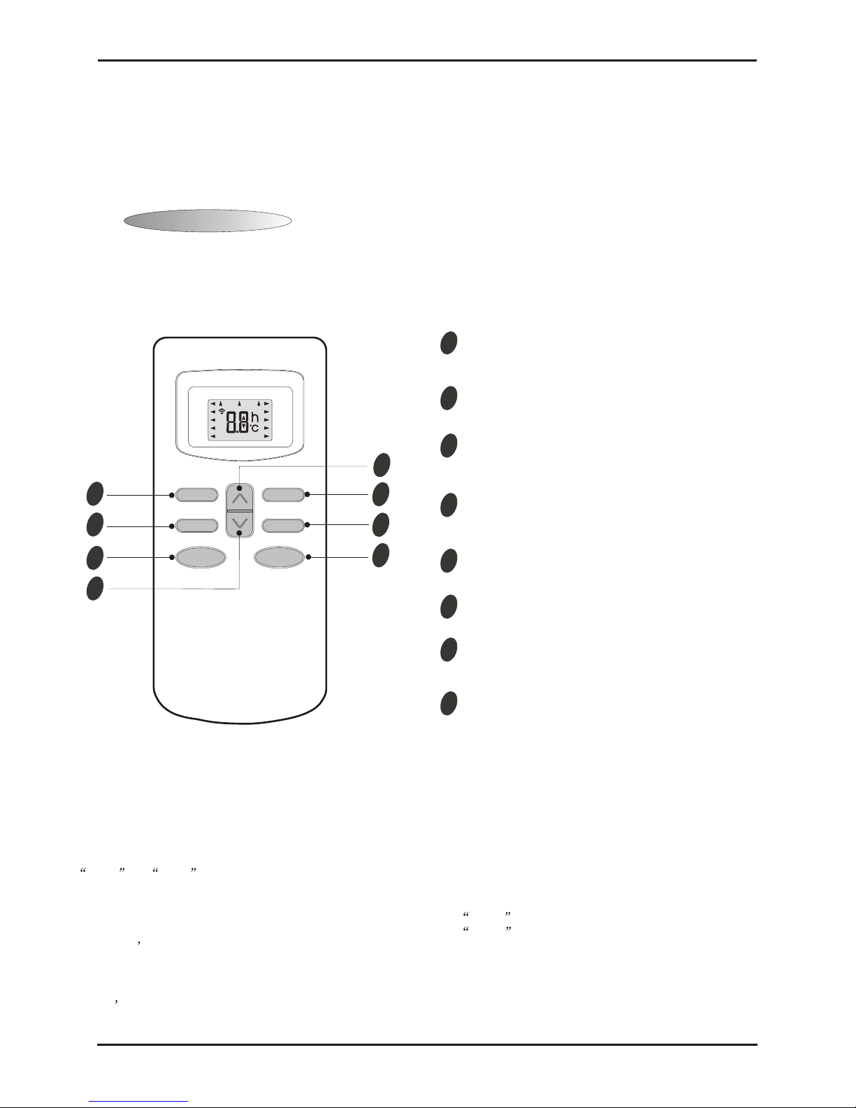
the display. You can now adjust the temperature with the ▲▼ button. Press the Timer button again to
display the time, which can now also be adjusted☆.If the Timer button is pressed again, the data is stored and
the remaining time(that the air conditioner will be in operation) will appear in the display.
☆Pressing the ON/OFF/RUN button instead of the Timer button deactivates the remote control.
Note: check that the TIMER INDICATOR on the indoor unit lights up after the timer has been set.
Press the Timer function to check the settings in the display.
13. EMERGENCY-TEST Operation
Whenthe EMERGENCY Operation switch is pressed once, COOLING modeis selected and if in 3secondsthe
EMERGENCY Operation switch is pressed again, HEATING mode is selected. Then pressed once again, the unit
is switch off.
When the remote controller is missing, has failed or the batteries run down, press the EMERGENCY Operation
switch on the front of the indoor unit. The unit will start.
The first 30 minutes of operation will be the test run operation. The operation is for servicing. The indoor fan runs
at high speed and the system is in continuous operation. The thermostat is ON and the timer is reset to normal.
After 30 minutes of test run operation the system shifts to AUTO COOLING/HEATING mode, and the indoor fan
runs in automatic speed. The operation continues unit the EMERGENCY operation switch is pressed or a button
on the remote controller is pressed, the normal operation will start.
NOTE: Do not press the EMERGEMCY Operation switch during normal operation.
14.AUTO RESTART Function (Option)
When the indoor unit is controlled with the remote controller, the operation mode, set temperature, and the fan
speed are memorized by the indoor electric control PCB. The AUTO RESTART function sets to work the
moment power has restored after power failure. Then, the unit will restart automatically.
15. Failure Display and Handling
a) The failure of the resistance of heat sensitive:
When the resistance of heat sensitive reads the temperature is lower than -50℃or over than 110℃that
judge the heat sensitive is bad.
b) The Outdoor Protection Control
When the system checks the signal from outdoor of the voltage is 0V, the system delay 1second to start for
check the signal again, if checks the signal of the voltage is 0V too, that the system not to star, or operates on
normal.
c) Failure Display
When the controller is failure, the buzzer will voice long for three times, and displays the failure from the
failure lamp.
d) Failure Code
If have the digital pipe that display the failure code for digital pipe, or display for the run lamp.
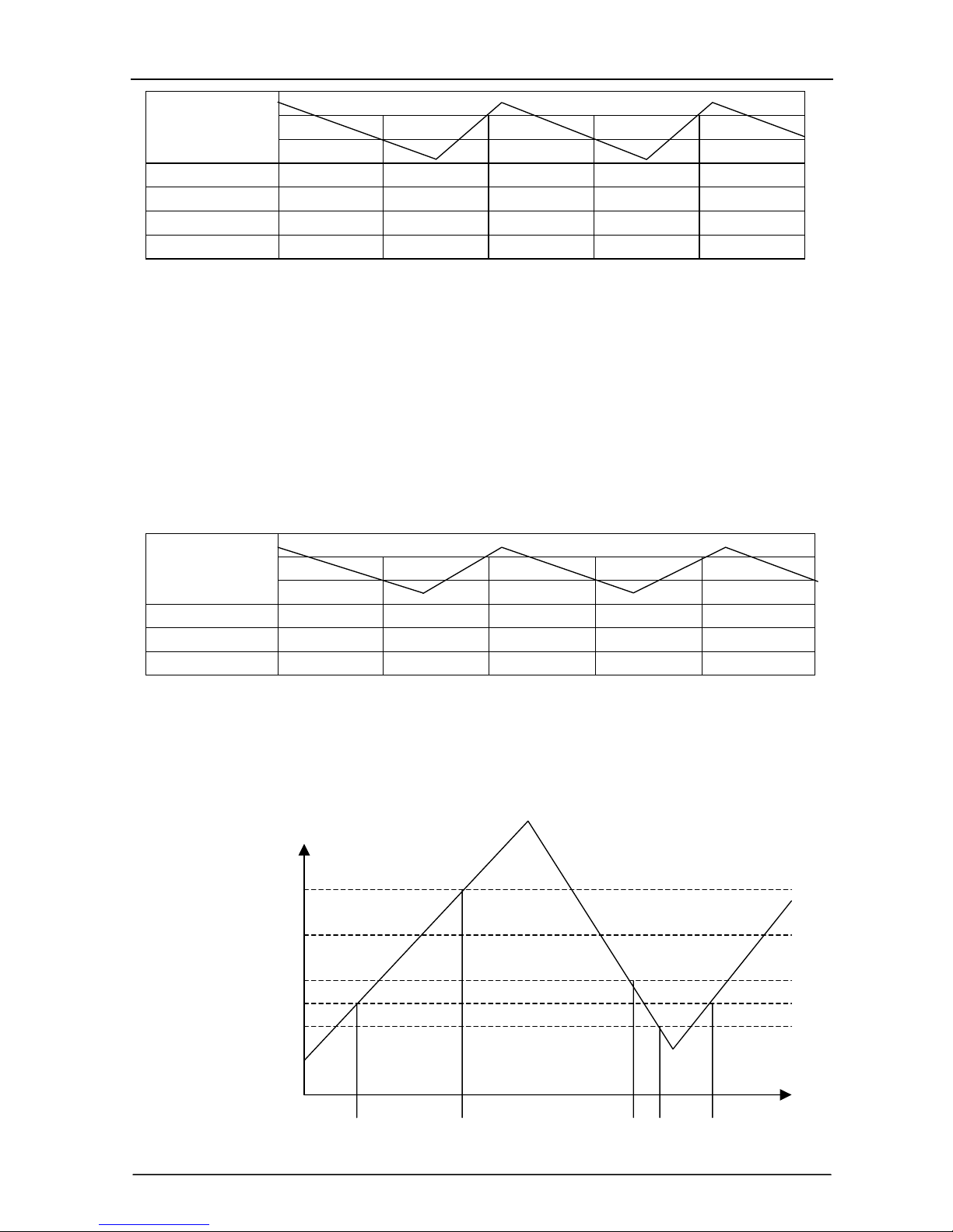
Type of failure The lamp flash Display of digital pipe
The failure of room temperature sensor Once/cycle E1
The failure of indoor pipe temperature sensor Twice/cycle E2
Outdoor protection function 5 times/cycle E5
The failure of indoor fan 6 times/cycleE6
e) Failure Handling
When the room temperature sensor or the indoor pipe temperature sensor is failure, the system will be
shut off, the compressor will be OFF, and the outdoor fan and the indoor fan will be OFF. The system
doesn’t receive the signal of remoter controller except the signal of shut off it. When the failure
eliminated, the controller can operate in normal mode. before this, presses the “ON/OFF” to start the
system, and it will operate in COOLING or HEATING for 30 minutes, and follows shut off. During

TCL Air Conditioner Service Manual
11
this, it displays the failure and the protection is failing. You must be give the electric again to operate it.
In the failure, you can operate the FAN mode.
When the outdoor protects in the COOLING or DRY, the outdoor unit stops, the indoor fan operates in
set speed ; and in the HEATING, the outdoor unit stops, the assistant thermistor stops, the indoor fan
operates in cold air prevention control. The system doesn’t receive the signal of remoter controller
except the signal of shut off it. When the system check the voltage is 220V and the delay control is
finished, it operates at normal again.
When the indoor fan motor is failure, the compressor is stopped, the outdoor fan and indoor fan is
stopped and display the failure. The system doesn’t receive the signal of remoter controller except the
signal of shut off it.
f) Display Of The Control
In the display board the lamp from left is the POWER lamp (Red), the SLEEP lamp(Yellow), the TIMER
lamp(Yellow), the RUN lamp(Green).
(7) When gives the control electric, the buzzer voices a long for 0.3 second per cycle.

TCLAir Conditioner Service Manual
12
WIRING DISGRAM
MODEL:TAC-24CF/E
INDOOR UNIT:
INDOOR WIRING DIAGRAM
DISPLAY CIRCUIT
RED
WHITE
TRANSFORMER
MAIN CONTROL PCB
CN1
RED
WHITE CN2
CN3
CN5
CN8
CN6
MS SWING MOTOR
M
~
~FAN MOTOR
CAPACITOR
FAN
WHITE
AC220V~
YLW/GRN
YLW/GRN
50Hz
L
N
BROWN
BLUE
YLW/GRN
BROWN
BLUE
YLW/GRN
WHITE
P3
P2
P1 L
NL
N
BOX
11
COMP
θ
(RT)
(IPT)
TH1TH2
θ
INDOOR UNIT OUTDOOR
UNIT
1130080198
OUTDOOR UNIT:
OUTDOOR WIRING DIAGRAM
COMPRESSOR
MOTOR
CM
CS(M)
R
WHITE RED BLUE
YLW/GRN
WHITE
RELAY
FAN MOTOR
BLUE
CAPACITOR
M
YELLOW
RED
WHITE
BLUE
RED
YLW/GRN
~
~
BROWN
1NL
BROWN
BLUE
YLW/GRN
WHITE
OUTDOOR UNIT
INDOOR UNIT
(1130080199)

TCLAir Conditioner Service Manual
13
MODEL: TAC-24CHF/E
INDOOR UNIT:
~
~
INDOOR WIRING DIAGRAM
CONTROL BOARD
RED
RED
WHITE
TRANSFORMER
MAIN CONTROL BOARD
CN1
CN2
COM.
N.O.
HEAT
L
N
CN8 CN5
CN3
SWING MOTOR
CAPACITOR
MS
FAN
M
FAN MOTOR
YLW/GRN
YLW/GRN
AC220~
50Hz
BROWN
BLUE
YLW/GRN
WHITE 1
YLW
YLW/GRN
RED
BROWN
BLUE
WHITE
RED
YLW
P1
P2
COMP
O-FAN
VALVE
P3
P4
P5
CN6
CN7
(RT) (IPT)
NTC (OPT)
TEMPERATURE
CONTROLLER
HEATER
RED BLUE
HEATER PROTECTOR
(NON ELECTRIC IC AUXILIARY HEATING
MODEL WITHOUT AUXILIARY HEATER) INDOOR UNIT
L
N
3
2
L
N
1
2
3
(1130080201)
OUTDOOR UINT:
OUTDOOR WIRING DIAGRAM
COMPRESSOR
(BUILD IN OR VISIBLE PROTECTOR)
MOTOR CAPACITOR
RED YLW
~
M
YLW/GRN
CM
~
CSR
WHITE RED
(M)
BLUE
BLUE
FAN MOTOR
(BUILD IN PROTECTION)
VALVE COIL
CN7
NTC
(OPT)
CONTACTOR
BLUE
WHITE
YLW/GRN
WHITE
RED
BLUE
BLUE
BROWNBROWN
BLUE
YLW/GRN
WHITE
RED
YLW
OUTDOOR UNIT
INDOOR UNIT
LN1
23
(1130080209)
LN1
23

TCLAir Conditioner Service Manual
14
EXPLOSION VIEW
MODEL: TAC-24CF/E
INDOOR UNIT:

TCLAir Conditioner Service Manual
15
EXPLOSION VIEW
MODEL: TAC-24CHF/E
INDOOR UNIT:

TCLAir Conditioner Service Manual
16
EXPLOSION VIEW:
MODEL: TAC-24CF/E
OUTDOOR UNIT:
1
2
3
54
6
7
9
10
11 13 14 15 16 17
8
18 19
20
21
22
23
24
25
26
27
28
12

TCLAir Conditioner Service Manual
17
EXPLOSION VIEW
MODEL: TAC-24CHF/E
OUTDOOOR:
1
2
3
4
5
6
7
8
9
10
11 12 13 14 15 16 19
17 18 20
21
22
23
24
25
26
27
28
29
30

TCLAir Conditioner Service Manual
18
Indoor Unit- TAC-24CF/E
No. Part No. Part Name Q’ty Remark
1 1070740403 Operation Panel 1
2 1070520117 Temperature Display Lens 1
3 1070520118 Display lens 1
4 1090520104 Display PCB 1
5 1070520102 Top Panel 1
6 1070520103 Horizontal Vane 1
7 1070520106 Vertical Vane 2
8 1070520148 Vertical Vane Connect Rod 1
9 1070520107 Horizontal Vane Connect Rod 3
10 1170010008 Stepping Motor 1
11 1150520101 Out Fan Casing Foam 1
12 1150520102 Heat Insulation Board 2
13 1074090101 Copper Pipe Cover 1
14 1200710102 Rubber Water Drainage1 1
15 1200710101 Rubber Water Drainage2
16 1210710101 Evaporator Assembly 1
17 1210520115 Right Plate 1
18 1210520113 Top Plate 1
19 1210520114 Left Plate 1
20 1070520101 Base 1
21 1170050002 Fan Motor 2
22 1070010008 Centrifugal Fan 2
23 1150520104 Volute Casing 1
24 1074060115 Lead Flow Circle 1
25 1080520105 Electrical Parts Box 1
26 1074020122
1074020914
Cable Clamp1
Cable Clamp2
1
1
27 1170200026 Terminal 1
28 1170100027 Fan Motor Capacitor
29 1170240002 Transformer 1
30 1090710301 Main PCB 1
31 1170520103 Pipe Temp. Sensor & Room
Temp. Sensor Assembly
1
32 1080520106 Electrical Parts Box Cover 1
33 1070520113 Left Grille 1
34 1070520111 Below Panel 1
35 1070520112 Right Grille 1
36 1070520149 Left Right Grille Buckle 2
37 1070520147 Air Filter 1

TCLAir Conditioner Service Manual
19
38 1150520103 Water Drainage
39 1080520103 Middle Supporter
40 1080520122 Heat Insulation Board Cover
41 1090010071 Remote Control
42 1073030303 Remote Control Supporter
43 1190060022 Base Carton
44 1190060023 Left Right Beehive Carton
45 1190060024 Middle U Beehive Carton
46 1190060025 Middle Cover Beehive Carton
47 1190060026 Base Beehive Carton
48 1190060016 Cabinet Carton
49 1170130002 Power Supply Cord
Not shown in Explosion
view

TCLAir Conditioner Service Manual
20
Indoor Unit- TAC-24CHF/E
No. Part No. Part Name Q’ty Remark
1 1070740403 Operation Panel 1
2 1070520117 Temperature Display Lens 1
3 1070520118 Display lens 1
4 1090520104 Display PCB 1
5 1070520102 Top Panel 1
6 1070520103 Horizontal Vane 1
7 1070520106 Vertical Vane 2
8 1070520148 Vertical Vane Connect Rod 1
9 1070520107 Horizontal Vane Connect Rod 3
10 1170010008 Stepping Motor 1
11 1150520101 Out Fan Casing Foam 1
12 1150520102 Heat Insulation Board 2
13 1074090101 Copper Pipe Cover 1
14 1200710102 Rubber Water Drainage1 1
15 1200710101 Rubber Water Drainage2
16 1210710101 Evaporator Assembly 1
17 1210520115 Right Plate 1
18 1210520113 Top Plate 1
19 1210520114 Left Plate 1
20 1070520101 Base 1
21 1170050002 Fan Motor 2
22 1070010008 Centrifugal Fan 2
23 1150520104 Volute Casing 1
24 1074060115 Lead Flow Circle 1
25 1080520105 Electrical Parts Box 1
26 1074060118 Cable Clamp 1
27 1170200010 Terminal 1
28 1170100027 Fan Motor Capacitor
29 1170240002 Transformer 1
30 1090710101 Main PCB 1
31 1170520103 Pipe Temp. Sensor & Room
Temp. Sensor Assembly
1
32 1080520106 Electrical Parts Box Cover 1
33 1070520113 Left Grille 1
34 1070520111 Below Panel 1
35 1070520112 Right Grille 1
36 1070520149 Left Right Grille Buckle 2
37 1070520147 Air Filter 1
38 1150520103 Water Drainage
This manual suits for next models
1
Table of contents
Other TCL Air Conditioner manuals

TCL
TCL TAC-09CHSA/XP User manual

TCL
TCL TAC-07CS User manual

TCL
TCL TCLWB05C User manual

TCL
TCL TCLSS09 User manual

TCL
TCL TACM2O-28HIA User manual

TCL
TCL AC12000E User manual

TCL
TCL TAC-09CSD/XAB1 User manual

TCL
TCL iQool-3MS9K9K9K Operating manual

TCL
TCL TAC-12CPA User manual

TCL
TCL TAC-09CHSD/XAA1I User manual

TCL
TCL ERA YA11I User manual

TCL
TCL TAC-09CHSA/GI User manual

TCL
TCL TAC-42CF User manual

TCL
TCL TFF-60HRA User manual

TCL
TCL TWC-15CR/UH (ES) User manual

TCL
TCL Free Match FMA-18I2HD/DVO User manual

TCL
TCL R32 User manual

TCL
TCL AC12000E User manual

TCL
TCL TAC-09CHSA/F6 User manual

TCL
TCL TAC-09CSD/XA81I User manual