manuals.online logo
Brands
  1. Home
  2. •
  3. Brands
  4. •
  5. YOKOGAWA
  6. •
  7. Controllers
  8. •
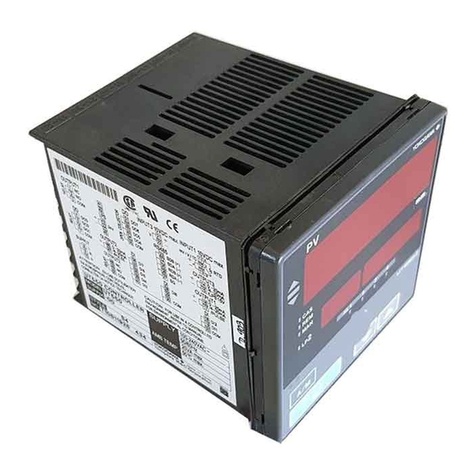
  9. YOKOGAWA UTAdvanced UT52A Manual

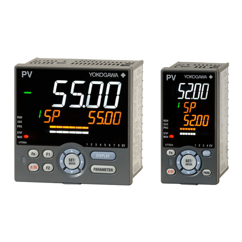
YOKOGAWA UTAdvanced UT52A Manual

Setup Procedure
UTAdvanced Quick Setting (pH Control)
TI 04L01L01-01EN
Foreword
The contents of this document are subject to change without prior notice as a result of improvements in performance or functionality.
Copying or reproduction by any means of all or any part of the contents of this document without permission is strictly prohibited.
Use of this document is at the users risk.
This document is subject to change without notice. TI 04L01L01-01EN
2011.12.16 1st Edition (YK)
Technical
Information
■Overview
This is an example of wiring and settings using the UTAdvanced Quick Setting function for "pH Control."
For more details, see the user's manual.
■Relevant models
Standard models of the UT52A and UT55A (if there are 2 types of pharmaceuticals, select the
heating/cooling model)
■System
■Wiring
Sampling can be controlled to interpolate dead time
Current input signal
4–20 mA
Current input signal
4–20 mA
Plant A waste liquid -->
Plant B waste liquid -->
Plant C waste liquid -->
Chemical dosing pump
pH meter
converter
0–14 pH
pH meter
sensor
Effluent
■Sampling control
■Nonlinear t
yp
e
Control gain is switched by the Gap Gain Control
function
Current input
4–20 mA
PV
Current
input
Power
supply -
+
203
Current output
4–20 mA
+
-
UT52A, UT55A Standard Models
pH meter
+
-
Current
output
4–20 mA
PV
Transmission
output
2/4
This document is subject to change without notice. TI 04L01L01-01EN 2011.12.16-00
■Settings
To set the sample PID control, input type (4 to 20 mA), and current control output (4 to 20 mA), set the
parameters below.
(1) Select the desired parameter with the UP or DOWN key
(2) Press SET/ENTER (the setting value blinks)
(3) Change the setting with the UP or DOWN key
(4) Press SET/ENTER to set the new value (the setting value stops blinking but remains
bright)
●Redoing the Quick Setting
Once functions are configured with the Quick Setting, the Quick Setting function
will not appear after you restart. However, you can redo the Quick Setting by
following the procedure below.
(1) Set the Quick Setting parameter QSM to ON, and re-engage power
(2) Set the PV input type parameter IN to OFF, and re-engage power
Press SET/ENTER to accept the "YES" option.
Quick Setting starts
First, the control type parameter CNT appears.
Set the CNT (control type) to S-PI (sample PI control).
OFF is displayed for IN (the PV input type).
Set IN (PV input type) to current signal: 4–20
(4–20 = 4.00 to 20.00 mA).
Set UNIT (PV input unit) to – (none). If necessary, use the unit label "pH."
START QUICK
SETTING
QSM YES
CONTROL TYPE
1.
2.
CNt S-PI
PV INPUT TYPE
3.
IN OFF
PV INPUT TYPE
4.
IN 4ー20
PV INPUT UNIT
5.
UNIt ー
Power
Quick Setting
start
3/4
This document is subject to change without notice. TI 04L01L01-01EN 2011.12.16-00
Set RH (maximum value of PV input range) to 20.00 mA (the initial value).
Set RL (minimum value of PV input range) to 4.00 mA (the initial value).
Set SDP (PV input scale decimal point position) to 2.
Set SH (maximum value of PV input scale) to 14.00 (pH).
Set SL (minimum value of PV input scale) to 0.00 (pH).
Set OT (output type selection) to 00.02: OUT terminal (current 4 to 20 mA).
Skip this parameter (not relevant).
Finally, EXIT is displayed. Select YES and press SET/ENTER to complete the
basic function setup and return to the operating screen. Or, you can select NO
to continue with the Quick Setting.
11.
13.
12.
10.
MAXIMUM
VALUE OF PV
INPUT RANGE
6.
RH 20.00
7.
FINISH
EXIt YES
MINIMUM
VALUE OF PV
INPUT RANGE
RL 4.00
CONTROL OUTPUT
CYCLE TIME
Ct30.0
OUTPUT TYPE
SELECTION
8.
0t00.02
9.
SdP2
SH 14.00
PV INPUT SCALE DECIMAL
POINT POSITION
MAXIMUM VALUE OF
PV INPUT SCALE
SL 0.00
MINIMUM VALUE OF
PV INPUT SCALE
4/4
This document is subject to change without notice. TI 04L01L01-01EN 2011.12.16-00
Revision Information
Document name: Setup Procedure: UTAdvanced Quick Setting (pH Control)
Document number: TI 04L01L01-01EN
First edition: December, 2011
Newly released

Other manuals for UTAdvanced UT52A

1

This manual suits for next models

1

Other YOKOGAWA Controllers manuals

YOKOGAWA UT Advanced UT32A User manual

YOKOGAWA

YOKOGAWA UT Advanced UT32A User manual

YOKOGAWA YS80 Series Manual

YOKOGAWA

YOKOGAWA YS80 Series Manual

YOKOGAWA SMARTDAC+ GX20 User manual

YOKOGAWA

YOKOGAWA SMARTDAC+ GX20 User manual

YOKOGAWA NEW GREEN SERIES User manual

YOKOGAWA

YOKOGAWA NEW GREEN SERIES User manual
YOKOGAWA UT351 User manual

YOKOGAWA

YOKOGAWA UT351 User manual

YOKOGAWA UT150L User manual

YOKOGAWA

YOKOGAWA UT150L User manual

YOKOGAWA YS1000 Series User manual

YOKOGAWA

YOKOGAWA YS1000 Series User manual
YOKOGAWA UTAdvanced UT32A Manual

YOKOGAWA

YOKOGAWA UTAdvanced UT32A Manual

YOKOGAWA Fluidcom S2 User manual

YOKOGAWA

YOKOGAWA Fluidcom S2 User manual

YOKOGAWA UTAdvanced UT52A User manual

YOKOGAWA

YOKOGAWA UTAdvanced UT52A User manual

YOKOGAWA UT320 User manual

YOKOGAWA

YOKOGAWA UT320 User manual

YOKOGAWA CX1000 User manual

YOKOGAWA

YOKOGAWA CX1000 User manual

YOKOGAWA UT321 User manual

YOKOGAWA

YOKOGAWA UT321 User manual

YOKOGAWA UT35A-L User manual

YOKOGAWA

YOKOGAWA UT35A-L User manual

YOKOGAWA UTAdvanced UT32A Manual

YOKOGAWA

YOKOGAWA UTAdvanced UT32A Manual

YOKOGAWA Fluidcom S2 User manual

YOKOGAWA

YOKOGAWA Fluidcom S2 User manual

YOKOGAWA UT75A User manual

YOKOGAWA

YOKOGAWA UT75A User manual

YOKOGAWA CX2000 Guide

YOKOGAWA

YOKOGAWA CX2000 Guide

YOKOGAWA UTAdvanced UT32A User manual

YOKOGAWA

YOKOGAWA UTAdvanced UT32A User manual

YOKOGAWA UP35A User manual

YOKOGAWA

YOKOGAWA UP35A User manual

YOKOGAWA YS170 User manual

YOKOGAWA

YOKOGAWA YS170 User manual
YOKOGAWA STARDOM FCN Manual

YOKOGAWA

YOKOGAWA STARDOM FCN Manual

YOKOGAWA UTAdvanced UT32A Manual

YOKOGAWA

YOKOGAWA UTAdvanced UT32A Manual

YOKOGAWA UT32A-R User manual

YOKOGAWA

YOKOGAWA UT32A-R User manual
Popular Controllers manuals by other brands

LSIS XGT Series user manual

LSIS

LSIS XGT Series user manual

SEW-Eurodrive MOVI-C Controller Power UHX85A manual

SEW-Eurodrive

SEW-Eurodrive MOVI-C Controller Power UHX85A manual

Festo CMMP Series manual

Festo

Festo CMMP Series manual

EMS EMS372 user manual

EMS

EMS EMS372 user manual

Christie Velvet CorePlus E600 user guide

Christie

Christie Velvet CorePlus E600 user guide

Peter electronic VersiStart i II Commissioning instructions

Peter electronic

Peter electronic VersiStart i II Commissioning instructions

Cisco Catalyst C9800-L Hardware installation guide

Cisco

Cisco Catalyst C9800-L Hardware installation guide

Emerson Bettis RPX Series Safety guide

Emerson

Emerson Bettis RPX Series Safety guide

VideoSys ODU user manual

VideoSys

VideoSys ODU user manual

EbV elektronik CETA 106 operating manual

EbV elektronik

EbV elektronik CETA 106 operating manual

Digital Monitoring Products X1 Series quick start guide

Digital Monitoring Products

Digital Monitoring Products X1 Series quick start guide

Mitsubishi FX2N-4AD-PT user guide

Mitsubishi

Mitsubishi FX2N-4AD-PT user guide

Dynamatic 4050 instruction manual

Dynamatic

Dynamatic 4050 instruction manual

artisan cFP-2200 Operating instructions and specifications

artisan

artisan cFP-2200 Operating instructions and specifications

ICT PRT-CTRL-DIN installation manual

ICT

ICT PRT-CTRL-DIN installation manual

Magtrol DSP6001 user manual

Magtrol

Magtrol DSP6001 user manual

PERIBIT SR-50 quick start

PERIBIT

PERIBIT SR-50 quick start

Arcus ACE-SXC manual

Arcus

Arcus ACE-SXC manual

manuals.online logo
manuals.online logoBrands
  • About & Mission
  • Contact us
  • Privacy Policy
  • Terms and Conditions

Copyright 2025 Manuals.Online. All Rights Reserved.