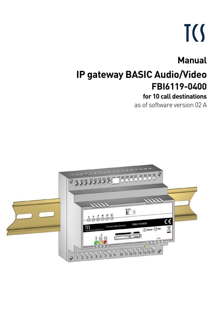
TCS FBI6119-0400 User manual

Product information
IP audio / video gateway BASIC
FBI6119-0400
for 10 call destinations
as of software version 02 A

2
Table ofcontents
Scope of delivery..........................................................................................................................................................3
introduction..................................................................................................................................................................3
Notes on this product information....................................................................................................................................................................... 3
Used symbols and warning notices .................................................................................................................................................................... 3
Further used symbols........................................................................................................................................................................................... 3
Safety instructions.......................................................................................................................................................4
General safety regulations ................................................................................................................................................................................... 4
requirements to protect against lightning ......................................................................................................................................................... 4
Note for video surveillance according to DIN 33450......................................................................................................................................... 4
Product description .....................................................................................................................................................5
Intended use ........................................................................................................................................................................................................... 5
Short description.................................................................................................................................................................................................... 5
Device overview...................................................................................................................................................................................................... 6
Indication and operating elements...................................................................................................................................................................... 6
Technical data......................................................................................................................................................................................................... 7
Mounting and installation ............................................................................................................................................8
DIN-rail mounting....................................................................................................................................................................................................................... 8
Dismantling from the DIN-rail .................................................................................................................................................................................................. 8
Connecting the lines.............................................................................................................................................................................................. 9
Connecting lines.......................................................................................................................................................................................................................... 9
Connecting the lines ................................................................................................................................................................................................................... 9
example circuit with WLAN home network .....................................................................................................................................................10
Initial operation..........................................................................................................................................................11
Settings on the device..........................................................................................................................................................................................11
Placing the video matching resistor .......................................................................................................................................................................................11
restart the device ......................................................................................................................................................................................................................12
reset network settings and passwords..................................................................................................................................................................................12
installation .................................................................................................................................................................12
static and dynamic IP addresses and DHCP service:............................................................................................................................................................12
Settings via configoTM ...........................................................................................................................................................................................13
(De-)Activate the DHCP client.................................................................................................................................................................................................. 14
Change password for user and/or admin..............................................................................................................................................................................14
Cleaning .....................................................................................................................................................................15
Conformity .................................................................................................................................................................15
Information on disposal.............................................................................................................................................15
Warranty ....................................................................................................................................................................15
Service........................................................................................................................................................................16

3
Scope of delivery
1 x FBI6119-0400
1 x jumper for matching resistor
1 x product information
introduction
Notes on this product information
This product information refers exclusively to qualified electricians.
The product information contains important notes on intended use, installation and initial operation. Please, keep the
product information at a suitable place, where it is easily accessible for maintenance and repair reasons.
All product information are available in the download area at www.tcsag.de .
For further information on commissioning see the manual FBI6119-0400 or consult your network ad-
ministrator. All manuals are available in the download area at www.tcsag.de .
Used symbols and warning notices
Symbol signal word Explanation
DANGER! The signal word describes an endangering with a high level of risk. Failure to observe this
warning will result in death or very serious injury.
WARNING! The signal word describes an endangering with a medium level of risk. Failure to observe this
warning could result in death or very serious injury.
CAUTION! The signal word describes an endangering with a low level of risk. Failure to observe this warn-
ing could result in a minor or moderate injury.
ATTENTION! The signal word indicates, that damages on equipment, environment and property can occur.
Further used symbols
important note or important information
video identification according to DIN 33450
►Step
cross reference For further information on this topic, see source
list, list entry 1 level
‐
list, list entry 2 level

4
Safety instructions
General safety regulations
Assembly, installation, commissioning and repair of electronic devices must be carried out by qualified
electricians.
Observe the latest regulations and standards for system installations.
WARNING! Danger to life due to electric shock
Observe the safety regulations according to DIN VDE 0100, when working on main power connections of
230 V.
When installing TCS:BUS systems the general safety regulations for telecommunication systems ac-
cording to VDE 0800 must be observed. Inter alia:
separated cable routing of high and low voltage lines,
minimum distance of 10 cm in case of a common cable routing,
use of separators between high and low voltage lines within shared cable ducts,
use of standard telecommunication lines, e.g. J-Y (St) Y with 0.8 mm diameter,
already existing lines (modernisation) with deviating cross-sections can be used in compliance with
the loop resistance.
requirements to protect against lightning
ATTEN-
TION! Device damage due to overvoltage.
By suitable lightning protection measures it has to be ensured that the electric voltage of 32 V DC at each
connection is not to be exceeded.
Note for video surveillance according to DIN 33450
Creating and saving video recordings can infringe personal rights.
Observe the current regulations and labelling requirements when installing and operating video com-
ponents.

5
Product description
Intended use
The FBI6119-0400 is a gateway between the TCS:BUS and IP networks. The FBI6119-0400 can exchange voice, vid-
eo, control functions and messages between TCS:BUS and IP networks. The FBI6119-0400 is the interface between
TCS:BUS system and network-compatible devices (computer, IP telephones, smartphones, tablets...). The device is
suitable for DIN-rail mounting (DIN EN 60715:2001-09) in a control cabinet with 6 SU. To set up the FBI6119-0400 an
external device (e.g. laptop) is required.
For applications, which differ from the intended use or goes beyond it, the manufacturer accepts no
liability.
Short description
audio:
half-duplex voice communication according to SIP standard
SIP call destinations via SIP account to a SIP server or via SIP direct calls (peer to peer)
up to 10 SIP door call destinations can be configured
up to 5 parallel calls per call destination can be configured
specific connection establishment to a SIP call destination due to control function at TCS:BUS device
up to 10 TCS:BUS call destinations can be called by SIP
integrated SIP server for up to 10 SIP call destinations
compatible XML file for IP telephones without H.264 (Snom, Auerswald, Gigaset)
video:
resolution QVGA (320 x 240) and VGA (640 x 480)
recall of single images via HTTP
MJPEG video stream via HTTP
H.264 video stream
image recording of the call via web interface
messages:
sending messages to compatible TCS:BUS devices via web interface
control functions:
up to 10 different control functions can be configured
triggering control functions via web interface
Configuration:
multi-lingual web interface (German, English, French and Italian)
restricted configuration with configoTM (e.g. changing the IP address)
firmware update (device software) via SD card
Hardware:
RJ45 connection for Ethernet
screw terminals for 6-wire TCS:BUS
slot for SD card (max. 2 GB)
visual status and error indication via LED

6
Device overview
1 connection terminals a, b, P, M, V1 and V2 6 WEL button (reset of network settings and passwords)
2 matching resistor (jumper for video IN) 7 button reset (device restart)
3 type label 8 LED red (error indication TCS:BUS)
4 SD card (not enclosed in the delivery) 9 LED yellow (error indication network and SD card
5 RJ45 socket with status LED (network connection) 10 LED green (indication for operational readiness)
Indication and operating elements
LED green OFF:
ON:
BLINKS (slowly, 1 Hz):
BLINKS (fast, 4 Hz):
device is out of service
operational readiness (the start process of the FBI6119-0400 is
finished)
WEL button is pressed (0 to 8 seconds)
network settings and password will be reset (press the WEL
button for 8 seconds)
LED yellow (error indi-
cation network)
ON:
BLINKS (slowly, 1 Hz):
BLINKS (fast, 4 Hz):
OFF:
start process of the device
error in the network
error SD card (unreadable)
no error in the network or with SD card
LED red (error indica-
tion TCS:BUS)
ON:
BLINKS (slowly, 1Hz):
OFF:
firmware update is updated
error in TCS:BUS
no error in TCS:BUS

7
Technical data
call signalling SIP compatible
audio
half-duplex (integrated echo suppressor)
codecs: G.711 (A/μ), G.726 832 kbps), GSM 6.10, iLBC, Speex
up to 5 clients can be called parallel
video encoding
encodes video from TCS:BUS to IP
JPEG single image, MJPEG and H.264 streaming
QVGA and VGA, up to 25 fps (adjustable)
up to 10 simultaneous streams
live stream via web interface
sending messages to TCS:BUS via web interface
control functions
door release and switching lights via SIP DTMF
up to 10 user-specific control functions can be configured (can
be triggered via web interface)
SIP call destinations
10 (in case of door calls)
200 (internal call via control function, if supported by the in-
door station)
TCS:BUS call destinations 10
integrated SIP server up to 10 entries
other functions
Image buffer
creating XML file for notify of compatible VoIP telephones
without H.264 (e.g. Snom, Gigaset, Auerswald)
visual status and error indication via LEDs
IP address via configoTM adjustable
multi-lingual web interface
interfaces
SD card (max. 2 GB), RJ45 connection, 6-wire TCS:BUS via
screw terminals
operating voltage Vmin 15 V DC – Vmax 28 V DC
input current in resting position I(a) = 0.1 mA, I(P) = 200 mA
max. input current: I(Pmax) = 250 mA
degree of protection IP20
housing plastics
DIN-rail housing 6 SU according to DIN 43880 for DIN-rail mounting
(DIN EN 60715)
dimensions (in mm) H 90 x W 104 x D 70
acceptable ambient temperature 0 °C … + 40 °C

8
Mounting and installation
Ensure when determining the installation site that the FBI6119-0400 must be connected to the network
via a LAN cable.
DIN-rail mounting
►Put the FBI6119-0400 on the DIN-rail (1).
►Snap in the FBI6119-0400 with slight pressure (2).
Check if the locking mechanism is securely engaged (ill. 2).
Fig. 1: DIN-rail mounting
Fig. 2: Engaging
Dismantling from the DIN-rail
►Press the locking mechanism downwards with a screwdriver (1).
►Pull off the FBI6119-0400 from the bottom site of the DIN-rail and
lift it off (2).
Ill. 3: dismantling from the DIN-rail

9
Connecting the lines
Connecting lines
connection terminals:
acceptable cross section (diameter) 0.08 … 0.82 mm2(Ø 0.32 … 1.0 mm)
max. number of wires per terminal contact 2 x 0.8 mm, 3 x 0.6 mm
Connect further wires by using auxiliary terminals.
Use only connecting lines made of the same material and with the same diameter within one terminal
contact.
network connection:
patch cable RJ45 CAT.5e FTP 8-pin
Connecting the lines
►Strip the lines.
►Connect the lines (a, b, P, M, V1 and V2) according to the labelling
(1) (ill. 4).
►Fix the lines by using the slot screwdriver (enclosed in the deliv-
ery).
►Connect the RJ45 interface at the FBI6119-0400 and your network
by using a patch cable (2).
Observe the example circuit on page 10.
Fig. 4: type label
Fig. 5: Connecting the lines

10
example circuit with WLAN home network
Fig. 6: Example circuit

11
Initial operation
Install the devices of the system completely
Proof the a-, b- and P-wire against each other for short-circuits
V1 and V2 must not be connected with the P-, a- or b-wire
Observe the polarity when connecting the video wires V1 (+) and V2 (−)
Switch on the mains voltage
We are continually improving our products. We recommend to visit our homepage regularly and look for
software updates for your device.
Detailed information on our terms of service for TCS IP-enabled systems you'll find at:
http://www.tcsag.de/fileadmin/user_upload/TCS_DE/Metanavigation/Service_Support/Servicebedingun
gen-IP_uk.pdf.
Settings on the device
Placing the video matching resistor
If the device is installed at the end of a TCS:BUS video
strand, the jumper for the video matching resistor must
be set.
Ex works the video matching resistor is placed in the
position
OFF
.
►Pull off the jumper (video matching resistor) from the position
OFF
.
►Place the jumper on the position
ON
(ill. 8).
Fig. 7: Placing the matching resistor

12
restart the device
►Shortly press the
reset button
with a pointed object (ill. 9). The
device will restart.
The restart takes around 60 seconds. The LEDs remain off
during the boot procedure.
Fig. 8: device restart (reset button)
reset network settings and passwords
If the web interface is not available, you can reset the network set-
tings as well as the passwords to the factory setting.
The telephone book or project specific data are not delet-
ed.
Use the web interface for a complete upload of the facto-
ry settings.
►Keep the WEL button pressed (8 s) by using a pointed object until
the green LED blinks slowly at first and then fast (ill. 10).
►Release the WEL button . The network settings and password will
be reset.
The restart takes around 60 seconds. The LEDs remain off
during the boot procedure.
Fig. 9: reset network settings and passwords (WEL button)
installation
Installing an IP network is very complex and requires appropriate background knowledge because of many inter-
connected parameter and settings. Please contact your network administrator.
static and dynamic IP addresses and DHCP service:
Each device within an IP network needs its own IP address. In simple systems, all devices are located
within a local IP address range and within the same subnet. Thus, all devices can communicate with
each other without routing. Within home networks the scheme is as follows:
192.168 . xxx . xxx
subnet mask
The subnet mask divides the IP address into a network part (including the subnet) and into a host part
(individual number of a device within the subnet). For the scheme mentioned above the subnet mask is
always 255.255.255.0.
Why using static or dynamic IP addresses?
number of the subnet
defines the allocation to a subnet, must
be the same for all devices within one
subne
t
individual number of the device in the
subnet
each device needs its own number for identifi-
cation This number must not be assigned
twice within one subnet.
Prefix for local IP address-
es according to class C of
the convention RFC 1918

13
Usually a fixed IP address is assigned manually to a device that is providing a service within the network
(server). Devices that are only requesting service (clients), thus can be reached under this IP address. For
the clients it is recommended to use the automatic assignment of IP addresses per DHCP service. The
DHCP service manages a pool of IP addresses for dynamic allocation. Within home networks such a ser-
vice is available by default. Instead of its activation there is no further configuration necessary at the de-
vice. For service devices (e.g. FBI6119-0400) a manual management is necessary. Example: To receive
the video image, the smartphone needs to know under which IP address the front-door station can be
reached. The smartphone can have a dynamic IP address, because the device itself provides no service.
For further information on installation refer to manual. All manuals are available in the download area at
www.tcsag.de .
Settings via configoTM
The following configurations can be set with configoTM :
The configuration of the FBI6119-0400 is feasible as of configo version 1.9.0.8 .
(De-)Activate the DHCP client
Indicating and changing of:
‐ IP address
‐ subnet mask
‐ DNS server
‐ standard gateway
‐ admin and user password
Ex works the following settings are available for the FBI6119-0400:
DHCP deactivated
IP address 192.168.178.202
subnet mask 255.255.255.0
gateway 192.168.178.1
DNS server 192.168.178.1
user and admin password 1.234
If DHCP is activated, the current IP address of the FBI6119-0400 can be read-outTM by using configo.

14
(De-)Activate the DHCP client
Es works the FBI6119-0400 is delivered with deactivated
DHCP client. IP address ex works: 192.168.178.202 (ill. 10).
►Start the configo softwareTM on your PC.
►Set resp. remove the checkmark from the box (De-)Activate
DHCP.
►Update the EEPROM of the FBI6119-0400.
For further information on configoTM refer to help function of
the program.
If the DHCP client is deactivated, you have to assign a
valid IP address for the FBI6119-0400 manually.
For further information refer to manual FBI6119-0400 or
consult your network administrator. All manuals are
available in the download area at www.tcsag.de .
Fig. 10: DHCP client is activated
Fig. 11: DHCP client is deactivated
Change password for user and/or admin
►Click e.g. the option
Password "User“
A new window will open (ill.
13).
►Enter your old password into the text field
Old password
.
►Enter your new password into the text field
New password
.
►Repeat your entry in the text field
Repeat new password
.
►Click
OK
.
►Update the EEPROM of the FBI6119-0400.
For further information on configoTM refer to help function of
the program.
Fig. 12: Changing the password
Ill. 13: Create new password

15
Cleaning
ATTEN-
TION! Loss of function due to short-circuit and corrosion.
Water and cleaning agents can enter the device. Electronic elements can get damaged due to short-
circuit or corrosion.
Avoid water and detergents from entering the device! Clean the device with a dry or slightly wet cloth.
ATTEN-
TION! Damages on the surface of the device
Abrasive or scratching detergents damage the surface of the device.
Do not use any abrasive detergents! Remove strongerstains with a pH neutral household cleaner.
Conformity
Declarations of conformity are available for download under www.tcsag.de.
Information on disposal
Dispose the device separately from domestic waste via a collection point for electronic scrap. Ask your
county administration for the responsible collection point.
Dispose the parts of the packaging in collecting tanks for cardboard and paper resp. plastics.
Warranty
We offer a simplified processing in case of warranty for qualified electricians.
Please contact the TCS HOTLINE under [email protected].
Our standard terms and conditions of sale you'll find under www.tcsag.de.

16
Service
Please send your questions and inquiries to
Headquarters
TCS TürControlSysteme AG, Geschwister-Scholl-Str. 7, 39307 Genthin | Germany
FON: +49 (0) 3933/8799-10, FAX: +49 (0) 3933/879911, www.tcsag.de Subject to technical changes.
TCS Hotline Germany
time of printing: 06/2015
PI_FBI6119-0400 7 A
Other manuals for FBI6119-0400
1
Table of contents
Other TCS Gateway manuals