TCS QWL4.1 User manual

2800 Laura Lane • Middleton, WI 53562 |800.288.9383 |www.tcsbasys.com 202311
Building Automation Systems
|Installation Manual
QWL4.1
Integrated Building Manager Panel

23
2800 Laura Lane • Middleton, WI 53562 |800.288.9383 |www.tcsbasys.com Building Automation Systems
23
Introduction ........................................................................................................3
Installation..........................................................................................................4
Glossary of Terms ..................................................................................................................................4
Material List.............................................................................................................................................6
Wall Mounting........................................................................................................................................6
Wiring Access Port ................................................................................................................................6
Factory IP Network Address Configuration......................................................................................6
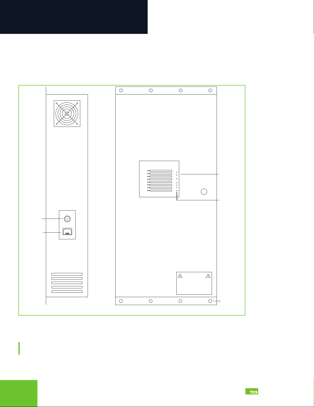
Power and Communication Connections ........................................................................................ 7
Input Wiring............................................................................................................................................8
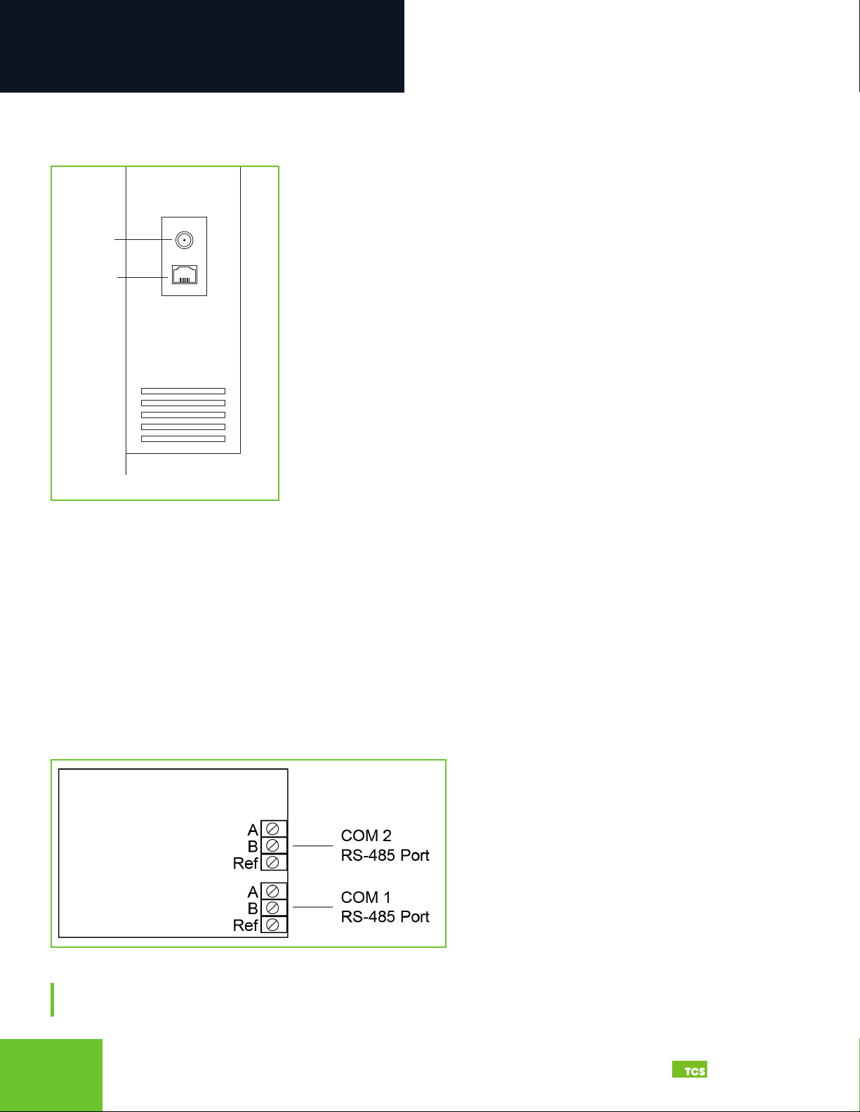
RS-485 Controller Network Wiring & Setup ..................................................................................10
Network Wiring..............................................................................................................................................................10
Three-Wire Network Wiring........................................................................................................................................ 11
Two-Wire Network Wiring........................................................................................................................................... 12
Startup ...................................................................................................................................................13
Troubleshooting ..................................................................................................................................14
Power LED Does Not Light Up .................................................................................................................................... 14
No Communications with Controllers on the Network ........................................................................................ 14
No LAN Link to the Internet ........................................................................................................................................ 14
No Communication with RS-485 Ports (COM 1 and 2), Ubiquity Time-out, or No Data................................. 14
Gateway Conguration ......................................................................................16
Introduction to Gateway Configuration .........................................................................................16
Gateway Configuration Via Laptop............................................................................................................................ 16
Gateway Configuration via CLI................................................................................................................................... 21
Lighting/Pulse Meter Programming....................................................................24
Introduction to Lighting/Pulse Meter Programming .................................................................. 24
Pulse Meter Module Programming ..................................................................................................27
Meter Types .................................................................................................................................................................... 27
Appendices.......................................................................................................29
Appendix A: Local Management Port ............................................................................................. 29
Connection Setup .........................................................................................................................................................29
Appendix B: Revert Back to DHCP Settings....................................................................................35
Appendix C: Monitor and Keyboard ............................................................................................... 39
Connection Setup .........................................................................................................................................................39
Appendix D: Configuring Local Management Port as a Fail-Over Port.................................... 40
Fail-Over Port Configuration Via Internal Gateway................................................................................................40
Fail-Over Port Configuration Via CLI.........................................................................................................................42
Appendix E: Installing and Using TCS Insight Software .............................................................. 44
Contents

32800 Laura Lane • Middleton, WI 53562 |800.288.9383 |www.tcsbasys.com Building Automation Systems
3
Congratulations on choosing the TCS QWL4.1 Integrated Building Manager! For facilities managers responsible for
multiple sites across multiple geographic locations, the QWL4.1 Integrated Building Manager provides the tools to
increase energy savings, reduce operational and maintenance costs, provide better indoor air quality, and increase
occupant comfort.
The QWL4.1 Building Manager utilizes Ubiquity Cloud™ building management technology, a QD2040d Panel Gateway, an
SLQ218 Lighting Controller, and an SEQ100 Pulse Meter for continuous monitoring of electrical, gas, and water usage.
This manual includes all the information you will need to properly install and set up your QWL4.1 . It is divided into four
sections:
• Installation: The Installation section covers the initial mounting, input wiring and connection of the QWL4.1 to your
network of control devices. Read and throughly understand this section before beginning the actual installation of the
unit.
• Gateway Conguration: Most units come with the Building Manager’s Gateway precongured; if your unit’s Building
Manager was precongured by TCS, you can skip this section. However, some customers order their units without
being congured beforehand; for those customers, we include this section which contains essential information
necessary to set up the Building Manager’ Gateway.
• Lighting/Pulse Meter Programming: Lighting and pulse meter programming can be accomplished via Ubiquity Cloud.
Read the Lighting/Meter Programming section to learn the basics of properly programming the SLQ218 Lighting
Controller and the SEQ100 Pulse Meter to your site specications.
• Appendices: Appendices A, B, and C provide supplemental information regarding connecting a laptop or keyboard
and monitor directly to the QWL4.1 for local programming and/or conguring the components of the QWL4.1.
Appendix D provides information on using TCS Insight software, a service tool that can be used to program the QWL
locally. TCS Insight is a very powerful service tool that should be used only by trained technicians.
If you have any questions regarding your QWL4.1 or your network, do not hesitate to contact TCS Technical Support at
800.288.9383, ext. 2.
Introduction

45
2800 Laura Lane • Middleton, WI 53562 |800.288.9383 |www.tcsbasys.com Building Automation Systems
45
Installation
Glossary of Terms
Astronomical Time Clock/Time: Timekeeping settings based on the sunrise and sunset at the geographical location of
the unit.
Baud Rate: The speed with which a device communicates over a network connection.
BTU: British Thermal Unit. A measure of the quantity heat required to raise the temperature of one pound of liquid water
one degree Fahrenheit.
Cellular Modem: A type of modem that allows a personal computer or a router to receive Internet access via a mobile
broadband connection instead of using telephone or cable television lines.
CLI: Command Line Interface. A shell for interactive access to operating system functions or services.
Cloud/Cloud-based: “The cloud” refers to servers that are accessed over the Internet, and the software and databases
that run on those servers. By using cloud computing, users and companies don’t have to manage physical servers or run
software applications on their own machines.
CT Value: Current Transformer Value. The value of the current wired to the meter, usually expressed in amps.
Current Transducer: A device which converts current into a proportional industrial standard electrical signal.
DHCP: Dynamic Host Conguration Protocol. A network management protocol used on Internet Protocol local area
networks. A DHCP server must be present on the network.
DNS: Domain Name System. A hierarchical and decentralized naming system for computers, services, or other resources
connected to the Internet or a private network.
Dry Contact: A secondary set of contacts of a relay circuit which does not make or break the primary current being
controlled by the relay.
EEMS: Enterprise Energy Management System. A system of computer-aided tools used by operators of electric utility
grids to monitor, control, and optimize the performance of the generation or transmission system.
Firewall: A technological barrier designed to prevent unauthorized or unwanted communications between computer
networks or hosts.
Gateway: The node in a computer network that passes trafc from a local network to other networks or the Internet (router).
IP: Internet Protocol. A set of rules for sending data across a network
kW: Kilowatt. A unit of electrical power. This unit equals 1000 watts. The kW is typically used to express the output power
of electric motors, tools, machines, and heaters.
kWh: Kilowatt-hour. A unit of energy equal to 3600 kilojoules. The kWh is commonly used as a billing unit for energy
delivered to consumers by electric utilities.
LAN: Local Area Network. A network that interconnects computers within a limited area such as a residence, school,
laboratory, university campus or ofce building.[
LED: Light Emitting Diode. A semiconductor light source that emits light when current ows through it.
MAC Address: Media Access Control Address. A unique identier assigned to a Network Interface Card (NIC) for use in
communications within a network segment.
Modbus: A standard data communication protocol for use in programmable logic controllers, thermostats, and similar
devices connected to the same cable or Ethernet network.
NIC: Network Interface Card. A circuit board or chip, which is installed on a computer so that it can connect to a network.
Polling: The process where a computer or controlling device waits for an external device to check its readiness or state.
Proxy/Proxy Server: A server application or appliance that acts as an intermediary for requests from clients seeking
resources from servers that provide those resources.

52800 Laura Lane • Middleton, WI 53562 |800.288.9383 |www.tcsbasys.com Building Automation Systems
5
Installation
RS-485: A networking standard which denes he electrical characteristics of drivers and receivers for use in serial
communications systems.
TCP: Transmission Control Protocol. A standard that denes how to establish and maintain a network conversation
through which application programs can exchange data.
TCP/IP: Transmission Control Protocol/Internet Protocol. A set of standardized rules that allow computers to
communicate on a network such as the internet.
UI: User Interface. The space where interactions between humans and computers occur, e.g., keyboard, mouse, monitor.
USB: Universal Serial Bus. A standardized plug and play interface that allows a computer to communicate with peripherals
and other devices.
WAN: Wide Area Network. A telecommunications network that extends over a large geographic area for the primary
purpose of computer networking.

67
2800 Laura Lane • Middleton, WI 53562 |800.288.9383 |www.tcsbasys.com Building Automation Systems
67
Installation
Material List
• QWL4.1 Integrated Building Manager Panel
• External Power Supply
Wall Mounting
The QWL4.1 is designed for wall mounting using four #10 pan head screws.
The unit MUST be powered down while mounting to the wall.
When selecting a location to mount the QWL4.1 , be sure to allow space for cable connections.
Locate the QWL4.1 away from excessive dust, heat sources, moisture or direct sunlight. The ideal environment is a server
room. The temperature of the room should not exceed 77ºF (25ºC); good ventilation is mandatory to provide sufcient air
cooling.
Wiring Access Port
The QWL. 4.0 comes with a one-inch wiring access port pre-drilled in the top of the unit. Drilling into the unit to add
additional wiring access ports is at your own risk. Use caution when drilling into the unit; be sure to capture all metal
shavings.
The unit MUST be powered down while drilling into the unit.
Factory IP Network Address Conguration
The QWL4.1 is typically purchased pre-congured to customer-specic IP networks and no additional software
conguration is required. If your QWL4.1 was purchased without pre-conguration, it will be shipped with DHCP client
enabled.
The IP network conguration page is accessible through a web browser via a computer, e.g., a laptop, that is physically
connected to the unit with a standard RJ-45 Ethernet cable. Contact your network administrator to determine the local IP
address (refer to the MAC address available on the product label).

72800 Laura Lane • Middleton, WI 53562 |800.288.9383 |www.tcsbasys.com Building Automation Systems
7
Installation
Power and Communication Connections
Make the following power and communication connections:
Power: Attach the included power supply to the side of the unit and insert the plug into a 120VAC outlet. Upon connection,
the unit should power up automatically. If it does not, press the Reset button located on the front Indicator Panel once to
restart the unit.
Exterior views
Cloud Connectivity Ethernet Port: Connect an Ethernet cable to the Ethernet port on the side of the QWL4.1 . Connect the
other end of the cable to your network switch port as determined by your local network administrator or IT department.
NOTE: If using a cellular modem provided by TCS, connect the Ethernet cable to the LAN port on the modem (contact
TCS Technical Support at 800.288.9383, ext. 2 for additional information).
CH|ON|DESCRIPTION
WARNING
LOW VOLTAGE PANEL:
24VAC
50/60 Hz ONLY
1
2
3
4
5
6
7
8
CPUALARMWIRELESS POWER
RESET RX TX
Power
Ethernet
Side View Front View
Indicator
Panel
Mounting
Holes
Reset
Button

89
2800 Laura Lane • Middleton, WI 53562 |800.288.9383 |www.tcsbasys.com Building Automation Systems
89
Installation
Interior view of boards and wiring connections Closeup of Ubiquity Cloud gateway ports
Input Wiring
NOTE: The Local Management Ethernet Port (L) on the side of the Ubiquity Cloud Gateway is used only for local onsite
management of the QWL4.1 device. Optionally, this port can be configured as secondary Internet fail-over port (see
Appendix D: Configuring Local Management Port as a Fail-Over Port on page 40 ).
COM Ports (RS-485 Network): Connect up to two RS-485 Networks to the inputs on Com Port panel or on the Serial Board
adjacent to the Gateway. (see RS-485 Controller Network Wiring & Setup on page 10).
USB Ports 1 – 4: As an option, you can connect up to 64 RS-485 controller networks via the four USB ports on the side of
the Ubiquity Cloud Gateway, by using QD1010 USB-to-RS-485 converters (not included).
USB
CABLE
USB
CABLE
ETHERNET
CABLE
Not Used
Not Used
USB PORT 2
USB PORT 1
USB PORT 4
USB PORT 3
LC ETHERNET 2ETHERNET 1
POWER
(12VDC)
HDMIDP
Not Used
Not Available
Not Used
Management Port
Optional RS-485
Input (TCSBus Only)
Interior View
Digital Inputs
Pulse Meter Inputs
Ubiquity Cloud
Gateway Ports
COM 1 RS-485
Inputs
COM 2 RS-485
Inputs
Analog Inputs
USB PORT 2
USB PORT 1
USB PORT 4
USB PORT 3
LC ETHERNET 2ETHERNET 1
POWER
(12VDC)
HDMIDP

92800 Laura Lane • Middleton, WI 53562 |800.288.9383 |www.tcsbasys.com Building Automation Systems
9
Installation
NOTE: Do not install line voltage devices (120VAC or greater) within this panel.
The QWL4.1 is comprised of the following components:
• Ubiquity Cloud Gatewayr
• SLQ218 Lighting Controller
• SLQ100 Electrical Pulse Meter
These components accept the following inputs:
• SLQ218 Lighting Controller:
⸰Eight dry contact/digital inputs
⸰ Two 0 – 5VDC analog inputs
Closeup of lighting controller inputs
• SLQ100 Electrical Pulse Meter:
⸰Four pulse meter inputs
Closeup of pulse meter inputs
DIGITAL INPUTS
ANALOG INPUTS
Pulse Meter Inputs
Z1 – K/Y1
Z2 – K/Y2
Z3 – K/Y3
Z4 – K/Y4

10 11
2800 Laura Lane • Middleton, WI 53562 |800.288.9383 |www.tcsbasys.com Building Automation Systems
10 11
Installation
• Ubiquity Cloud Site Building Manager:
⸰ Power from a 120VAC @ 60Hz to 12VDC power supply module (included)
Closeup of side view of QWL4.1
RS-485 Controller Network Wiring & Setup
The QWL4.1 can handle as many as 64 connected controllers on each port, including COM and serial ports. All
controllers connected to the network must be programmed with the same communication baud rate as well as a unique
communication address from 0 to 255, excluding 248. The baud rate is programmed onsite locally through the monitor
and keyboard, or through remote access through the network. On controllers with displays, this can be done from the
controller using its keypad and display, by using TCS Insight software, or by calling TCS Technical Support (800.288.9383,
ext. 2). TCS Technical Support can access the QWL4.1 online and change the address of a controller.
Network Wiring
The QWL4.1 has a serial board with two RS-485 ports that will accept Modbus and TCSbus Connections. These are the
recommended ports to use for your controller networks.
Recommended RS-485 port locations on serial board
NOTE: There is an additional RS-485 port on the Lighting Control/Pulse Meter Panel labelled “External RS-485”; however,
that port will only accept TCSbus.
CH|ON|DESCRIPTION
WARNING
LOW VOLTAGE PANEL:
24VAC
50/60 Hz ONLY
1
2
3
4
5
6
7
8
CPUALARMWIRELESS POWER
RESET RX TX
Power
Ethernet
Side View
Front View
Indicator
Panel
Mounting
Holes
Reset
Button

11 2800 Laura Lane • Middleton, WI 53562 |800.288.9383 |www.tcsbasys.com Building Automation Systems
11
Installation
Use 22 AWG, twisted shielded two-conductor or three-conductor cable for network wiring. Network wiring should start
at one controller and go to the next and then go to the next, until the nal controller is reached. Wiring is such that all “A”
wires are connected to “A” wires, all “B” wires are connected to “B” wires, and all “REF” wires are connected to “REF” wires.
NOTE: “A” refers to the negative (–) RS-485 connection and “B” refers to the positive (+) RS-485 connection.
A 120 Ω terminating resistor should be placed at each of the two ends of the network directly across the “A” and “B” wires.
• If the QWL4.1 will be at one end of the network, hard-wire a 120 Ω terminating resistor across the “A” and “B” terminals
of the QWL4.1 (See Three-Wire Network Wiring on page 11).
• If the QWL4.1 will be in the middle of the network, do not wire in the terminating resistor on the QWL4.1 terminal block
Connect one end (ideally the furthest end from the QWL4.1) of the shield wire of the network wiring to earth ground.
NOTE: If you encounter time-out errors, contact TCS Technical Support (800.288.9383, ext. 2).
Three-Wire Network Wiring
Follow this wiring diagram for all three-wire systems (this is common).
NOTES: In the middle of the network, all network wiring shields should be twisted together and taped off to prevent
accidental grounding. More than one ground on the network wiring can result in communication failure.
A maximum of two terminating resistors can be used.
QWL4.1 at end of the network.
QWL4.1 in the middle of the
network.
3
2
Shielded, twisted three-conductor
communications wiring with one end
earth grounded. (120 Ω balancing
resistors provided.)
Shielded, twisted three-conductor com-
munications wiring with one end earth
grounded. (120 Ωbalancing resistors
provided.)
4
NOTES:
1. If using more than 64 controllers,
use the second RS-485 port or
additional QD1010 adapters.
2. Each controller must use the
same baud rate and be assigned
a unique address.
1
A
B
REF
Shield
A
B
REF
A
B
REF
Earth Ground
Only at one end
Drain
Wire
Last in Daisy Chain
120Ω
Terminating
Resistor
COM 1
REF AB
Drain
Wire
120Ω
Terminating
Resistor
A
B
REF
A
B
REF
A
B
REF
Last in Daisy Chain
Shield
Last in Daisy Chain
Earth Ground
Only at one end
120Ω
Terminating
Resistor
A
B
REF
A
B
REF
A
B
REF
Shield
Drain
Wire
COM 1
REF REF
AA
BB
120Ω
Terminating
Resistor
12
3
3
4
44
COM 1
REF A
B
COM 1
REF A
B

12 13
2800 Laura Lane • Middleton, WI 53562 |800.288.9383 |www.tcsbasys.com Building Automation Systems
12 13
Installation
QWL4.1 at end of the network.
QWL4.1 in middle of the network.
1 3
2
Shielded, twisted two-conductor
communications wiring with one end
earth grounded. (120 Ω balancing
resistors provided.)
Shielded, twisted two-conductor com-
munications wiring with one end earth
grounded. (120 Ωbalancing resistors
provided.)
4
NOTES:
1. If using more than 64 control-
lers, use the second RS-485 port
or additional QD1010 adapters.
2. Each controller must use the
same baud rate and be assigned
a unique address.
Two-Wire Network Wiring
Follow this wiring diagram for two-wire (Modbus) wiring systems (this is not common).
Two-wire diagram
A
B
Shield
A
B
A
B
Earth Ground
Only at one end
Drain
Wire
Last in Daisy Chain
120Ω
Terminating
Resistor
COM 1
REF AB
Drain
Wire
120Ω
Terminating
Resistor
A
B
A
B
A
B
Last in Daisy Chain
Shield
Last in Daisy Chain
Earth Ground
Only at one end
120Ω
Terminating
Resistor
A
B
A
B
A
B
Shield
Drain
Wire
COM 1
REF REF
AA
BB
120Ω
Terminating
Resistor
12
3
3
4
44
COM 1
REF A
B
COM 1
REF A
B

13 2800 Laura Lane • Middleton, WI 53562 |800.288.9383 |www.tcsbasys.com Building Automation Systems
13
Installation
Startup
1. Verify all RS-485 connections from the controller network to the QWL4.1 are complete.
NOTE: Refer to Power and Communication Connections on page 7 for steps 2 through 5 below.
2. Verify that all 24V power wiring to the controller network has been completed; all controllers are powered on and
each controller has been programmed with a unique RS-485 address.
3. Connect one end of the Ethernet cable to the Ethernet port 1 (C) on the QWL4.1 , and the other end to the network
port provided by the customer, or to a cell modem (if utilized).
4. Connect the power source to the QWL4.1 and apply power. If your QWL4.1 was precongured by the TCS factory or
another user, it will automatically go online and contact Ubiquity Cloud.
5. You MUST call TCS Technical Support (800.288.9383 ext. 2) to verify connection and activate the unit.
6. If your QWL4.1’s Panel Gateway was not ordered precongured: You can congure it at this time. See Gateway
Conguration on page 16.
7. Using a computer connected to the Internet, open any web browser and go to the Ubiquity Cloud web site
(www.ubiquitysystems.net). Enter the login credentials provided to you at the time of sale. You will immediately
be prompted to change your login credentials. Once you have changed your login credentials, you will be able to
congure your QWL4.1 Building Manager.
Ubiquity login screen

14 15
2800 Laura Lane • Middleton, WI 53562 |800.288.9383 |www.tcsbasys.com Building Automation Systems
14 15
Installation
Troubleshooting
The LEDs in the QWL4.1 ’s indicator panel on the front of the unit can be used to aid in troubleshooting and allow the
occupant to view the current operating status of the QWL4.1 .
Front indicator panel
Power LED Does Not Light Up
Be sure that the power supply module, included with the QWL4.1 , is plugged in to an outlet that has power. This is a 12V,
7A, tip positive power supply. If the power supply is plugged in to a live outlet and there is still no power, press the Reset
button located on the front panel until the CPU light is out to turn off the unit, and then press the Reset button once and
let go to restart the unit.
No Communications with Controllers on the Network
Make sure the baud rate selection for the QWL4.1 is set to match the baud rate of all the controllers on each port network
(the default communication speed of the serial bus is 9600). All controllers on the network must have a unique address,
excluding the reserved address ‘248’. All controllers on any given port must be of the same type, whether Modbus or
TCSbus. Also, each port must be congured for the appropriate type of communication.
Check the network wiring, making sure to follow polarity. Make sure the A wire goes to the A terminal in all devices, as
well as the wires that go to B and REF terminals.
No LAN Link to the Internet
Verify the network cable is connected correctly and make sure the LEDs next to the Ethernet jack are properly illuminated.
For example, a solid green LED at the RJ-45 LAN connector usually indicates that the QWL4.1 is either connected or
receiving a signal. If the green light is ashing, this is an indication of data being sent or received.
If there are no lights, the QWL4.1 may not be connected properly, or may not be receiving a signal from the network. If,
after checking the connections, the LED indicators are still off, the network adapter, port, or cable may be defective.
If there are lights but there is still no communication, this could be because the network communication is not set
properly or there is a bad rewall proxy setting. Contact your IT department for support, or contact TCS Technical Support
(800.288.9383, ext. 2) for assistance.
No Communication with RS-485 Ports (COM 1 and 2), Ubiquity Time-out, or No Data
Verify each port on the QWL4.1 has the proper biasing resistors as specied by TCSbus and Modbus standards. Verify
each port is also optically isolated, which cleans up the signal and protects the unit from taking stray voltage off the RS-
485 lines.
A set of LEDs on each of the RS-485 ports on the QWL4.1 allow the building occupant to view operational status of the
serial communication integrated board:

15 2800 Laura Lane • Middleton, WI 53562 |800.288.9383 |www.tcsbasys.com Building Automation Systems
15
Installation
• GREEN: Blinking indicates transmitting (Tx)
• YELLOW: Blinking indicates receiving (Rx)
Additionally, a single red LED (indicating the serial ports are operational) is located inside the enclosure on the Ubiquity
Cloud board.
If none of these lights are functioning, Ubiquity Cloud is not coming online. This could be because the network
communication is not set properly or there is a bad rewall proxy setting. There also could be a bad connection, a bad
cable, a bad ground, or a bad component. Contact TCS Technical Support (800.288.9383, ext. 2) for assistance.

16 17
2800 Laura Lane • Middleton, WI 53562 |800.288.9383 |www.tcsbasys.com Building Automation Systems
16 17
Gateway Configuration
IMPORTANT: The Gateway Configuration section is for customers who did not
order their QWL4.1 preconfigured by TCS, or who need to reconfigure their unit.
If you ordered your QWL4.1 preconfigured by TCS, which is typical, you can skip this
section and jump to Lighting/Pulse Meter Programming on page 24!
Introduction to Gateway Conguration
The QWL4.1 utilizes an internal Gateway to communicate with Ubiquity Cloud and the attached device networks. This
Gateway can be congured locally by connecting a laptop directly to the device, or by connecting a monitor and keyboard.
When using a laptop, you can congure the Gateway through the QWL4.1’s internal web page. When using a monitor and
keyboard, you can congure the Gateway via the text-based Command Line Interface (CLI).
NOTE: All Ubiquity Cloud services are accessed by logging into the Ubiquity Cloud Server (www.ubiquitysystems.net),
not by using the internal Gateway.
The unit is precongured with a default Gateway login and password, which is supplied to customers upon request. It is
the customer’s responsibility to congure a custom login and password. Contact TCS Technical Support (800.288.9383,
ext. 2) for information on managing Gateway login credentials.
Gateway Conguration Via Laptop
Once you have made a connection and have logged in (see Appendix A: Local Management Port on page 29) you can
congure the operation of the unit by selecting the proper parameters for your application.
If you are unable to access the configuration page, contact TCS Technical Support (800.288.9383, ext. 2) for assistance.
Installation Information
The Hardware Identity section contains unit-related information used to uniquely identify the unit when it is being serviced
in the eld. The Software Status section contains software/application-related information that identies the level of
patching of the unit. The Site Time is used by the local network and the QWL4.1 until the Ubiquity Cloud Server performs a
time synchronization with the site.
NOTE: Be sure to set the correct time zone so that the site will correctly adjust the time during future time
synchronizations with Ubiquity Cloud.
Once you are nished entering information in this section, click the Update Installation Info button.

17 2800 Laura Lane • Middleton, WI 53562 |800.288.9383 |www.tcsbasys.com Building Automation Systems
17
Gateway Configuration
Installation information
Application Information
This section contains settings which dene how the QWL4.1 interacts with the controller network, and how it
communicates the data to the Ubiquity Cloud Server.
Application Options
You must select a Network Polling Cycle Time for the QWL4.1 . This is the time interval that the unit will poll the entire network
of controllers on all ports. You must select whether to allow caching the host name via DNS. Typically, this is left unchecked.
You must select how often the QWL4.1 connects to the Ubiquity Cloud Server. Typically, this is set to “Always On.”
• Network Polling Cycle Time: (Default 1 minute) How often the RS-485 network is polled
• Connection Times: (Default Always On) The interval when the unit posts data to the Ubiquity Cloud
•
Application information

18 19
2800 Laura Lane • Middleton, WI 53562 |800.288.9383 |www.tcsbasys.com Building Automation Systems
18 19
Gateway Configuration
RS-485 Network - Port Conguration
Both RS-485 communication (COM) ports are congured using this interface. While the COM ports are automatically
detected once the QWL4.1 is powered on, each active port will need to be congured to ensure proper functioning of the
network. Ports can be enabled or disabled from the drop-down menu as well.
NOTE: Secure Sockets Layer (SSL) requires port 443 to be open.
Protocol: Select the communications protocol being used on each port. TCSbus is selected by default.
Baud Rate: This is the data transmission speed on the network. The Baud Rate must be the same selection for the port
conguration as it is on every device communicating to that port.
Time-out Period: This is the number of milliseconds the port on the QWL4.1 will wait for a response from the network
devices before determining that a device is not communicating, or has “timed out.” Select the time-out period for each
port. TCS recommends TCSbus and Modbus set at 200 ms for wired networks.
Auto-detection Range: (Default 0, 255) This is the lowest address to start polling and the highest address to stop polling
during the auto-detected sequence.

19 2800 Laura Lane • Middleton, WI 53562 |800.288.9383 |www.tcsbasys.com Building Automation Systems
19
Gateway Configuration
Communication Information
This section contains settings which control how the QWL4.1 connects through the Internet. All of these settings are
determined by your local network administrator or IT department.
Communication options
Communication Options
The QWL4.1 supports both static IP and Dynamic Host Conguration Protocol (DHCP) IP address allocations. Enter the
Ubiquity Cloud Server location (www.ubiquitysystems.net)by clicking the “Set Ubiquity Domain Name” button. Select
whether to enable or disable special options. Enter host name if needed (typically left blank).
Network
Select the desired IP allocation (DHCP addressing or static IP addressing). When using static IP addressing, it is
necessary to enter the IP Address, Gateway, Subnet, DNS1 and DNS2 settings; these settings are established by the
LAN/ WAN network administrator prior to installation. When utilizing DHCP addressing, the IP address settings are
automatically assigned when communication is established.
MTU Adjustments
Adjusting the MTU down may allow gateways to communicate with smaller TCP packet sizes. This may be useful if you
are using cell modems not capable of passing a TCP packet with a size of 1500.
Proxy
If a proxy is required, select Static Proxy from the drop-down menu and enter all the related details in the elds that
appear. When you are nished entering information in this section, click the Update Communication Info button.
Security Information
This section contains settings which control the security of the device within the QWL4.1 and whether it can be accessed
through the web interface.
If Secure Mode has been enabled and you need access, call TCS Technical Support (800.288.9383, ext. 2) for assistance.
Here is where you change the default login credentials used to access the Conguration Page. TCS recommends
changing these credentials. Once you are nished entering information in this section, click the Update Security Info
button.
• Lockdown Mode: (Default Unchecked) When the option is checked it will disable all remote interfaces
• Secure Mode: (Default Unchecked) When the option is checked it will disable the Web UI
• Password: (Default NA) Password Change for admin account

20 21
2800 Laura Lane • Middleton, WI 53562 |800.288.9383 |www.tcsbasys.com Building Automation Systems
20 21
Gateway Configuration
Security information
Commissioning Tools
You can access a separate page containing various commissioning tools by clicking the “Commissioning Tools” button at
the bottom of the Security Information page. These tools provide you with access to managing the communication status
of the QWL4.1 and the controller network connected to it.
Commissioning tools
Table of contents
Other TCS Measuring Instrument manuals
Popular Measuring Instrument manuals by other brands

Leader
Leader LV 5480 Function Menu Explanations

Agilent Technologies
Agilent Technologies Agilent 4396B GPIB Programming Guide

BRUEL & KJAER
BRUEL & KJAER 4185 user manual

PCB Piezotronics
PCB Piezotronics IMI SENSORS ICP 601A61 Installation and operating manual

envea
envea STACK 710 user manual

Garmin
Garmin Approach Z82 owner's manual