Page 2
Table of Contents
Warning Symbols
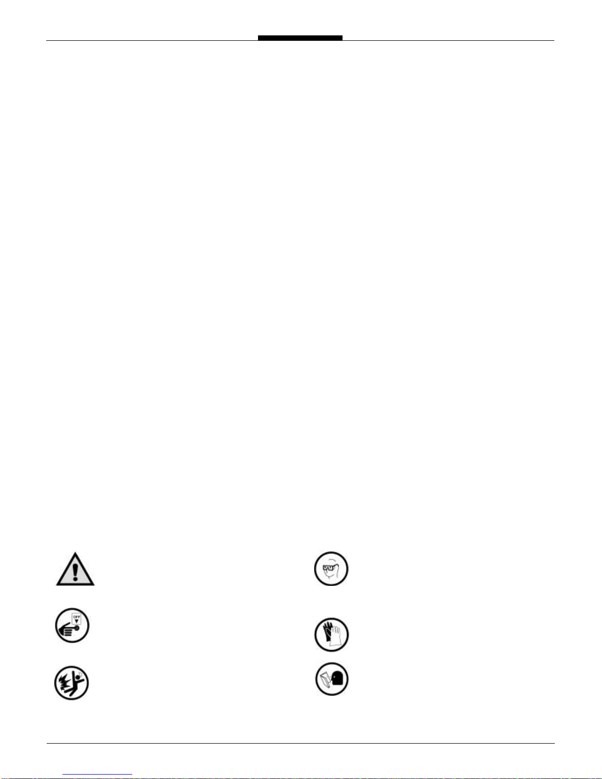
CAUTION
Follow the warning instructions within the fol-
lowing information to avoid equipment failure,
personal injury or death.
TURN POWER OFF
Before performing any maintenance, be sure to
turn system power off to avoid any potential
electric spark
FLAMMABLE
Flammable liquids and their vapors may cause a
fire or explosion if ignited.
EYE PROTECTION
Pressurized systems may cause hazardous leaks
and spray that may be dangerous for your eyes.
Always wear eye protection around pressurized
systems and its hazardous liquids.
INJURY
Wear gloves for protection from hazardous liq-
uids that may cause irritation or burns.
READ
Read and understand all related manuals thor-
oughly. The Engineering and OIM manuals will
provide the knowledge for all systems, mainte-
nance and operation procedures. If you have any
questions, please consult the factory.
Safety Warning Symbols 2
Receipt & Inspection
3
Notice 3
Meter Overview 4
Meter Specifications
5
Meter Types
5
Material of Construction
6
System Recommendations
6
System Recommendations (Continued)
7
System Recommendations (Continued)
8
Above Ground Storage System
9
Mobile Fueling System
10
Start Up Recommendations 11
Start Up Recommendations (Continued) 12
Direction of Flow 12
Meter Calibration
13
Meter Calibration (Continued)
14
Meter Calibration (Continued) 15
Calibration Adjustment 15
Split Compartment Testing 16
Split Compartment Testing (Continued) 17
Split Compartment Testing (Continued) 18
Maintenance 19
Maintenance (Continued) 20
Storage Instructions 20
Dimensions 21
Meter Assembly 22
Meter Assembly (Continued) 23
Air Eliminator Assembly 24
Air Eliminator Assembly (Continued) 25
Strainer Assembly 26
High Volume Strainer Assembly 27
Hydraulic Preset Valve Assembly
28
Hydraulic Preset Valve Assembly (Continued)
29
Air Check Valve Assembly 30
Back Pressure Check Valve Assembly 31
Torque Specifications
32
Drive Components 33
Disassembly of Meter 34
Disassembly of Meter (Continued) 35
Disassembly of Meter (Continued) 36
Inspection of Parts 37
Reassembly of Meter 38
Reassembly of Meter (Continued) 39
Reassembly of Meter (Continued) 40
Reassembly of Meter (Continued) 41
Disassembly of Strainer 42
Reassembly of Strainer 42
Disassembly of Air Eliminator 43
Reassembly of Air Eliminator 43
Disassembly of Hydraulic Preset Valve 44
Disassembly of Hydraulic Preset Valve (Continued) 45
Reassembly of Hydraulic Preset Valve 45
Disassembly of Air Check Valve 46
Reassembly of Air Check Valve 46
Meter Trouble Shooting 47
Air Eliminator Trouble Shooting 48
Hydraulic Preset Valve Trouble Shooting 49
Air Check Valve Trouble Shooting 49
Material Safety Data Sheet 50
MSDS (Continued) 51
MSDS (Continued) 52
MSDS (Continued) 53
Notes 54
Warranty 55