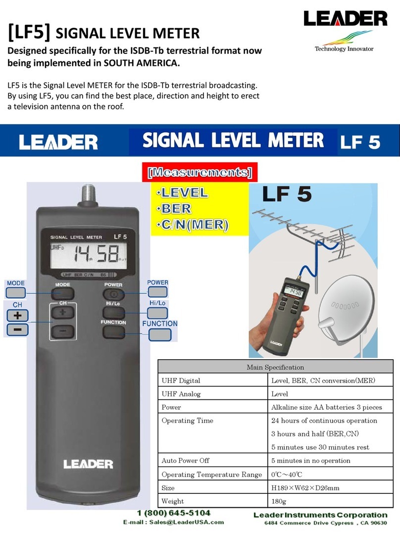
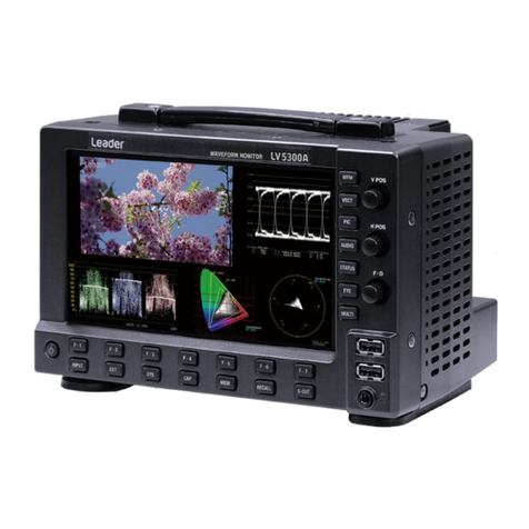
Leader LV 5480 Parts list manual

LV 5490SER01 SDI INPUT
LV 5490SER02 SDI INPUT / EYE
LV 5490SER03 DIGITAL AUDIO Dolby (Option)
LV 5490SER04 FOCUS ASSIST
LV 5490SER05 CIE DIAGRAM
LV 5490SER06 12G-SDI INPUT
LV 5490SER07 HDR
LV 5490SER08 IP (NMI)
LV 5490SER09 12G-SDI EYE
LV 5490SER10 VIDEO NOISE METER
FUNCTION MENU EXPLANATIONS
Thank you for purchasing.
Please carefully read this instruction manual and the included "GENERAL SAFETY SUMMARY".
Please use the product safely.

TABLE OF CONTENTS
1. INTRODUCTION ........................................................................................................ 1
1.1 About This Manual.....................................................................................................................1
1.2 About Trademarks and Licenses...............................................................................................1
1.3 About Terminology Used in this Manual....................................................................................1
1.4 About the LV 5480 .....................................................................................................................3
2. VIDEO SIGNAL WAVEFORM DISPLAY..................................................................... 4
2.1 Setting the Waveform Display Position .....................................................................................4
2.2 Configuring the Display Settings ...............................................................................................5
2.2.1 Adjusting the Vector Intensity.............................................................................................5
2.2.2 Selecting the Vector Color .................................................................................................5
2.2.3 Adjusting the Scale Intensity..............................................................................................6
2.2.4 Selecting the Scale Color...................................................................................................6
2.2.5 Selecting the Scale Unit.....................................................................................................6
2.2.6 Displaying a Scale for 75 % Intensity Color Bars ..............................................................9
2.2.7 Selecting the Display Mode .............................................................................................10
2.2.8 Turning the Channels On and Off .................................................................................... 11
2.2.9 4Y Parade Display............................................................................................................ 11
2.2.10 Configuring the 3G-B-DS Display Settings......................................................................12
2.3 Configuring the Gain and Filter Settings .................................................................................13
2.3.1 Selecting the Fixed Gain..................................................................................................13
2.3.2 Setting the Variable Gain .................................................................................................13
2.3.3 Selecting the Filter ...........................................................................................................14
2.3.4 Setting the Scale Jump ....................................................................................................16
2.4 Configuring Sweep Settings....................................................................................................18
2.4.1 Selecting the Sweep Method ...........................................................................................18
2.4.2 Selecting the Line Display Format ...................................................................................19
2.4.3 Selecting the Field Display Format ..................................................................................20
2.4.4 Selecting the Horizontal Magnification.............................................................................21
2.4.5 Displaying the Blanking Interval.......................................................................................23
2.5 Configuring Line Selection Settings ........................................................................................24
2.5.1 Turning Line Selection On and Off...................................................................................24
2.5.2 Setting the Line Selection Range.....................................................................................25
2.6 Configuring Cursor Settings ....................................................................................................25
2.6.1 Turning Cursors On and Off.............................................................................................25
2.6.2 Selecting the Cursor.........................................................................................................26
2.6.3Moving Cursors ................................................................................................................26
2.6.4 Selecting the Y-Axis Measurement Unit...........................................................................27
2.6.5 Selecting the X-Axis Measurement Unit ..........................................................................27
2.6.6 Turning the Cursor Value Display On and Off..................................................................28
2.7 Configuring the Color System Settings ...................................................................................29
2.7.1 Selecting the Color Matrix................................................................................................29
2.7.2 Turning the Luminance Signal On and Off.......................................................................31
2.7.3 Selecting the Composite Display Format.........................................................................32

2.7.4 Selecting the Setup Level ................................................................................................32
3. VECTOR WAVEFORM DISPLAY ............................................................................. 33
3.1 Configuring the Intensity and Scale Settings ..........................................................................34
3.1.1 Adjusting the Vector Intensity...........................................................................................34
3.1.2 Selecting the Vector Color ...............................................................................................34
3.1.3 Adjusting the Scale Intensity............................................................................................34
3.1.4 Selecting the Scale Color.................................................................................................35
3.1.5 Turning the Display of the I and Q Axes On and Off........................................................35
3.1.6 Selecting the Scale ..........................................................................................................36
3.2 Setting the Gain.......................................................................................................................36
3.2.1 Selecting the Fixed Gain ..................................................................................................37
3.2.2 Setting the Variable Gain .................................................................................................37
3.3 Configuring Line Selection Settings ........................................................................................38
3.3.1 Turning Line Selection On and Off...................................................................................38
3.3.2 Setting the Line Selection Range.....................................................................................39
3.4 Configuring Marker Settings....................................................................................................40
3.4.1 Displaying the Vector Marker ...........................................................................................40
3.5 Configuring the Display Settings .............................................................................................41
3.5.1 Switching the Display Mode.............................................................................................41
3.5.2 Configuring the 3G-B-DS Display Settings......................................................................41
3.6 Configuring the Color System Settings ...................................................................................42
3.6.1 Selecting the Color Matrix................................................................................................43
3.6.2 Selecting the Composite Display Format.........................................................................44
3.6.3 Selecting the Setup Level ................................................................................................45
3.6.4 Displaying a Scale for 75 % Intensity Color Bars ............................................................45
3.7 5-Bar Display ...........................................................................................................................46
3.7.1 Selecting the Scale Unit...................................................................................................47
3.7.2 Selecting the Display Order .............................................................................................47
3.8 Histogram Display ...................................................................................................................48
4. CIE DIAGRAM DISPLAY (SER05) ........................................................................... 49
4.1 Configuring the Scale Settings................................................................................................50
4.1.1 Selecting the Triangle.......................................................................................................50
4.1.2 Setting the User-defined Triangle ....................................................................................51
4.1.3 Selecting the Color Scale.................................................................................................52
4.1.4 Turning the Sub Scale On and Off...................................................................................53
4.2 Setting the Chromaticity Diagram Mode .................................................................................54
4.2.1 Selecting the Display Type...............................................................................................54
4.2.2 Selecting the Display Standard ........................................................................................55
4.2.3 Turning Clipping On and Off ............................................................................................55
4.2.4 Turning the Filter On and Off ...........................................................................................55
4.2.5 Setting the Gamma Value ................................................................................................55
4.3 Configuring Line Selection Settings ........................................................................................56
4.4 Configuring Cursor Settings ....................................................................................................56
4.4.1 Displaying the Chromaticity Diagram Cursor...................................................................56

4.5 Configuring the Display Settings .............................................................................................56
5. PICTURE DISPLAY.................................................................................................. 57
5.1 Adjusting the Picture ...............................................................................................................57
5.1.1 Switching between the Color and Monochrome Displays ...............................................57
5.1.2 Setting the Chroma Gain..................................................................................................57
5.1.3 Adjusting the Brightness ..................................................................................................58
5.1.4 Adjusting the Contrast......................................................................................................58
5.1.5 Adjusting the Gain............................................................................................................58
5.1.6 Adjusting the Bias ............................................................................................................59
5.2 Configuring Marker Settings....................................................................................................59
5.2.1 Turning the Display of the Frame Marker On and Off......................................................60
5.2.2 Turning the Display of the Center Marker On and Off .....................................................60
5.2.3 Setting the Aspect Marker................................................................................................60
5.2.4 Setting the Aspect Shadow ..............................................................................................62
5.2.5 Setting the Safe Action Marker ........................................................................................63
5.2.6 Setting the Safe Title Marker............................................................................................63
5.2.7 Setting User Markers .......................................................................................................64
5.3 Configuring Line Selection Settings ........................................................................................64
5.3.1 Turning Line Selection On and Off...................................................................................65
5.3.2 Setting the Line Selection Range.....................................................................................65
5.3.3 Setting the Lip Sync Measurement Range (SER03) .......................................................66
5.4 Configuring CINELITE Settings...............................................................................................67
5.4.1 f Stop Screen Explanation................................................................................................68
5.4.2 Procedure for Displaying the f Stop Screen.....................................................................69
5.4.3 %DISPLAY Screen Explanation.......................................................................................70
5.4.4 Selecting the Points to Display ........................................................................................73
5.4.5 Setting Measurement Points............................................................................................73
5.4.6 Setting the Area of Luminance Measurement .................................................................73
5.4.7 Configuring User-Defined Correction Tables ...................................................................74
5.4.8 Displaying Synchronized Markers....................................................................................79
5.5 Configuring CINEZONE Settings ............................................................................................80
5.5.1 Gradation Display Mode...................................................................................................80
5.5.2 Step Display Mode ...........................................................................................................80
5.5.3 Search Display Mode.......................................................................................................81
5.6 Focus Assist Display (SER04) ................................................................................................82
5.6.1 Selecting the Display Size ...............................................................................................82
5.6.2 Turning Focus Assist On and Off .....................................................................................82
5.6.3 Selecting the Detection Sensitivity...................................................................................82
5.6.4 Selecting the Luminance Level........................................................................................83
5.6.5 Selecting the Highlight Color............................................................................................83
5.7 Video Noise Meter (SER10) ....................................................................................................84
5.7.1 Turning Video Noise Meter On and Off............................................................................84
5.7.2 Configuring the Measurement Window............................................................................85
5.7.3 Selecting the Signal to Measure ......................................................................................86
5.7.4 Selecting the Filter ...........................................................................................................86
5.7.5 Selecting the Measurement Result Display Size.............................................................86

5.7.6 Turning the Alarm Function On and Off ...........................................................................87
5.7.7 Setting the Threshold of the Alarm Function....................................................................87
5.8 Configuring the Display Settings .............................................................................................88
5.8.1 Selecting the Display Size ...............................................................................................88
5.8.2 Gamut Error Display.........................................................................................................89
5.8.3 Turning the Information On and Off .................................................................................89
5.8.4 Configuring the 3G-B-DS Display Settings......................................................................91
6. HDR DISPLAY (SER07) ........................................................................................... 92
6.1 Video Signal Waveform Display ..............................................................................................94
6.1.1 Scale Display....................................................................................................................94
6.1.2 Cursor Display..................................................................................................................96
6.2 Vector Waveform Display ........................................................................................................97
6.2.1 Histogram Display ............................................................................................................97
6.3 Picture Display.........................................................................................................................98
6.3.1 Turning Brightness Information On and Off .....................................................................98
6.3.2 Selecting the SDR Conversion Format............................................................................99
6.3.3 f Stop Screen..................................................................................................................100
6.3.4 %DISPLAY Screen.........................................................................................................101
6.3.5 CINEZONE Display........................................................................................................102
7. AUDIO DISPLAY .................................................................................................... 104
7.1 Setting the Signals to Measure .............................................................................................106
7.2 Configuring the Dolby Settings (option) ................................................................................109
7.3 Selecting the Display Mode................................................................................................... 110
7.4 Configuring Error Detection Settings.....................................................................................112
7.5 Adjusting the Volume............................................................................................................. 112
7.6 Meter Display.........................................................................................................................113
7.6.1 Selecting the Scale ........................................................................................................113
7.6.2 Selecting the Response Model ...................................................................................... 113
7.6.3 Setting the Peak Hold ....................................................................................................114
7.6.4 Setting the Reference Level........................................................................................... 114
7.7 Lissajous Display...................................................................................................................115
7.7.1 Adjusting the Lissajous Curve Intensity ......................................................................... 115
7.7.2 Adjusting the Scale Intensity.......................................................................................... 115
7.7.3 Selecting the Lissajous Curve Display Format .............................................................. 116
7.7.4 Selecting the Scale Display Format............................................................................... 117
7.7.5 Setting the Lissajous Curve Gain................................................................................... 118
7.8 Surround Display...................................................................................................................119
7.8.1 Adjusting the Surround Waveform Intensity .................................................................. 119
7.8.2 Adjusting the Scale Intensity.......................................................................................... 119
7.8.3 Selecting the Surround Display Format .........................................................................120
7.8.4 Setting the Surround Waveform Gain............................................................................120
7.9 Status Display........................................................................................................................121
7.9.1 Status Display Explanation ............................................................................................121
7.9.2 Event Log Display ..........................................................................................................123

7.9.3 Metadata Display (Option) .............................................................................................124
7.9.4 Displaying the Channel Status .......................................................................................127
7.9.5 Displaying User Bits .......................................................................................................128
7.9.6 Resetting Errors .............................................................................................................128
8. STATUS DISPLAY .................................................................................................. 129
8.1 Status Screen Explanation ....................................................................................................129
8.2 Configuring Error Detection Settings.....................................................................................133
8.2.1 Error Setup 1 ..................................................................................................................133
8.2.2 Error Setup 2 ..................................................................................................................136
8.2.3 Error Setup 3 ..................................................................................................................137
8.2.4 Error Setup 4 ..................................................................................................................140
8.3 Clearing Error Counts............................................................................................................143
8.4 Configuring Event Log Settings.............................................................................................143
8.4.1 Event Log Screen Explanation.......................................................................................144
8.4.2 Starting the Event Log....................................................................................................148
8.4.3 Deleting the Event Log...................................................................................................148
8.4.4 Selecting the Overwrite Mode........................................................................................148
8.4.5 Saving to USB Memory..................................................................................................149
8.5 Configuring Data Dump Settings...........................................................................................151
8.5.1 Data Dump Display Explanation ....................................................................................152
8.5.2 Selecting the Display Mode ...........................................................................................154
8.5.3 Selecting the Display Format.........................................................................................154
8.5.4 Selecting the Displayed Information ..............................................................................156
8.5.5 Moving the Display Position...........................................................................................156
8.5.6 Selecting the Adjustment Step Resolution .....................................................................156
8.5.7 Selecting What the Function Dial Controls ....................................................................157
8.5.8 Saving to USB Memory..................................................................................................157
8.6 Configuring Phase Difference Measurement Settings..........................................................158
8.6.1 Phase Difference Measurement Display Explanation ...................................................159
8.7 Setting the Lip Sync Measurement (SER03) ........................................................................163
8.7.1 Selecting the Measurement Range................................................................................164
8.7.2 Updating the Measurement Screen...............................................................................164
8.7.3 Setting the Measurement Range ...................................................................................165
8.8 Displaying a List of Ancillary Data .........................................................................................168
8.8.1 Ancillary Data Display Explanation ................................................................................168
8.8.2 Displaying a Dump of Ancillary Data..............................................................................169
8.8.3 Updating the Dump Display ...........................................................................................169
8.8.4 Selecting the Dump Mode..............................................................................................170
8.9 Detecting Ancillary Packets ...................................................................................................171
8.9.1 Ancillary Packet Display Explanation.............................................................................171
8.9.2 Displaying EDH Packets ................................................................................................173
8.9.3 Displaying Payload IDs ..................................................................................................174
8.9.4 Displaying Audio Control Packets ..................................................................................175
8.9.5 V-ANC ARIB Display ......................................................................................................176
8.9.6 Displaying Closed Caption Packets...............................................................................176
8.9.7 Displaying the Inter-Stationary Control Signal ...............................................................177

8.9.8 Displaying the Data Broadcast Trigger Signal ...............................................................180
8.9.9 Displaying User Data .....................................................................................................181
8.9.10 V-ANC SMPTE Display..................................................................................................181
8.9.11 Displaying AFD Packets.................................................................................................182
8.9.12 Performing Custom Searches........................................................................................183
8.10 IP(NMI) Status Screen Explanation (SER08)........................................................................185
9. EYE PATTERN DISPLAY (SER02/SER09) ............................................................ 187
9.1 Eye Pattern Display Explanation...........................................................................................188
9.2 Jitter Display Explanation ......................................................................................................190
9.3 Setting the Waveform Display Position .................................................................................191
9.4 Switching between Eye Pattern and Jitter ............................................................................191
9.5 Selecting Which Link to Display ............................................................................................191
9.6 Configuring the Intensity and Scale Settings ........................................................................192
9.6.1 Adjusting the Waveform Intensity ..................................................................................192
9.6.2 Selecting the Waveform Color .......................................................................................192
9.6.3 Adjusting the Scale Intensity..........................................................................................192
9.6.4 Selecting the Scale Color...............................................................................................192
9.7 Configuring Eye Pattern Display Settings .............................................................................193
9.7.1 Adjusting the Gain..........................................................................................................193
9.7.2 Selecting the Sweep Time .............................................................................................193
9.7.3 Selecting the Filter .........................................................................................................195
9.7.4 Turning Cursors On and Off...........................................................................................196
9.7.5 Selecting the Cursor.......................................................................................................197
9.7.6 Moving Cursors ..............................................................................................................199
9.7.7 Selecting the X-Axis Measurement Unit ........................................................................199
9.7.8 Selecting the Y-Axis Measurement Unit.........................................................................200
9.7.9 Selecting the Display Mode ...........................................................................................200
9.7.10 Resetting Cursors ..........................................................................................................200
9.8 Configuring the Jitter Display Settings ..................................................................................201
9.8.1 Selecting the Magnification ............................................................................................201
9.8.2 Selecting the Sweep Time .............................................................................................201
9.8.3 Selecting the Filter .........................................................................................................202
9.8.4 Turning Cursors On and Off...........................................................................................202
9.8.5 Selecting the Cursor.......................................................................................................203
9.8.6 Moving Cursors ..............................................................................................................203
9.8.7 Selecting the X-Axis Measurement Unit ........................................................................204
9.8.8 Selecting the Y-Axis Measurement Unit.........................................................................204
9.8.9 Selecting the Display Mode ...........................................................................................204
9.8.10 Resetting Cursors ..........................................................................................................204
9.8.11 Turning the Peak Hold On and Off.................................................................................205
9.8.12 Clearing the Peak Hold ..................................................................................................205
9.9 Configuring Error Detection Settings.....................................................................................206
9.9.1 Configuring 12G Error Settings......................................................................................206
9.9.2 Configuring 3G Error Settings........................................................................................208
9.9.3 Configuring HD Error Settings .......................................................................................210
9.9.4 Configuring SD Error Settings........................................................................................212

10. Installing the Plug-in (SER08)................................................................................. 214
11. MENU TREE .......................................................................................................... 218
11.1 WFM Menu ............................................................................................................................218
11.2 VECT Menu ...........................................................................................................................220
11.3 PIC Menu...............................................................................................................................223
11.4 AUDIO Menu (SER03) ..........................................................................................................226
11.5 STATUS Menu .......................................................................................................................228
11.6 EYE Menu (SER02/SER09) ..................................................................................................232

1. INTRODUCTION
1
1. INTRODUCTION
1.1 About This Manual
This manual explains the measurement menus that become available when any of the
following units or option is installed in the LV 5490 (MULTI WAVEFORM MONITOR).
For the product specifications and details on how to operate the LV 5490, see the LV 5490
Instruction Manual.
・LV 5490SER01 (SDI INPUT), LV 5490SER02 (SDI INPUT / EYE), LV 5490SER06
(12G-SDI INPUT), or LV 5490SER08 (IP(NMI))
・LV 5490SER03 (DIGITAL AUDIO)
・LV 5490SER04 (FOCUS ASSIST)
・LV 5490SER05 (CIE DIAGRAM)
・LV 5490SER07 (HDR)
・LV 5490SER09 (12G-SDI EYE)
・Dolby option
1.2 About Trademarks and Licenses
The company and product names in this document are trademarks or registered trademarks of
their respective holders.
1.3 About Terminology Used in this Manual
●SER**
LV 5490SER** is referred to as SER**.
●Single Input Mode
This refers to the mode in which on the INPUT menu, F•7 DISPLAY is set to SINGLE.
It is a mode for measuring a single input signal.
●Simul Mode
This refers to the mode in which on the INPUT menu, F•7 DISPLAY is set to SIMUL.
It is a mode for measuring multiple input signals simultaneously.
●Multi Display
This refers to the mode in which the MULTI key is on.
●About Underlining (_)
Underlined options indicate the default values.

1. INTRODUCTION
2
●Input Formats and Link Systems
The following names are used for the input formats and link systems.
Multi link may be used as a collective term to refer to dual link and quad link.
Table 1-1 Input formats and link systems
Name Description Link System
SD SD-SDI Single link
HD HD-SDI Single link
3G-A 3G-SDI level A Single link
3G-B-DL 3G-SDI level B dual link mapping Single link
3G-B-DS 3G-SDI level B dual stream mapping Single link
12G 12G-SDI TYPE1 Single link
HD (DL) HD-SDI dual link Dual link
HD (QL) HD-SDI quad link Quad link
3G (DL)-2K 3G-A, 3G-B-DL dual link
Resolution 1920(2048)×1080
Dual Link
3G (DL)-4K 3G-B-DS dual link
Resolution 3840(4096)×2160
Dual Link
3G (QL) 3G-A, 3G-B-DL quad link Quad link
3G Collective name for 3G links -
3G-B Collective name for 3G-B-DL and 3G-B-DS -
3G (DL) Collective name for 3G (DL)-2K and 3G (DL)-4K -
4K Collective name for HD (QL), 3G (DL)-4K, 3G (QL) and 12G -

1. INTRODUCTION
3
1.4 About the LV 5480
This manual explains the LV 5490.
If you are using the LV 5480, refer to the LV 5490 vs. LV 5480 comparison table below, and
read LV 5490 as LV 5480 in this manual.
Table 1-2 LV 5490 vs. LV 5480 comparison
Item LV 5490 LV 5480
Supported units LV 5490SER01
LV 5490SER02
LV 5490SER03
LV 5490SER06
LV 5490SER08
LV 5490SER01
LV 5490SER02
LV 5490SER03
LV 5490SER06 (*1)
LV 5490SER08 (*1)
Supported options LV 5490SER04
LV 5490SER05
LV 5490SER07
LV 5490SER09 (*2)
LV 5490SER04
LV 5490SER05
LV 5490SER07
LV 5490SER09 (*2)
LV 5480SER20
LV 5480SER21
4K function Standard support Supported with LV 5480SER20 (*3)
Signal generation function Standard support Supported with LV 5480SER21 (*4)
USB save destination folder name LV5490_USER LV5480_USER
TELNET login and password LV5490 LV5480
FTP login and password LV5490 LV5480
SNMP MIB file name lv5490.my lv5490.my (*5)
*1 The LV 5480SER20 must be installed to install the LV 5490SER06 or LV 5490SER08.
*2 The LV 5490SER06 must be installed, to install LV 5490SER09.
*3 Installing the LV 5480SER20 enables you to select 4K 3G Quad Link, 4K 3G Dual Link, and 4K HD Quad
Link for SDI System on the SDI IN tab.
*4 Installing the LV 5480SER21 enables you to select Test Signal for Mode on the SDI OUT tab.
*5 The MIB file is shared with the LV 5490, but the SNMP manager detects it as “LV5480.”The other
aspects of the SNMP function are the same as those of the LV 5490.

2. VIDEO SIGNAL WAVEFORM DISPLAY
4
2. VIDEO SIGNAL WAVEFORM DISPLAY
To display the video signal waveform, press WFM.
Figure 2-1 Video signal waveform display
●Colorimetry
Normally, colorimetry is not displayed, but when the colorimetry alarm is set to on in the system
settings and a colorimetry different from the one specified is received, the alarm is indicated in
red in the upper left of the screen.
2.1 Setting the Waveform Display Position
Use the V POS and H POS knobs to adjust the display position of video signal waveforms.
On the multi display, these are valid when you press F•2 MULTI WFM on the MULTI menu.
Figure 2-2 V POS and H POS knobs
●V POS Knob
This knob adjusts the vertical position of the video signal waveform.
Pressing the knob returns the waveform to its default position.
●H POS Knob
This knob adjusts the horizontal position of the video signal waveform.
Pressing the knob returns the waveform to its default position.

2. VIDEO SIGNAL WAVEFORM DISPLAY
5
2.2 Configuring the Display Settings
To configure the display settings, press F•1 INTEN/SCALE/DISPLAY on the WFM menu.
WFM → F•1 INTEN/SCALE/DISPLAY →
Figure 2-3 INTEN/SCALE/DISPLAY menu
2.2.1 Adjusting the Vector Intensity
To adjust the video signal waveform intensity, follow the procedure below.
Press the function dial (F•D) to return the setting to its default value (0).
Procedure
WFM → F•1 INTEN/SCALE/DISPLAY → F•1 WFM INTEN: -128 - 0 - 127
2.2.2 Selecting the Vector Color
To select the video signal waveform color, follow the procedure below.
On the multi display, the following colors are assigned to the video signal waveforms.
Y: white, Cb: cyan, Cr: magenta
G: green, B: blue, R: red
X: white, Y: white, Z: white
COMPOSIT: white
Procedure (when not measuring 3G-B-DS)
WFM → F•1 INTEN/SCALE/DISPLAY → F•2 WFM COLOR: WHITE / YELLOW / CYAN /
GREEN / MAGENTA / RED / BLUE / MULTI
Procedure (when measuring 3G-B-DS)
WFM → F•1 INTEN/SCALE/DISPLAY → F•2 WFM COLOR
→ F•1 STREAM1 COLOR: WHITE / YELLOW / CYAN / GREEN / MAGENTA / RED / BLUE /
MULTI
→ F•2 STREAM2 COLOR: WHITE / YELLOW / CYAN / GREEN / MAGENTA / RED / BLUE /
MULTI

2. VIDEO SIGNAL WAVEFORM DISPLAY
6
2.2.3 Adjusting the Scale Intensity
To configure the scale, press F•3 WFM SCALE on the INTEN/SCALE/DISPLAY menu.
WFM → F•1 INTEN/SCALE/DISPLAY → F•3 WFM SCALE →
Figure 2-4 WFM SCALE menu
To adjust the scale intensity, follow the procedure below.
Press the function dial (F•D) to return the setting to its default value (4).
Procedure
WFM → F•1 INTEN/SCALE/DISPLAY → F•3 WFM SCALE → F•1 SCALE INTEN: -8 - 4 - 7
2.2.4 Selecting the Scale Color
To select the scale color, follow the procedure below.
Procedure
WFM → F•1 INTEN/SCALE/DISPLAY → F•3 WFM SCALE → F•2 SCALE COLOR: WHITE
/ YELLOW / CYAN / GREEN / MAGENTA / RED / BLUE
2.2.5 Selecting the Scale Unit
To select the scale unit, follow the procedure below.
When COLOR MATRIX is set to XYZ, the scale unit is set to “HD%,SD%” or 150%.
When COLOR MATRIX is set to COMPOSIT and the composite display format is NTSC, this
is fixed to HD%,SD%. When the composite display format is PAL, this is fixed to HDV,SDV.
Video signal white (100 %) becomes 0.7 V or 100 % on the scale.
Video signal black (0 %) becomes 0 V or 0 % on the scale.
Reference COLOR MATRIX → section 2.7.1, “Selecting the Color Matrix.”
Procedure
WFM → F•1 INTEN/SCALE/DISPLAY → F•3 WFM SCALE → F•3 SCALE UNIT: HDV,SD%
/ HDV,SDV / HD%,SD% / 150% / 1023 / 1023,255 / 3FF
Settings
HDV,SD%: The scale shows voltages when the input signal is not SD and percentages
when the input signal is SD.
HDV,SDV: The scale shows voltages.
HD%,SD%: The scale shows percentages.
150%: The scale shows percentages. (The scale starts from -50 %.)
1023: 0 to 100 % is displayed as 64 to 940 (YGBR) or 64 to 960 (CbCr).
1023,255: 0 to 100 % is displayed as 64 to 940 (YGBR) or 16 to 235 (YGBR).
3FF: 0 to 100 % is displayed as 040 to 3AC (YGBR) or 040 to 3C0 (CbCr).

2. VIDEO SIGNAL WAVEFORM DISPLAY
7
SCALE UNIT = HDV,SDV
SCALE UNIT = HD%,SD%
SCALE UNIT = 150%

2. VIDEO SIGNAL WAVEFORM DISPLAY
8
SCALE UNIT = 1023
SCALE UNIT = 1023,255
SCALE UNIT = 3FF
Figure 2-5 Selecting the scale unit

2. VIDEO SIGNAL WAVEFORM DISPLAY
9
2.2.6 Displaying a Scale for 75 % Intensity Color Bars
When COLOR MATRIX is set to YCbCr, to display a scale that matches the peak levels of
the color difference signals for 75 % intensity color bars, follow the procedure below.
Reference COLOR MATRIX → section 2.7.1, “Selecting the Color Matrix.”
Procedure
WFM → F•1 INTEN/SCALE/DISPLAY → F•3 WFM SCALE → F•4 75%COLOR SCALE: ON
/ OFF
75%COLOR SCALE = ON
Figure 2-6 Displaying a scale for 75 % intensity color bars

2. VIDEO SIGNAL WAVEFORM DISPLAY
10
2.2.7 Selecting the Display Mode
To configure the display, press F•4 WFM DISPLAY on the INTEN/SCALE/DISPLAY menu.
WFM → F•1 INTEN/SCALE/DISPLAY → F•4 WFM DISPLAY →
Figure 2-7 WFM DISPLAY menu
To select the video signal waveform display mode, follow the procedure below.
This setting is invalid when COLOR MATRIX is set to COMPOSIT.
Reference COLOR MATRIX → section 2.7.1, “Selecting the Color Matrix.”
Procedure
WFM → F•1 INTEN/SCALE/DISPLAY → F•4 WFM DISPLAY → F•1 WFM MODE:
OVERLAY / PARADE
Settings
OVERLAY: Input signal is displayed on top of each other.
PARADE: Input signal is displayed side by side.
WFM MODE = OVERLAY
WFM MODE = PARADE
Figure 2-8 Selecting the display mode

2. VIDEO SIGNAL WAVEFORM DISPLAY
11
2.2.8 Turning the Channels On and Off
To turn individual channels on and off, follow the procedure below.
You cannot turn off all the channels.
This menu item is not available when COLOR MATRIX is set to COMPOSIT or when YGBR
or YRGB is set to ON.
Reference COLOR MATRIX → section 2.7.1, “Selecting the Color Matrix.”
YGBR, YRGB → section 2.7.2, “Turning Luminance Signals On and Off.”
Procedure
WFM → F•1 INTEN/SCALE/DISPLAY → F•4 WFM DISPLAY
→ F•2 CH1 Y / CH1 X / CH1 G / CH1 R: ON / OFF
→ F•3 CH2 Cb / CH2 Y / CH2 B / CH2 G: ON / OFF
→ F•4 CH3 Cr / CH3 Z / CH3 R / CH3 B: ON / OFF
2.2.9 4Y Parade Display
To extract the Y signals from channels A to D and display them side by side, follow the
procedure below.
The conditions for displaying the 4Y parade display are listed below.
• Single link
• Simul mode
• F•7 COLOR SYSTEM → F•1 COLOR MATRIX on the WFM menu is set to YCbCr or
COMPOSIT.
• F•6 OPERATE CH MODE on the INPUT menu is set to COM.
• The layout display mode is set to NORMAL.
Also, note the following points.
• Only the channels that have been set to ON on the INPUT menu are displayed.
• Option in layout will be hidden.
• Style in layout will be invalid.
• The scale jump function cannot be used.
Procedure
WFM → F•1 INTEN/SCALE/DISPLAY → F•4 WFM DISPLAY → F•5 4Y PARADE: ON / OFF
4Y PARADE = OFF

2. VIDEO SIGNAL WAVEFORM DISPLAY
12
4Y PARADE = ON
Figure 2-9 4Y parade display
2.2.10 Configuring the 3G-B-DS Display Settings
When measuring 3G-B-DS, to select the display mode, follow the procedure below.
Procedure
WFM → F•1 INTEN/SCALE/DISPLAY → F•4 WFM DISPLAY → F•5 3G-B-DS DISPLAY:
STREAM1 / STREAM2 / MIX / ALIGN
Settings
STREAM1: Stream 1 is displayed.
STREAM2: Stream 2 is displayed.
MIX: Streams 1 and 2 are displayed on top of each other.
ALIGN: Streams 1 and 2 are displayed side by side.
3G-B-DS DISPLAY = MIX
This manual suits for next models
11
Table of contents
Other Leader Measuring Instrument manuals

Leader
Leader PHABRIX Rx 2000 User manual

Leader
Leader LV5300 User manual

Leader
Leader V90.90.049 User manual

Leader
Leader LE 8682 User manual

Leader
Leader D11.06.010 User manual

Leader
Leader Search User manual

Leader
Leader LV 7380 User manual

Leader
Leader LV 7770 User manual

Leader
Leader LV5300 User manual

Leader
Leader LV5300 Installation guide
Popular Measuring Instrument manuals by other brands

CAMET
CAMET CAA-500 instruction manual

EXFO
EXFO FTB-2 Pro user guide

JENCO
JENCO VisionPlus EC 330 Operation manual

Keysight
Keysight 16192A Operation and service manual

Decagon Devices
Decagon Devices AquaLab 4TE Installation Qualification/Operational Qualification Protocols and Instructions

Amprobe
Amprobe ACD-30P user manual