manuals.online logo
Brands
  1. Home
  2. •
  3. Brands
  4. •
  5. TDK
  6. •
  7. Computer Hardware
  8. •
  9. TDK FReta Series User manual

TDK FReta Series User manual

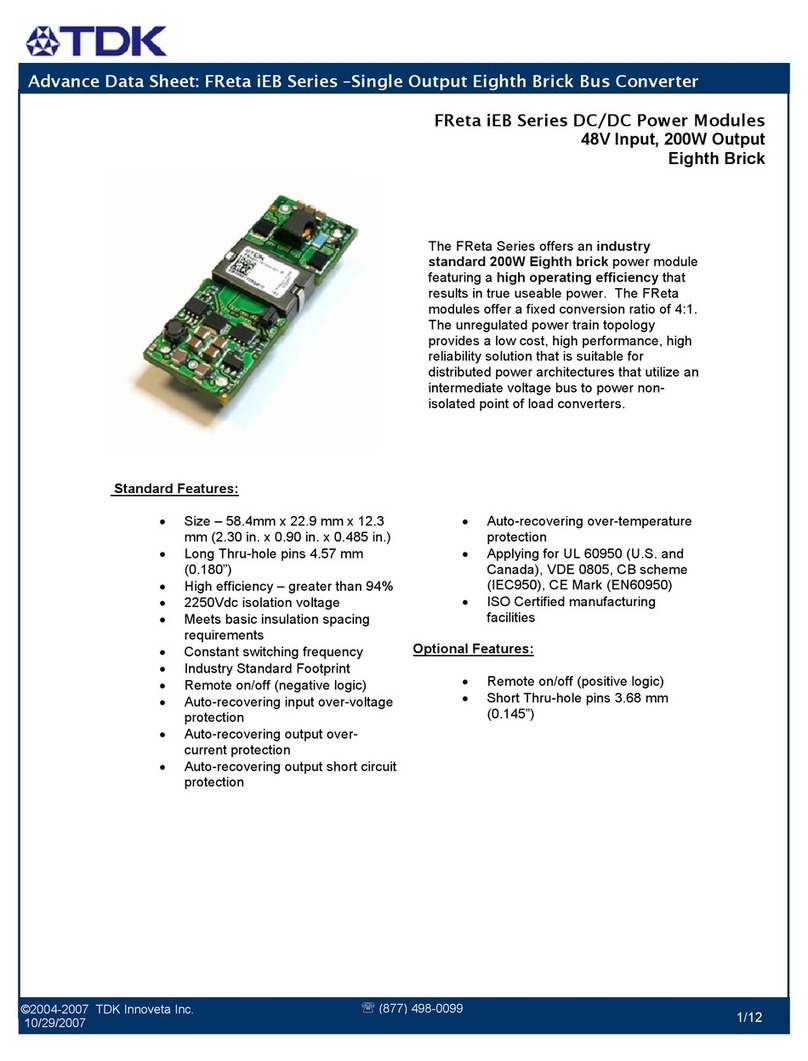
Data Sheet: FReta iEB Series –Single Output Eighth Brick Bus Converter
©2004-2006 TDK Innoveta Inc.
1/24/2008
℡
(877) 498
-
0099
1/13
The FReta Se ies offe s an industry
standard 150W Eighth brick powe module
featu ing a high operating efficiency that
esults in t ue useable powe . The FReta
modules offe a fixed conve sion atio of
eithe 4:1 o 5:1.
Standard Features:
• Size – 58.4mm x 22.9 mm x 8.5
mm (2.30 in. x 0.90 in. x 0.34 in.)
• Th u-hole pins 3.68 mm (0.145”)
• High efficiency – g eate than 94%
• 2250Vdc isolation voltage
• Meets basic insulation spacing
equi ements
• Constant switching f equency
• Indust y Standa d Footp int
• Remote on/off (positive logic)
• Auto- ecove ing input ove -voltage
p otection
• Auto- ecove ing output ove -
cu ent p otection
• Auto- ecove ing output sho t ci cuit
p otection
• Auto- ecove ing ove -tempe atu e
p otection
• Applying fo UL 60950 (U.S. and
Canada), VDE 0805, CB scheme
(IEC950), CE Ma k (EN60950)
• ISO Ce tified manufactu ing
facilities
Optional Features:
• Remote on/off (negative logic)
• Sho t Th u-hole pins 2.79 mm
(0.110”)
• Long Th u-hole pins 5.08 mm
(0.200”)
• Inc eased ope ating input voltage
ange
FReta iEB Series DC/DC Power Mo ules
48 Input, 17A Output
Eighth Brick
Data Sheet: FReta iEB Series –Single Output Eighth Brick Bus Converter
©2004-2006 TDK Innoveta Inc.
1/24/2008
℡
(877) 498
-
0099
2/13
Ordering information:
Product
Identifier
Package
Size
Platform Input
oltage
Output
Current/
Power
Output
Units
Main
Output
oltage
# of
Outputs
Safety
Class
Feature Set
i E B 48 013 A 120 V -
0 00
TDK Innoveta Eighth-
b ick FReta 48V -
nominal
013 – 13.5A
017 – 17A
Amps
120 – 12V
096 – 9.6V
Single
00 – Standa d
Option Table:
Feature
Set
Positive Logic
On/Off
Negative Logic
On/Off
0.110” Pin
Length
0.200” Pin
Length
0.145” Pin
Length
00 X X
01 X X
04 X X
05 X X
Product Offering:
Code Input oltage Output oltage Output Current Maximum Output
Power Efficiency
iEB48013A120V 42-56V 12V 13.5A 150W 94%
3320 Mat ix D ive Suite 100
Richa dson, Texas 75082
Phone (877) 498-0099 Toll F ee
(469) 916-4747
Fax (877) 498-0143 Toll F ee
(214) 239-3101
suppo [email protected]
http://www.tdkinnoveta.com/
Data Sheet: FReta iEB Series –Single Output Eighth Brick Bus Converter
©2004-2006 TDK Innoveta Inc.
1/24/2008
℡
(877) 498
-
0099
3/13
Mechanical Specification:
Dimensions are in mm [in]. Unless otherwise specified tolerances are: x.x ± 0.5 [0.02], x.xx and x.xxx ± 0.25 [0.010].
Recommended Hole Pattern: (top view)
Pin Assignment:
PIN
FUNCTION PIN FUNCTION
1 Vin(+) 4 Vo(-)
2 On/Off 5 Vo(+)
3 Vin(-)
Pin base mate ial is b ass with plating; the maximum module weight is 27g (0.95 oz).
Data Sheet: FReta iEB Series –Single Output Eighth Brick Bus Converter
©2004-2006 TDK Innoveta Inc.
1/24/2008
℡
(877) 498
-
0099
4/13
Absolute Maximum Ratings:
St ess in excess of Absolute Maximum Ratings may cause pe manent damage to the device
*Enginee ing estimation
Characteristic Min Max Unit Notes & Conditions
Continuous Input Voltage -0.5 75 Vdc
T ansient Input Voltage --- --- Vdc
Isolation Voltage --- 2250 Vdc Basic insulation
Sto age Tempe atu e -55 125 ˚C
Ope ating Tempe atu e Range (Tc)
-40 120* ˚C
Measu ed at the location specified in the the mal
measu ement figu e. Maximum tempe atu e va ies
with model numbe , output cu ent, and module
o ientation – see cu ve in the mal pe fo mance
section of the data sheet.
Data Sheet: FReta iEB Series –Single Output Eighth Brick Bus Converter
©2004-2006 TDK Innoveta Inc.
1/24/2008
℡
(877) 498
-
0099
5/13
iEB48013A120 -000 through -005: 12 , 13.5A Output
Input Characteristics:
Unless othe wise specified, specifications apply ove all Rated Input Voltage, Resistive Load, and Tempe atu e conditions.
Characteristic Min Typ Max Unit Notes & Conditions
Ope ating Input Voltage 42 48 56 Vdc
Maximum Input Cu ent --- --- 6* A Vin = 0 to Vin,max
Tu n-on Voltage --- 39 --- Vdc
Tu n-off Voltage 35* 37 --- Vdc
Hyste esis 0.5* 2 --- Vdc
Sta tup Delay Time f om application of input
voltage
--- 10 --- mS Vo = 0 to 0.1*Vo,nom; on/off =on,
Io=Io,max, Tc=25˚C
Sta tup Delay Time f om on/off --- 10 --- mS Vo = 0 to 0.1*Vo,nom; Vin = Vi,nom,
Io=Io,max,Tc=25˚C
Output Voltage Rise Time --- 20 --- mS Io=Io,max,Tc=25˚C, Vo=0.1 to 0.9*Vo,nom
Input Ove -voltage Tu n-off --- 61 --- Vdc Input ising
Input Ove -voltage Tu n-on --- 59 --- Vdc Input falling
Input Ove -voltage Hyste esis --- 2 --- Vdc
In ush T ansient --- --- 0.2 A
2
s
Input Reflected Ripple --- 50 --- mApp See input/output ipple and noise
measu ements figu e; BW = 20 MHz
*Enginee ing estimation
Caution: The powe modules a e not inte nally fused. An exte nal input line no mal blow fuse with a maximum value of
10A is equi ed; see the Safety Conside ations section of the data sheet.
Data Sheet: FReta iEB Series –Single Output Eighth Brick Bus Converter
©2004-2006 TDK Innoveta Inc.
1/24/2008
℡
(877) 498
-
0099
6/13
iEB48013A120 -000 through -005: 12 , 13.5A Output
Electrical Data:
Characteristic Min Typ Max Unit Notes & Conditions
Output Voltage Initial Setpoint --- 12 --- Vdc Vin=Vin,nom; Io=no load(0A); Tc = 25˚C
Output Voltage Tole ance 8.9 12 14.4 Vdc Ove all ated input voltage, load, and
tempe atu e conditions to end of life
Efficiency --- 94 --- % Vin=Vin,nom; Io=Io,max; Tc = 25˚C
Line Regulation --- 3.5 --- V Vin=Vin,min to Vin,max; Io=0A; Tc = 25˚C
Load Regulation --- 0.75 --- V Io=Io,min to Io,max; Vin=Vin,nom; Tc =
25˚C
Tempe atu e Regulation --- 60 --- mV Tc=Tc,min to Tc,max; Io=Io,min
Vin=Vin,min 15.5
Vin=Vin,nom 13.5
Output Cu ent
Vin=Vin,max
1* ---
11.5
A
At loads less than Io,min the module will
ope ate co ectly, but the output ipple may
inc ease.
Output Cu ent Limiting Th eshold --- 20 --- A Vo = 0.9*Vo,nom, Tc<Tc,max
Sho t Ci cuit Cu ent --- 6 --- A Vo = 0.25V, Tc = 25˚C
--- 50 200* mVpp
Output Ripple and Noise Voltage
--- 15 --- mV ms
Measu ed ac oss one 0.1uF, and 2x22uF
ce amic capacito s– see input/output ipple
measu ement figu e; BW = 20MHz
Dynamic Response:
Recove y Time
T ansient Voltage
---
---
10
400
---
---
uS
mV
di/dt = 1A/uS, Vin=Vin,nom; load step f om
0% to 100% of Io,max
Output Voltage Ove shoot du ing sta tup --- --- 5 % Vin=Vin,nom; Io=Io,max,Tc=25˚C
Ouput ipple F equency --- 400 --- kHz Fixed
Exte nal Load Capacitance 0 --- 4000& uF
Isolation Resistance 10 --- --- MΩ
& Contact TDK Innoveta fo applications that equi e additional capacitance o ve y low es
*Enginee ing estimation
Data Sheet: FReta iEB Series –Single Output Eighth Brick Bus Converter
©2004-2006 TDK Innoveta Inc.
1/24/2008
℡
(877) 498
-
0099
7/13
Electrical Characteristics:
iEB48013A120 -000 through -005: 12 , 13.5A Output
iEB48013A120V-000 Typical Efficiency vs. Input
Voltage at Ta=25 deg ees.
iEB48013A120V-000 Typical Powe Dissipation vs.
Input Voltage at Ta=25 deg ees
iEB48013A120V-000 Typical Output Voltage vs. Load
Cu ent at Ta = 25 deg ees
iEB48013A120V-001 Typical sta tup cha acte istic f om
on/off at full load, 10mS/div. Uppe t ace - on/off signal
5V/div, lowe t ace – output voltage 5V/div.
iEB48013A120V-000 Typical sta tup cha acte istic
f om input voltage application at full load, 10mS/div.
Uppe t ace - input voltage 20V/div, lowe t ace – output
voltage 5V/div
iEB48013A120V-000 Typical t ansient esponse
10uS/div. Output voltage esponse to load step f om
0% to 100% of full load with output cu ent slew ate of
1A/uS, Uppe t ace – output voltage 500mV/div.
9
10
11
12
13
14
15
0 1.6 3.2 4.8 6.4 8 9.6 11.2 12.8 14.4 16
Output Current (A)
Output oltage ( )
Vin = 42V Vin = 48V Vin = 56V
1
2
3
4
5
6
7
8
9
10
11
0 1.6 3.2 4.8 6.4 8 9.6 11.2 12.8 14.4 16
Output Current (A)
Power Dissipation (W)
Vin = 42V Vin = 48V Vin = 56V
85
87
89
91
93
95
97
0.0 1.6 3.2 4.8 6.4 8.0 9.6 11.2 12.8 14.4 16.0
Output Current (A)
Efficiency, η
η
η
η(%)
Vin = 42V Vin = 48V Vin = 56V
Data Sheet: FReta iEB Series –Single Output Eighth Brick Bus Converter
©2004-2006 TDK Innoveta Inc.
1/24/2008
℡
(877) 498
-
0099
8/13
Electrical Characteristics (continued):
iEB48013A120 -000 through -005: 12 , 13.5A Output
iEB48013A120V-005 Typical Output Cu ent Limit
Cha acte istics vs. Input Voltage at Ta=25 deg ees.
iEB48013A120V-000 Typical Output Ripple at nominal
Input voltage and full load at Ta=25 deg ees
iEB48013A120V-000 Typical Input Cu ent vs. Input
Voltage Cha acte istics
iEB48013A120V-000 Typical Output Voltage vs. Input
Voltage Cha acte istics
5
7
9
11
13
15
0 5 10 15 20 25
Output Current (A)
Output oltage ( )
Vin = 42V Vin = 48V Vin = 56V
0
0.5
1
1.5
2
2.5
3
3.5
4
4.5
34 36.2 38.4 40.6 42.8 45 47.2 49.4 51.6 53.8 56
Input oltage ( )
Input Current (A)
Io_min = 0A Io_mid = 7.8A Io_max = 15.6A
0
2
4
6
8
10
12
14
16
34 36.2 38.4 40.6 42.8 45 47.2 49.4 51.6 53.8 56
Input oltage ( )
Output oltage ( )
Io_min = 0A Io_mid = 7.8A Io_max = 15.6A
Data Sheet: FReta iEB Series –Single Output Eighth Brick Bus Converter
©2004-2006 TDK Innoveta Inc.
1/24/2008
℡
(877) 498
-
0099
9/13
Thermal Performance:
iEB48013A120 -000 through -005: 12 , 13.5A Output
iEB48013A120V-000 maximum output cu ent vs. ambient
tempe atu e at nominal input voltage fo ai flow ates natu al
convection (60lfm) to 600lfm with ai flow f om pin 3 to pin 1.
iEB48013A120V-000 maximum output cu ent vs. ambient
tempe atu e at nominal input voltage fo ai flow ates natu al
convection (60lfm) to 600lfm with ai flow f om output to input.
iEB48013A120V-000 the mal measu ement location –
top view
Both the the mal cu ves p ovided and the example given above a e based upon measu ements made in TDK Innoveta’s
expe imental test setup that is desc ibed in the The mal Management section. Due to the la ge numbe of va iables in
system design, TDK Innoveta ecommends that the use ve ify the module’s the mal pe fo mance in the end application.
The c itical component should be the mo coupled and monito ed, and should not exceed the tempe atu e limit specified in
the de ating cu ve above. It is c itical that the the mocouple be mounted in a manne that gives di ect the mal contact o
significant measu ement e o s may esult. TDK Innoveta can p ovide modules with a the mocouple p e-mounted to the
c itical component fo system ve ification tests.
0
2
4
6
8
10
12
14
25 35 45 55 65 75 85 95 105 115 125
Temperature (
o
C)
Output Current (A)
NC
0.5 m/s (100 LFM)
1.0 m/s (200 LFM)
2.0 m/s (400 LFM)
3.0 m/s (600 LFM)
Tc, The mal Limit
0
2
4
6
8
10
12
14
25 35 45 55 65 75 85 95 105 115 125
Temperature (
o
C)
Output Current (A)
NC
0.5 m/s (100 LFM)
1.0 m/s (200 LFM)
2.0 m/s (400 LFM)
3.0 m/s (600 LFM)
Tc, The mal Limit
Data Sheet: FReta iEB Series –Single Output Eighth Brick Bus Converter
©2004-2006 TDK Innoveta Inc.
1/24/2008
℡
(877) 498
-
0099
10/13
Wind Tunnel Test Setup Figure
Dimensions a e
in millimete s and (inches).
Thermal Management:
An impo tant pa t of the ove all system
design p ocess is the mal management;
the mal design must be conside ed at all
levels to ensu e good eliability and lifetime
of the final system. Supe io the mal design
and the ability to ope ate in seve e
application envi onments a e key elements
of a obust, eliable powe module.
A finite amount of heat must be dissipated
f om the powe module to the su ounding
envi onment. This heat is t ansfe ed by the
th ee modes of heat t ansfe : convection,
conduction and adiation. While all th ee
modes of heat t ansfe a e p esent in eve y
application, convection is the dominant mode
of heat t ansfe in most applications.
Howeve , to ensu e adequate cooling and
p ope ope ation, all th ee modes should be
conside ed in a final system configu ation.
The open f ame design of the powe module
p ovides an ai path to individual
components. This ai path imp oves
convection cooling to the su ounding
envi onment, which educes a eas of heat
concent ation and esulting hot spots.
Test Setup: The the mal pe fo mance data
of the powe module is based upon
measu ements obtained f om a wind tunnel
test with the setup shown in the wind tunnel
figu e. This the mal test setup eplicates the
typical the mal envi onments encounte ed in
most mode n elect onic systems with
dist ibuted powe a chitectu es. The
elect onic equipment in netwo king, telecom,
wi eless, and advanced compute systems
ope ates in simila envi onments and utilizes
ve tically mounted PCBs o ci cuit ca ds in
cabinet acks.
The powe module, as shown in the figu e, is
mounted on a p inted ci cuit boa d (PCB)
and is ve tically o iented within the wind
tunnel. The c oss section of the ai flow
passage is ectangula . The spacing
between the top of the module and a pa allel
facing PCB is kept at a constant (0.5 in).
The powe module’s o ientation with espect
to the ai flow di ection can have a significant
impact on the module’s the mal
pe fo mance.
Thermal Derating: Fo p ope application of
the powe module in a given the mal
envi onment, output cu ent de ating cu ves
a e p ovided as a design
guideline on the The mal Pe fo mance
section fo the powe module of inte est.
The module tempe atu e should be
measu ed in the final system configu ation to
ensu e p ope the mal management of the
powe module. Fo the mal pe fo mance
ve ification, the module tempe atu e should
be measu ed at the component indicated in
the the mal measu ement location figu e on
the the mal pe fo mance page fo the powe
module of inte est. In all conditions, the
powe module should be ope ated below the
maximum ope ating tempe atu e shown on
the de ating cu ve. Fo imp oved design
ma gins and enhanced system eliability, the
powe module may be ope ated at
tempe atu es below the maximum ated
ope ating tempe atu e.
AIRFLOW
Ai Velocity and Ambient
Tempe atu e
Measu ement Location
A
I
F
L
O
W
12.7
(0.50)
Module
Cente line
Ai Passage
Cente line
Adjacent PCB
76 (3.0)
Data Sheet: FReta iEB Series –Single Output Eighth Brick Bus Converter
©2004-2006 TDK Innoveta Inc.
1/24/2008
℡
(877) 498
-
0099
11/13
Heat t ansfe by convection can be
enhanced by inc easing the ai flow ate that
the powe module expe iences. The
maximum output cu ent of the powe
module is a function of ambient tempe atu e
(T
AMB
) and ai flow ate as shown in the
the mal pe fo mance figu es on the the mal
pe fo mance page fo the powe module of
inte est. The cu ves in the figu es a e shown
fo natu al convection th ough 2 m/s (400
ft/min). The data fo the natu al convection
condition has been collected at 0.3 m/s (60
ft/min) of ai flow, which is the typical ai flow
gene ated by othe heat dissipating
components in many of the systems that
these types of modules a e used in. In the
final system configu ations, the ai flow ate
fo the natu al convection condition can va y
due to tempe atu e g adients f om othe heat
dissipating components.
Operating Information:
Over-Current Protection: The powe
modules have cu ent limit p otection to
p otect the module du ing output ove load
and sho t ci cuit conditions. Du ing ove load
conditions, the powe modules may p otect
themselves by ente ing a hiccup cu ent limit
mode. The modules will ope ate no mally
once the output cu ent etu ns to the
specified ope ating ange
Thermal Protection: When the powe
modules exceed the maximum ope ating
tempe atu e, the modules may tu n off to
safegua d the powe unit against the mal
damage. The module will auto esta t as the
unit is cooled below the ove tempe atu e
th eshold.
Remote On/Off: - The powe modules have
an inte nal emote on/off ci cuit. The use
must supply an open-collecto o compatible
switch between the Vin(-) pin and the on/off
pin. The maximum voltage gene ated by
the powe module at the on/off te minal is
15V. The maximum allowable leakage
cu ent of the switch is 50uA. The switch
must be capable of maintaining a low signal
Von/off < 1.2V while sinking 1mA.
The standa d on/off logic is positive logic.
The powe module will tu n on if te minal 2 is
left open and will be off if te minal 2 is
connected to te minal 3. If the positive logic
ci cuit is not being used, te minal 2 should
be left open.
An optional negative logic is available. The
powe module will tu n on if te minal 2 is
connected to te minal 3, and it will be off if
te minal 2 is left open. If the negative logic
featu e is not being used, te minal 2 should
be sho ted to te minal 3.
Vin(-)
On/ Off
Vin (+)
On/Off Circuit for positive or negative
logic
Data Sheet: FReta iEB Series –Single Output Eighth Brick Bus Converter
©2004-2006 TDK Innoveta Inc.
1/24/2008
℡
(877) 498
-
0099
12/13
EMC Considerations: TDK Innoveta powe
modules a e designed fo use in a wide
va iety of systems and applications. Fo
assistance with designing fo EMC
compliance, please contact TDK Innoveta
technical suppo t.
Input Impedance:
The sou ce impedance of the powe feeding
the DC/DC conve te module will inte act
with the DC/DC conve te . To minimize the
inte action, a 33-100uF input elect olytic
capacito should be p esent if the sou ce
inductance is g eate than 2uH.
Reliability:
The powe modules a e designed using TDK
Innoveta’s st ingent design guidelines fo
component de ating, p oduct qualification,
and design eviews. Ea ly failu es a e
sc eened out by both bu n-in and an
automated final test. The MTBF is
calculated to be g eate than 3.9M hou s at
full output powe and Ta = 40˚C using the
Telco dia SR-332 calculation method.
Imp ope handling o cleaning p ocesses can
adve sely affect the appea ance, testability,
and eliability of the powe modules. Contact
TDK Innoveta technical suppo t fo guidance
ega ding p ope handling, cleaning, and
solde ing of TDK Innoveta’s powe modules.
Quality:
TDK Innoveta’s p oduct development
p ocess inco po ates advanced quality
planning tools such as FMEA and Cpk
analysis to ensu e designs a e obust and
eliable. All p oducts a e assembled at ISO
ce tified assembly plants.
Input/Output Ripple and Noise Measurements:
100KHz
Voutput
Cext
12
+
12uH
1 2
esr<0.7
Battery
100KHz
+
RLoad
12
esr<0.1
-
Vinput
220uF
12
Ground lane
33uF
12
-
The input eflected ipple is measu ed with a cu ent p obe and oscilloscope. The ipple
cu ent is the cu ent th ough the 12uH inducto .
The output ipple measu ement is made app oximately 9 cm (3.5 in.) f om the powe module
using an oscilloscope and BNC socket. The capacito Cext is located about 5 cm (2 in.) f om
the powe module; its value va ies f om code to code and is found on the elect ical data page
fo the powe module of inte est unde the ipple & noise voltage specification in the Notes &
Conditions column.
Data Sheet: FReta iEB Series –Single Output Eighth Brick Bus Converter
©2004-2006 TDK Innoveta Inc.
1/24/2008
℡
(877) 498
-
0099
13/13
Safety Considerations:
Check with TDK Innoveta fo the cu ent
status of safety app oval on the iEB p oduct
family.
Fo safety agency app oval of the system in
which the DC-DC powe module is installed,
the powe module must be installed in
compliance with the c eepage and clea ance
equi ements of the safety agency. The
isolation is basic insulation. Fo
applications equi ing basic insulation, ca e
must be taken to maintain minimum
c eepage and clea ance distances when
outing t aces nea the powe module.
As pa t of the p oduction p ocess, the powe
modules a e hi-pot tested f om p ima y and
seconda y at a test voltage of 1500Vdc.
To p ese ve maximum flexibility, the powe
modules a e not inte nally fused. An
exte nal input line no mal blow fuse with a
maximum value of 10A is equi ed by safety
agencies. A lowe value fuse can be
selected based upon the maximum dc input
cu ent and maximum in ush ene gy of the
powe module.
When the supply to the DC-DC conve te is
less than 60Vdc, the powe module meets
all of the equi ements fo SELV. If the
input voltage is a haza dous voltage that
exceeds 60Vdc, the output can be
conside ed SELV only if the following
conditions a e met:
1) The input sou ce is isolated f om the
ac mains by einfo ced insulation.
2) The input te minal pins a e not
accessible.
3) One pole of the input and one pole
of the output a e g ounded o both
a e kept floating.
4) Single fault testing is pe fo med on
the end system to ensu e that unde
a single fault, haza dous voltages
do not appea at the module output.
Warranty:
TDK Innoveta’s comp ehensive line of
powe solutions includes efficient, high-
density DC-DC conve te s. TDK Innoveta
offe s a th ee-yea limited wa anty.
Complete wa anty info mation is listed on
ou web site o is available upon equest
f om TDK Innoveta.
Information furnished by TDK Innoveta is believed to be accurate and reliable. However, TDK Innoveta assumes no
responsibility for its use, nor for any infringement of patents or other rights of third parties, which may result from its use. No
license is granted by implication or otherwise under any patent or patent rights of TDK Innoveta. TDK Innoveta components
are not designed to be used in applications, such as life support systems, wherein failure or malfunction could result in injury
or death. ll sales are subject to TDK Innoveta’s Terms and Conditions of Sale, which are available upon request.
Specifications are subject to change without notice.
is a t adema k o egiste ed t adema k of TDK Co po ation.
3320 Mat ix D ive Suite 100
Richa dson, Texas 75082
Phone (877) 498-0099 Toll F ee
(469) 916-4747
Fax (877) 498-0143 Toll F ee
(214) 239-3101
suppo [email protected]
http://www.tdkinnoveta.com/

This manual suits for next models

1

Other TDK Computer Hardware manuals

TDK Belleta iEA Series User manual

TDK

TDK Belleta iEA Series User manual

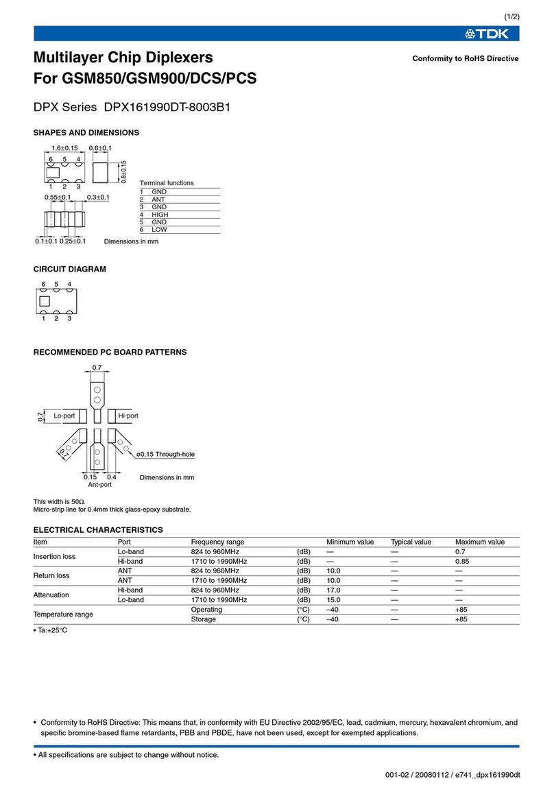
TDK DPX Series DPX161990DT-8003B1 User manual

TDK

TDK DPX Series DPX161990DT-8003B1 User manual

TDK HHM Series HHM1727D1 User manual

TDK

TDK HHM Series HHM1727D1 User manual

TDK Metamere iAA Series Reference guide

TDK

TDK Metamere iAA Series Reference guide

TDK HHM Series HHM1763B2 User manual

TDK

TDK HHM Series HHM1763B2 User manual

TDK Ferrites EE320x250x20 User manual

TDK

TDK Ferrites EE320x250x20 User manual

TDK HHM Series HHM1711E1 User manual

TDK

TDK HHM Series HHM1711E1 User manual

TDK HHM Series HHM1518A3 User manual

TDK

TDK HHM Series HHM1518A3 User manual

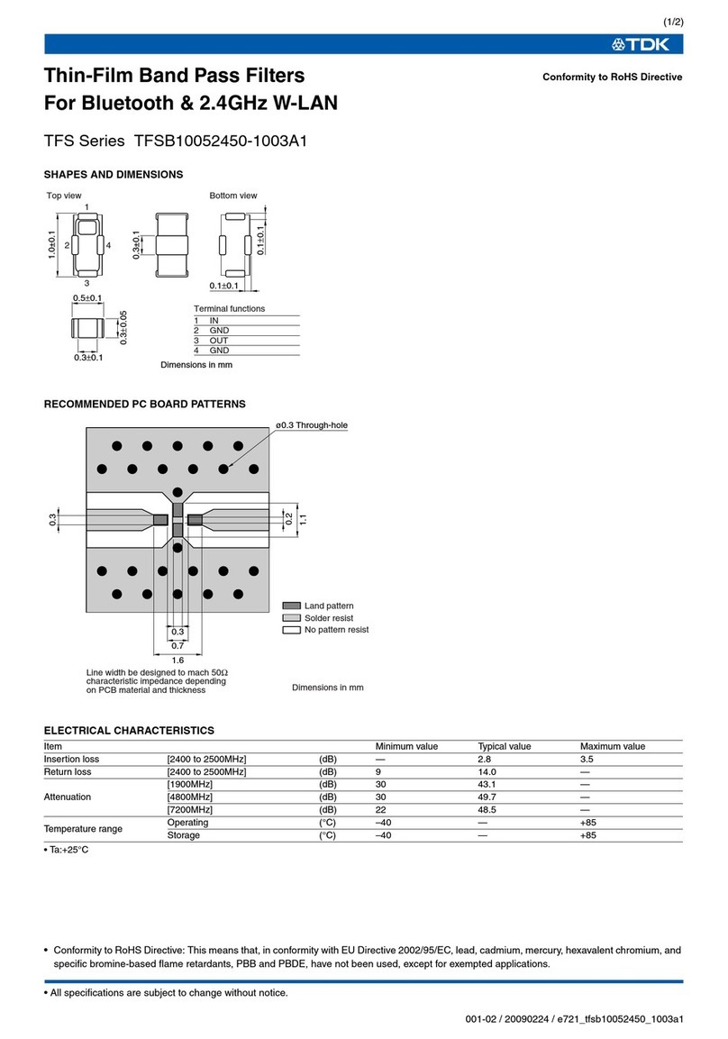
TDK TFS Series TFSB10052450-1003A1 User manual

TDK

TDK TFS Series TFSB10052450-1003A1 User manual

TDK Xeta Half Brick-iHG User manual

TDK

TDK Xeta Half Brick-iHG User manual

TDK HHM Series HHM2411 User manual

TDK

TDK HHM Series HHM2411 User manual

TDK DEA Series DEA165850LT-1197B2 User manual

TDK

TDK DEA Series DEA165850LT-1197B2 User manual

TDK HHM Series HHM2245SA1 User manual

TDK

TDK HHM Series HHM2245SA1 User manual

TDK DEA Series DEA255395BT-2065D2 User manual

TDK

TDK DEA Series DEA255395BT-2065D2 User manual

TDK HHM Series HHM2409 User manual

TDK

TDK HHM Series HHM2409 User manual

TDK Varistors(SMD) AVF16 Series User manual

TDK

TDK Varistors(SMD) AVF16 Series User manual

TDK Powereta iQP 5V/50A User manual

TDK

TDK Powereta iQP 5V/50A User manual

TDK DEA Series User manual

TDK

TDK DEA Series User manual

TDK HHM Series HHM1564A User manual

TDK

TDK HHM Series HHM1564A User manual

TDK EL Series EL0405 User manual

TDK

TDK EL Series EL0405 User manual

TDK TSL Series TSL1112 User manual

TDK

TDK TSL Series TSL1112 User manual

TDK SLF Series SLF12565 User manual

TDK

TDK SLF Series SLF12565 User manual

TDK DEA Series DEA162450BT-1260B2 User manual

TDK

TDK DEA Series DEA162450BT-1260B2 User manual

TDK J Series JBW User manual

TDK

TDK J Series JBW User manual

Popular Computer Hardware manuals by other brands

Intel ECM-APL user manual

Intel

Intel ECM-APL user manual

Sony DVCAM DSBK-2020K installation instructions

Sony

Sony DVCAM DSBK-2020K installation instructions

3Com PC Card user guide

3Com

3Com PC Card user guide

Renesas M30800T-CPE user manual

Renesas

Renesas M30800T-CPE user manual

Fujitsu PG-126 user guide

Fujitsu

Fujitsu PG-126 user guide

ST X-NUCLEO-SRC1M1 user manual

ST

ST X-NUCLEO-SRC1M1 user manual

diapath Donatello user manual

diapath

diapath Donatello user manual

Analog Devices SigmaDSP ADAU1463 manual

Analog Devices

Analog Devices SigmaDSP ADAU1463 manual

Atmel SMART ATBTLC1000 user guide

Atmel

Atmel SMART ATBTLC1000 user guide

A&D EK-03H instruction manual

A&D

A&D EK-03H instruction manual

Powerleap PL-iP3 manual

Powerleap

Powerleap PL-iP3 manual

Advantech PCE-5133 Startup manual

Advantech

Advantech PCE-5133 Startup manual

Adaptec 2045 datasheet

Adaptec

Adaptec 2045 datasheet

Intel RS2BL040 - Raid Controller Hardware user's guide

Intel

Intel RS2BL040 - Raid Controller Hardware user's guide

Arbor Technology EasyBoard-882E user manual

Arbor Technology

Arbor Technology EasyBoard-882E user manual

Icy Box IB-123CL-U3 manual

Icy Box

Icy Box IB-123CL-U3 manual

Sony PDBK-201 Operation and installation guide

Sony

Sony PDBK-201 Operation and installation guide

DFI PCSF51 quick reference

DFI

DFI PCSF51 quick reference

manuals.online logo
manuals.online logoBrands
  • About & Mission
  • Contact us
  • Privacy Policy
  • Terms and Conditions

Copyright 2025 Manuals.Online. All Rights Reserved.