manuals.online logo
Brands
  1. Home
  2. •
  3. Brands
  4. •
  5. Advantech
  6. •
  7. Computer Hardware
  8. •
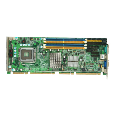
  9. Advantech PCE-5133 Installation and operation manual

Advantech PCE-5133 Installation and operation manual

This manual suits for next models

1

Other Advantech Computer Hardware manuals
Advantech PCA-6151 User manual

Advantech

Advantech PCA-6151 User manual

Advantech PCA-6743 Installation and operation manual

Advantech

Advantech PCA-6743 Installation and operation manual

Advantech SOM-4463 B2 User manual

Advantech

Advantech SOM-4463 B2 User manual

Advantech PCE-7B17-00A1E Installation and operation manual

Advantech

Advantech PCE-7B17-00A1E Installation and operation manual

Advantech PCA-6742 Series Installation and operation manual
Advantech

Advantech PCA-6742 Series Installation and operation manual
Advantech POC-W243 Series User manual

Advantech

Advantech POC-W243 Series User manual

Advantech ASMB-610V3 Installation and operation manual

Advantech

Advantech ASMB-610V3 Installation and operation manual

Advantech PCL-848A/B User manual

Advantech

Advantech PCL-848A/B User manual

Advantech SOM-3565 User manual

Advantech

Advantech SOM-3565 User manual

Advantech PCA-6011 Installation and operation manual

Advantech

Advantech PCA-6011 Installation and operation manual

Advantech RSB-3720 User manual

Advantech

Advantech RSB-3720 User manual

Advantech PCL-740 User manual

Advantech

Advantech PCL-740 User manual

Advantech PCE-3026 Installation and operation manual

Advantech

Advantech PCE-3026 Installation and operation manual

Advantech MIO-2263 Installation and operation manual

Advantech

Advantech MIO-2263 Installation and operation manual

Advantech PCE-5B12-07 Installation and operation manual

Advantech

Advantech PCE-5B12-07 Installation and operation manual

Advantech PCA-6178VE User manual

Advantech

Advantech PCA-6178VE User manual

Advantech USB-4750-AE User manual

Advantech

Advantech USB-4750-AE User manual

Advantech AIMC-3202 Installation and operation manual

Advantech

Advantech AIMC-3202 Installation and operation manual

Advantech PCM-3864 Installation and operation manual

Advantech

Advantech PCM-3864 Installation and operation manual

Advantech EIS-D210 User manual

Advantech

Advantech EIS-D210 User manual

Advantech SOM-5883 User manual

Advantech

Advantech SOM-5883 User manual

Advantech PCI-1716 User manual

Advantech

Advantech PCI-1716 User manual

Advantech FWA-3033-00A1R Installation and operation manual

Advantech

Advantech FWA-3033-00A1R Installation and operation manual

Advantech IPC-610B User manual

Advantech

Advantech IPC-610B User manual

Popular Computer Hardware manuals by other brands

Toshiba TOSVERT VF-MB1/S15 IPE002Z Function manual

Toshiba

Toshiba TOSVERT VF-MB1/S15 IPE002Z Function manual

Shenzhen MEITRACK MVT380 user guide

Shenzhen

Shenzhen MEITRACK MVT380 user guide

TRENDnet TEW-601PC - SUPER G MIMO WRLS PC CARD user guide

TRENDnet

TRENDnet TEW-601PC - SUPER G MIMO WRLS PC CARD user guide

StarTech.com CF2IDE18 instruction manual

StarTech.com

StarTech.com CF2IDE18 instruction manual

Texas Instruments LMH0318 Programmer's guide

Texas Instruments

Texas Instruments LMH0318 Programmer's guide

Gateway 8510946 user guide

Gateway

Gateway 8510946 user guide

Devon IT TC2D Quick setup guide

Devon IT

Devon IT TC2D Quick setup guide

Krüger & Matz Air Shair2 owner's manual

Krüger & Matz

Krüger & Matz Air Shair2 owner's manual

Crystalio VPS-2300 quick guide

Crystalio

Crystalio VPS-2300 quick guide

MYiR FZ3 user manual

MYiR

MYiR FZ3 user manual

Protech Systems BC-K200 Quick reference guide

Protech Systems

Protech Systems BC-K200 Quick reference guide

Miranda DENSITE series DAP-1781 Guide to installation and operation

Miranda

Miranda DENSITE series DAP-1781 Guide to installation and operation

Sierra Wireless Sierra Wireless AirCard 890 quick start guide

Sierra Wireless

Sierra Wireless Sierra Wireless AirCard 890 quick start guide

Leadtek Killer Xeno Pro Quick installation guide

Leadtek

Leadtek Killer Xeno Pro Quick installation guide

Star Cooperation FlexTiny 3 Series Instructions for use

Star Cooperation

Star Cooperation FlexTiny 3 Series Instructions for use

Hotone Ampero user manual

Hotone

Hotone Ampero user manual

Connect Tech Xtreme/104-Express user manual

Connect Tech

Connect Tech Xtreme/104-Express user manual

Yealink WF50 user guide

Yealink

Yealink WF50 user guide

manuals.online logo
manuals.online logoBrands
  • About & Mission
  • Contact us
  • Privacy Policy
  • Terms and Conditions

Copyright 2025 Manuals.Online. All Rights Reserved.

PCE-5133/5033 Startup Manual 1
Packing List
Before you begin installing your card, please make sure that
the following items have been shipped:
1. PCE-5133/5033 PICMG 1.3 single host board
2. PCE-5133/5033 startup manual P/N: 2041513300
3. Serial ATA HDD data cables P/N: 1700003194
4. COM cable with bracket P/N: 1701090401
If any of these items are missing or damaged, please con-
tact your distributor or sales representative immediately.
Note 1: For detailed contents of PCE-5133/5033, please
refer to user manual on the Advantech Website.
Note 2:  AcrobatReaderisrequiredtoviewanyPDFle.
Acrobat Reader can be downloaded at: get.
adobe.com/reader (Acrobat is a trademark of
Adobe)
PCE-5133/5033 - LGA1700 Intel®CoreTM i9/i7/i5/i3/
Pentium®ECC/non-ECC PICMG 1.3 Single Host
Board with DDR5/M.2 (2280)/Dual 2.5GbE LAN
Startup Manual
General
• LGA1700 12th Intel®Core™ i9/i7/i5/i3/Pentium®
• BIOS: AMI 256 Mb SPI BIOS
• Chipset:
- PCE-5133: Intel R680E
- PCE-5033: Intel H610E
• System memory:
- PCE-5133: Supports dual channel DDR5 4800
32GB per DIMM with ECC/non-ECC; Max. capacity is
up to 64GB
- PCE-5033: Supports dual channel DDR5 4800 32GB
per DIMM without ECC; Max. capacity is up to 64GB
Note: Please select Intel ECC supported processor to
enable ECC function.
Warning:Powermustbeturnedo󰀨beforeplugging/un-
plugging memory stick to avoid system crash or
damage of memory stick.
• SATA Ports:
- PCE-5133: 6 x SATA3.0 ports with SW Raid 0,1,5,10.
- PCE-5033: 4 x SATA3.0 ports without Raid function.
• M.2 Ports:
- PCE-5133: M.2 2280 type M module and compatible to
PCI Express 4.0
• Serial ports: 2 x RS-232 with pin headers
• Watchdog timer: 255 level timer intervals
• USB 2.0:
- PCE-5133/5033: 6*USB2.0 (USB Type A*1+Rear*1, 4
on backplane)
• USB 3.2:
- PCE-5133: 6*USB3.2 (Gen1) (Pin-header*6), 2*USB3.2
(Gen2) (type A, Rear I/O)
- PCE-5033: 2*USB3.2 (Gen1) (Pin-header*2), 2*USB3.2
(Gen1) (type A, Rear I/O)
• GPIO: One programmable 8-bit GPIO pin-header
• DP1 & DP2: DVI/Displayport/HDMI via optional cable
VGA Interface
• Chipset: Intel®UHD Graphics
• Shared system memory is subject to OS
Ethernet Interface
• Chipset supports:
- LAN 1: I225LM(PCE-5133); I226V(PCE-5033)
- LAN 2: I225LM(PCE-5133); I226V(PCE-5033)
• Connection: 2 x on-board RJ-45 connectors with LED
indicators.
Note:Powermustbeturnedo󰀨beforeinstalling/unin-
stalling any expansion modules.
Specications
For more information on this and other Advantech prod-
ucts, please visit our website at:
http://www.advantech.com
For technical support and service, please visit our sup-
port website at:
https://advt.ch/PCE-5133G2
https://advt.ch/PCE-5033G2
Register your products on our website and get 2 months
extra warranty for Free at:
http://www.register.advantech.com
This manual is for the PCE-5133/5033
Part No. 2041513300
Printed in China
1st Edition
January 2023
2 PCE-5133/5033 Startup Manual
Mechanical and Enviromental
• Dimensions: (L x W): 338 x 122 mm
• Power supply voltage: +12 V, +5 V, +3.3 V, +5 V
SB
• Power requirements(Idle):
Voltage + 3.3V +5V +12V
Current 8.34A 4.13A 6.86A
Note: Testing conditions:
CPU: Processor: Intel®i9-12900E
Memory: 2 DDR5 4800 32GB
Operating temperature: 0 ~ 60° C (depending on
CPU)
• Weight: 0.5 kg (weight of board)
The board has a number of jumpers that allow you to con-
gureyoursystemtosuityourapplication.Thetablebelow
lists the function of each of the jumpers and connectors.
Connectors
Label Function
COM1 RS-232 (9-pin Box Header)
COM2 RS-232 (9-pin Box Header)
CPU FAN1 4-pin fan power connector for supporting
PWM or DC CPU fan
DP1 & DP2 Display port/DVI/ HDMI via optional
cables
eSPI eSPI expansion pin header for COM
module
HDAUD1 Advantech HD audio module expansion
pin-header
JFP1 Power switch/reset connector
JFP2 External speaker/HDD LED connector/
SMBus connector
JFP3
Power LED
Suspend:fastash(ATX/AT)
Systemon:on(ATX/AT)
Systemo󰀨:o󰀨(ATX/AT)
JPCICLK
PCI clock selection
LAN1 Intel i225LM (PCE-5133)
Intel i226V (PCE-5033)
LAN2 Intel i225LM (PCE-5133)
Intel i226V (PCE-5033)
LANLED1 LAN LED
NVMe M.2 M.2 key 2280 with PCIe Gen. 4
SATA0 &1 Port 0 & 1 (PCE-5133)
SATA4~7 SATA port 4, 5, 6, 7 (PCE-5133/5033)
SPI_TPM1 SPI expansion pin header for TPM
module
Sysfan1 4 PIN fan power connector for support-
ing PWM or DC fan
USB2A1 USB2 port 2
USB2C1 USB2 port1
USB3C1 USB3 port1
USB3C2 USB3 port2
USB3H1 USB3 port 3,4
USB3H2 USB3 port 7, 8 (PCE-5133)
USB3H3 USB3 port 5, 6 (PCE-5133)
VGA1 VGA connector
Jumpers
Label Function
JCMOS1 CMOS clear
JME1 Clear ME data
JPCICLK1
PCI clock selection
JWDT1+
JOBS1 Watchdog timer output and OBS alarm
JPCICLK: PCI clock selection
Closed Pins
Result
1-2
66 MHZ
2-3
*33 MHZ
*Default
66 MHZ 33 MHZ
JESPI1+JESPI2: eSPI-interface COM module setting
Closed Pins Result
JFV1 VGA dummy load setting
JUSB1/
JUSB2 USB power source switch
VGA dummy load setting USB power source switch
JCMOS1/JME1: Clear CMOS/ME data
Closed Pins Result
1-2 Keep CMOS/Enable ME data (Default)
2-3 Clear CMOS/Disable ME data
1 2 3
1 2 3
1 2 3
1 2 3
Specications(Cont.)
Jumpers and Connectors (Cont.)
Jumpers and Connectors
PCE-5133/5033 Startup Manual 3
Jumpers and Connectors (Cont.)
JWDT1+JOBS1: Watchdog timer output and OBS alarm
Closed Pins
Result
2-4, 8-10 Watchdog timer disable (2-4)
OBS beep (8-10)
4-6, 8-10 *Watchdog timer reset (4-6)
OBS beep (8-10)
* Default
Watchdog timer disable (2-4) *Watchdog timer reset (4-6)
OBS beep (8-10) OBS beep (8-10)
JESPI1+JESPI2: eSPI-interface COM module setting
Closed Pins
Result
1-2 Watchdog timer disable (2-4)
OBS beep (8-10)
2-3 *Watchdog timer reset (4-6)
OBS beep (8-10)
* Default
*COM module disabled COM module enabled
Note!
1. Do not change default settings if an eSPI-interface
COM module is not installed; otherwise system will not
turn on.
2. If start to use the COM module, please follow the proce-
dures to prevent system from not to boot up: install the
moduleafterpower-o󰀨,setJESPI1+JESPI2to2-3pins
closed,poweronsystemtoBIOSPOSTscreen,turno󰀨
AC power, then power on.
JFV1: VGA dummy load setting
Closed Pins
Result
1-2 Enable VGA dummy load
2-3 *Disable VGA dummy load
* Default
Enable VGA dummy load *Disable VGA dummy load
Note! It is recommended to leave this function disabled
if you use DVI/DP as your main display.
1 2 3
1 2 3
1 2 3
1 2 3
JUSB_1 & JUSB_2 (onboard USB): USB Power
source switch between +5V and +5V_Dual
Closed Pins
Result
1-2 *USB +5V_DUAL power
2-3 USB +5V power
* Default
*USB +5 V_DUAL power USB +5 V power
The drivers for the PCE-5133/5033 are located on the
Advatecho󰀩cialwebsites.Pleasevisittheo󰀩cialwebsite
for downloading.
https://support.advantech.com/support/new_default.aspx
Caution! The computer is supplied with a battery-powered
real-time clock circuit. There is a danger of explo-
sion if battery is incorrectly replaced. Replace
only with same or equivalent type recommended
by the manufacturer. Discard used batteries ac-
cording to manufacturer’s instructions.
This device complies with the requirements in Part 15 of
the FCC rules. Operation is subject to the following two
conditons:
1. This device may not cause harmful interference;
2. This device must accept any interference received,
including interference that may cause undesired opera-
tion.
1 2 3
1 2 3
Jumpers and Connectors (Cont.)
Software Installation
Declaration of Conformity
4 PCE-5133/5033 Startup Manual
Figure 1: Board Layout: Jumper and Connector Locations
Note: *PCE-5033 supports 4 SATA ports (SATA4~7) and one internal USB3.2 pin-header.
*PCE-5033 does not feature NGFF(M.2).
Figure 2: Board Layout - Jumpers and Connector Locations
Preliminary
System FAN1 DIMMA1
CPU1 DP1 PCH GPIO1 HDAUD1
DP2 COM2 COM1 SPI_TPM1
eSPI
M.2 NVMe
USB3H2 SATA0-1
LANLED1
CPU FAN1 DIMMB1
SATA4-7USB3H3
USB2A1
USB2C1
USB3H1
USB3C2
USB3C1
VGA1
LAN12
JFP1 & JFP2
JFP3
JUSB2
JUSB1
JWDT1 & JOBS1
JCMOS1 JME1
JCASE1
GPIO1
JFV1
JESPI1 & 2
ESPI1
Board Layout