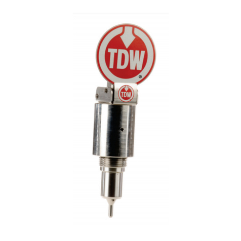
TDW PIG-SIG IV Manual

00-3795-0153 |June 2019
Operating and Maintenance Instructions
PIG-SIG IV
Scraper Passage Indicator
®

© 2019 All rights reserved T.D. Williamson
Notice Any operation involving work on pipe containing
liquids or gases under pressure is potentially
hazardous. It is necessary, therefore, that correct
procedures be followed in the use of this equipment
to maintain a safe working environment.
No person should use this equipment who is not fully
trained in the procedures stated in this manual, and
who is not fully aware of the potential hazards
connected with work on pipe containing liquids or
gases under pressure.
The purchaser of this equipment is responsible for
the way this equipment is used and the training and
competence of the operators.
Should any difficulty arise at any time in the use of
this equipment, please contact T.D. Williamson
immediately.
For Parts and Service:
P.O. Box 3409, Tulsa, OK 74101- 3409 USA
Phone (918) 447-5100
Fax (918) 446-6327
E-mail: [email protected]
Explore the TDW Web site at www.tdwilliamson.com.
™ Trademark of T.D. Williamson in the United States and foreign countries.
® Registered trademark of T.D. Williamson in the United States and foreign country.
Copyright

© 2019 All rights reserved T.D. Williamson
The list below shows the complete revision history of this document
Date
Version
06/2019
Remove T-101a, update measurements, update photos
Document Version History

© 2019 All rights reserved T.D. Williamson i
Section 1:
Safety
1.0 Safety................................................................ 1
Section 2:
Introduction & Installation
1.0 Purpose............................................................. 3
2.0 Description ........................................................ 3
Section 3: Installation
1.0 Nipple Installation............................................. 9
2.0 Plug Installation............................................... 12
3.0 Indicator Installation........................................ 16
4.0 Extended Indicator Installation....................... 22
5.0 Recovering the Plug ...................................... 23
Section 4: Maintenance
1.0 Preventative Maintenance .............................. 26
Table of Contents

© 2019 All rights reserved T.D. Williamson ii
This page intentionally left blank.

Section I – Safety
1.0 Safety 1.0 SAFETY
Throughout this publication, “Dangers,” “Warnings”
and “Cautions” (accompanied by the International ⚠)
are used to alert the customer to special instructions
concerning a particular service or operation that may
be hazardous if performed incorrectly or carelessly.
OBSERVE THEM CAREFULLY!
⚠WARNING
WARNING – Hazards or unsafe practices which
COULD result in severe personal injury or death
and damage to the equipment.
⚠CAUTION
CAUTION – Hazards or unsafe practices which
could result in minor personal injury or product or
property damage.
1.1 General
Ensure the safety features and operating procedures
of the drilling machine are understood. Do not
attempt to make a tap or set a PIG-SIG® V plug
assembly without having a complete understanding
of the drilling machine and of the precautions of
working on pressurized lines.
1.2 Personal Protective Equipment and Clothing
Protective clothing is recommended whenever
working around machinery. Suggestions are: hard
hat, gloves, safety goggles, safety shoes, garments
to cover exposed areas of skin, hearing protection,
and the appropriate breathing apparatus when the
potential for toxic atmosphere exists.
⚠DANGER
DANGER – Immediate hazards which WILL
result in severe personal injury or death.
1

Section I – Safety
This page intentionally left blank.
2

2.0 Introduction
2.1 Purpose
The purpose of this manual is to
provide instructions for the
installation, operation and
preventative maintenance of the
complete TDW PIG-SIGIV
Scraper Passage Indicator and
installation of a PIG-SIG
indicator assembly on a plug
assembly already set in a
pipeline.
2.2 Description
The TDW Scraper Passage
Indicator (PIG-SIG IV) is a
device that is installed on a
pipeline to detect the passage of a
pig or sphere.
The PIG-SIG IV has a trigger that
extends into the pipeline through
a welded fitting that has been
tapped. When a pig passes, the
trigger is tripped, activating the
signaling mechanism.
Signaling mechanisms available
include a flag indicator, electrical
indicator, combination flag and
electrical indicator, or rotary cap
indicator. All indicators are
compatible with all standard plug
assemblies now in the field and
are interchangeable.
This makes it possible to use
these units as conversion kits as
well as complete PIG-SIG
Indicators.
The PIG-SIG IV is weatherproof
and corrosion resistant. It features
housings manufactured from
space age plastic for durability
and weather resistance. The flag
indicator offers high visibility
from the air or ground.
The carbon steel nipple is
manufactured from easily
weldable material. The PIG-SIG
Plug Assembly can be installed
on or removed from a pressured
pipeline using a TDW T-101 or
T-101b Drilling Machine and
accessories.
The PIG-SIG IV is available in
various combinations of
operation, indication and
materials of construction,
depending on piping
requirements, including:
•Flag Indicator with Manual
Reset flag
•Rotary Cap Indicator with
Manual Reset
•Electrical Indicator with Auto
Reset
•Flag/Electrical Indicator with
Auto Reset
•Indicator Extensions from 1
foot to 15 feet
•Unidirectional or Bidirectional
Trigger Mechanisms
•Special Materials and O-Ring
Seals
•Models for Environmentally
Harsh Conditions
3

•Weld-on Nipple or Flanged
Mounting
•Stainless or Brass Plug
Assemblies
•"Build Your Own" PIG-SIG
IV Assembly (See Appendix.)
Shown in Figure 1 is the manual
reset with flag indicator model.
Within the above four types, the
PIG-SIG IV is available in
several variations, including such
options as bi-directional or
unidirectional detection, O-ring
material and material used in plug
construction. Several extension
lengths are available to elevate
the indicator. The "Build your
own PIG-SIG" charts at the end
of this manual show all the
variations available.
The PIG-SIG IV also can be
installed on a line under pressure,
without taking the line out of
service, using the TDW T-101 or
T-101b Drilling Machines. This
manual includes installation
procedures for each drilling
machine.
Figure 1. Manual Reset with Flag
Indicator
4

2.2.1 Specifications
A. THREAD-O-RING Nipple Material
THREAD-O-RING Nipple Material Specification:
Size & Grade:
2 NPS XXS, ASTM A 333 Grade 6 seamless steel pipe.
Tensile Requirements:
35,000 psi SMYS – 60,000 psi SMTS
Impact Requirements:
13 ft-lbf min Avg 3 Specimens
10 ft-lbf min One Specimen Only
Impact Temperature: -50 º F
Chemical
Requirements:
Composition Percentage:
Carbon: 0.30 max; Manganese: 0.29-1.06; Phosphorus:
0.025 max; Sulfur: 0.025 max; Silicon: 0.10 min
Test Report:
Certified test reports furnished per ASTM A 530
5

2.2.2 Pressure-Temperature Ratings
PRESSURE-TEMPERATURE RATINGS FOR
PIG-SIG IV SCRAPER PASSAGE INDICATOR
THREAD O-RING NIPPLE
(Does not include allowance for corrosion.)
Pressures are in pounds per square inch, gauge (psig)
Piping Code
B31.3
B31.4
B31.8
Temp.
°F
F=.72
F=.72
F=.60
F=.50
F=.40
-50
-20 to
250
3743
3743
3120
2600
2080
300
3159
3620
3017
2514
2011
350
3493
2911
2425
1940
400
3369
2808
2340
1872
450
3072
3246
2246
1872
1497
500
2985
Note: O-Ring material selection must be suitable for service fluids and
temperature requirements.
B. Electrical
Electrical Indicator Switch Specifications:
Double-pole, 2 N.O., 2 N.C.
Momentary (¾-inch conduit)
Electrical Ratings:
10 amps continuous carry. Circuits on any one pole must be the same polarity.
MICRO SWITCH1weather-sealed explosion-proof switch BXP4L is designed
specifically for use in hazardous location applications. The switch enclosure is
sealed for protection against corrosion, water, dust and oil as defined in NEMA
6

1,3, 4, 4X, 6, 7, 9 and 13 and IP67 as defined in IEC 529. The switch enclosure
meets the European Hazardous Locations Designation: EExd IIC T6 category II
2 GD, SIRA 00ATEX 1037X. The switch complies with the European Directive
on Equipment and Protective Systems Intended for Use in Potentially Explosive
Atmospheres (94/9/EC) commonly referred to as the ATEX Directive.
Compliance with the Essential Health and Safety Requirements has been
assured by compliance with EN50014 1997 and EN50018 1994. The switch
meets the North American Hazardous Locations Designation: Class I, Groups B,
C and D; Class II, Groups E, F, and G. The switch complies with UL (File No.
E61730) and CSA (File No. LR57327). The switch operating temperature range
is -40ºF (-40ºC) to 158ºF (70ºC). The switch housing is epoxy coated Aluminum
and Zinc with Fluor silicone seals.
AC Volts – Pilot Duty: 600 VAC, 720 VA
Circuitry
VAC
Make
Break
240
15
1.5
Double-Pole
Double-Throw
480
7.5
0.75
600
6
0.60
DC Volts – Pilot Duty: 240 VDC, 30 Watts
Circuitry
VDC
Inductive
Resistive
24
10
10
Double-Pole
Double-Throw
120
0.25
0.8
240
0.15
0.4
NEMA Types
Non-Hazardous Locations
Hazardous Locations
1
3
4
4X
6
6P
12
13
7B
7C
7D
9E
9F
9G
•
•
•
•
•
•
•
•
•
•
•
•
Amps at 0.35 Power Factor
Make and Break Amps
7

C. Reference Standards
Non-Hazardous Locations
Type I enclosures are intended for indoor use primarily to provide a degree of
protection against contact with the enclosed equipment.
Type 3 enclosures are intended for outdoor use primarily to provide a degree of
protection against windblown dust, rain, sleet, and external ice formation.
Type 4 enclosures are intended for indoor or outdoor use primarily to provide a
degree of protection against windblown dust and rain, splashing water and hose-
directed water.
Type 4X enclosures are intended for indoor or outdoor use primarily to provide
a degree of protection against corrosion, windblown dust and rain, splashing
water and hose-directed water.
Type 6 enclosures are intended for indoor or outdoor use primarily to provide a
degree of protection against the entry of water during occasional temporary
submersion at a limited depth.
Type 13 enclosures are intended for indoor use primarily to provide a degree of
protection against dust, spraying of water, oil and non-corrosive coolant.
Hazardous Locations
Type 7 enclosures are for use indoors in locations classified as Class I, Groups
B, C, or D as defined in the National Electrical Code.
•Group B - Atmospheres containing hydrogen manufactured gas.
•Group C - Atmospheres containing diethyl ether, ethylene or cyclopropane.
•Group D - Atmospheres containing gasoline, hexane, butane, naphtha,
propane, acetone, toluene or isoprene.
Type 9 enclosures are for use indoors in locations classified as Class II, Groups
E, F, or G, as defined in the National Electrical Code.
•Group E - Atmospheres containing metal dust.
•Group F - Atmospheres containing carbon Hack, coal dust or coke dust.
•Group G - Atmospheres containing flour, starch or grain dust.
8

Conforming
International Standard
Type of Protection
NEMA
IEC
Rain Tight
Type 3
IP-63
Water Tight
Type 4
IP-65
Submersible
—
IP-67
Oil Tight/Dust Tight
Type 13
—
3.0 Installation
3.1 Nipple Installation
3.1.1 Pre-cut Hole vs.
Tapping the Line
A THREAD-O-RING nipple may
be installed over a pre-cut
opening in the pipe, or the
opening may be cut using a
drilling machine with a 1-7/16-
inch drill after the nipple has been
welded to the pipe. A pre-cut
opening must be 1-7/16- to 1-
1/2-inch diameter through the
pipe wall, and the bore of the
nipple must be coaxial with the
hole cut in the pipe to within
1/32-inch. No part of a
THREAD-O-RING nipple may
extend inside the pipe for
reinforcement or for any other
purpose. If additional
reinforcement is required,
THREAD-O-RING nipples can
be provided for attachment to
various types of integrally
reinforced connections.
CAUTION: The PIG-SIG plug
assembly can be damaged,
and may not operate
properly, if the THREAD-O-
RING nipple is not installed
correctly, or the opening in
the pipe is too small.
3.1.2 Welding Instructions
A. Weld procedures and welders
should be qualified to current
API 1104, API 1107 or ASME
Section IX.
B. Low hydrogen electrode
AWS-E-XX18 is
recommended for use with
TDW fittings. The use of
low-hydrogen electrodes is
specifically recommended by
certain welding specialists
when the nipple is to be
welded to pipelines operating
in a high moisture area and/or
a temperature below 50º F.
Use of AWS-E-XX18
electrodes helps avoid cracks
that can result from stress
produced during solidification
of weld metal and help avoid
hydrogen-induced cracking.
Consult the manufacturers of
such electrodes for proper care
9

and use.
C. Clean all weld edges
thoroughly. Remove all paint,
dirt, rust, oil, etc., from the
weld areas.
D. Position the nipple so that it is
on the centerline of the pipe
and perpendicular to the
surface of the pipe. A nipple,
which is intended to receive a
unidirectional trigger
assembly, may be installed in
any position around a pipe
oriented in any direction
relative to horizontal. A
nipple, which is intended to
receive a bidirectional trigger
assembly, must be installed
only on top of a horizontal
pipeline.
E. If moisture is on the line, dry
the area where the nipple will
be located to remove the
moisture before installation is
started. This is important in a
high-moisture area.
F. Remove PIG-SIG plug from
nipple. Be careful not to
damage plug threads or trigger
mechanism. Put some type of
protective cover, such as a 2-
inch plastic pipe cap, over the
threaded end of the nipple.
G. For proper weld penetration a
root gap should be introduced
between the weld-end of the
nipple and surface of the pipe.
Do not exceed 1/8-inch root
gap. DO NOT WELD
INSIDE of the nipple and be
careful to prevent excessive
weld penetration inside the
nipple to help avoid tapping
problems. The length of the
nipple varies according to pipe
wall thickness. For
installation on 6-inch and
larger pipe, the sum of the
nipple length, root gap, and
pipe wall thickness should be
4-1/4- to 4-1/2-inches. If that
combination of values exceeds
4-1/2-inches, grind some off
the weld-end of the nipple,
obtain a shorter nipple, or
decrease the amount of root
gap.
WARNING: Follow established
welding standards
when welding the
nipple onto the line.
Improper welding can
cause rupture of the
pipeline during or
after welding.
H. Upon completion of welding,
remove the cap from the
nipple.
I. Clean internal and external
threads of the nipple.
J. Inspect the welded area inside
thenipple. Remove any loose
weld spatter or bead.
10

K. The weld area should be
allowed to cool before tapping
the line. Normally, it will cool
sufficiently while the tapping
equipment is being prepared.
3.1.3 Tapping the Line
A. Apply thread sealant to the
external pipe thread of nipple
and thread tapping valve onto
nipple. The valve must be
rated to at least line pressure
andmust have a minimum
through bore of 2-1/16-inch to
permit passage of the TDW
PIG-SIG plug assembly.
CAUTION: Do not overtighten the
valve. Overtightening can
swage the nipple diameter too
small to install the PIG-SIG
plug assembly. Before
making tap, check PIG-SIG
plug clearance.
B. Grasp trigger of plug and pass
plug assembly upside down
through tapping valve bore
into nipple, as shown in Figure
2. If the top of the plug turns
freely in the nipple, the nipple
has not been distorted.
Figure 2. Check Nipple for Swaging
C. When taking tapping
measurements, as prescribed
in the drilling machine
manual, another measurement
is required, which will be used
in setting the plug. Measure
from the top of the valve face
to the top of tapping fitting as
shown in Figures 3 and 10.
Label this measurement “J”
and retain for use when setting
the plug.
D. Prepare T-101 or T-101b
drilling machine with a 1-
7/16th inch drill, install and
tap through pipe, following
instructions in drilling
machine manual.
11

Figure 3. Measurement J
E. Close tapping valve, bleed
pressure and remove drilling
machine.
WARNING: Vent pressure bleeder
valve away from work
area and personnel.
Stand clear of vent
when bleeder valve is
opened. Otherwise,
personal injury may
result from blowing
material.
3.2 Installation of the Plug
Installation of the plug is the
same for all four PIG-SIG types.
The nipple must be welded so
that it is on the centerline of the
pipe and perpendicular to it. The
unidirectional assembly may be
installed in any position around a
pipe oriented in any direction
relative to horizontal. The bi-
directional assembly must be
installed on top of a horizontal
pipeline.
When installing an indicator
assembly on a plug assembly
already installed in a line, begin
with paragraph 4.3.
3.2.1 Preparation for Setting
the Plug
A. Extend drilling machine
boring bar until retainer ring is
exposed.
B. Insert plug holder into boring
bar and install retainer spring.
See Figure 4.
Figure 4. Insert Plug Holder
C. Install plug assembly on plug
holder, aligning arrow on top
of plug with arrow on hex
drive of drilling machine.
(Figure 5). Balls in plug
holder must seat into plug
well. Plug must not be
positioned against plug holder
shoulder. Refer to Figure 6.
12

Figure 5 Align Plug Assembly Arrow
Figure 6 Position Plug
D. Lubricate Plug Assembly O-
ring.
Figure 7. Install Valve Adapter
E. Apply thread compound to the
external threads of adapter and
install threaded valve adapter
on drilling machine. See
Figure 7.
F. Fully retract plug assembly
into the adapter. Make sure
zero is visible on the body
tube. See Figure 8.
Figure 8. Retract Plug Assembly
3.2.2 Compute Plug Setting
Distance
It is important that the distance
required to completely set the
plug be known. Measurements
are taken at this time to determine
that distance.
A. Measure from the end of the
adapter to the bottom of the
threads of the plug assembly
and mark this measurement on
the outside of the adapter,see
Figure 9. Label this
Measurement "G".
B. Install drilling machine on
tapping valve. Use thread
compound on adapter threads.
13

Figure 9. Measurement G
C. Measurement “J” (see Figure
3), the distance from the valve
face to the top of the tapping
fitting, was taken prior to
making the tap.
D. Measurement “K”, a constant
1-7/8-inches for all PIG-SIG
models, is the distance from
the top of the tapping fitting to
the point where the plug is
completely set in the fitting.
E. The sum of Measurements
“G,” “J,” and “K” should be
the body tube reading when
the plug is completely set.
Mark this measurement on the
drilling machine body tube.
See Figure 10.
Figure 10. Plug Setting Measurements
CAUTION: Measurements must not
exceed 18 inches, the
maximum travel distance of
the T-101b Drilling Machine.
If setting distance exceeds 18
inches, a different tapping
machine, such as the T-101
XXL, will be required.
3.2.4 Setting the Plug
A. Install bleeder valve on
drilling machine and open
bleeder valve (Figure 11).
B. Open the tapping valve
slightly to purge air through
bleeder valve on drilling
machine and when air is
purged, close bleeder valve.
C. Check the adapter connections
for leaks and then open
tapping valve to full-open
position.
14

Figure 11. Install Bleeder Valve
WARNING: Vent pressure bleeder
valve away from work
area and personnel.
Stand clear of vent
when bleeder valve is
opened. Otherwise,
personal injury may
result from blowing
material.
D. Hold hex drive and rotate feed
tube clockwise until feed tube
is 2 in. from mark on body
tube. Stop rotation.
Figure 12. Lock Boring Bar
E. Install locking cap. This locks
the feed tube and boring bar
together permitting extension
and rotation of the boring bar
at the same time.
Figure 13. Lower the Plug
F. Attach handle to ¾ in. hex
drive. Do not use air motor for
completion plug setting
operations. See Figure 13.
G. Rotate handle clockwise until
mark is reached on body tube
and plug is tight inside fitting.
Do not over-tighten or the O-
ring and threads may be
damaged.
H. Turn lower-in crank
counterclockwise until arrow
on hex drive aligns with flow
in the pipeline. This aligns
plug assembly in the nipple.
I. If measurements correspond,
check the seal on plug by
removing the crank handle and
locking cap.
J. Retract boring bar 2 in. and
open bleeder valve. If pressure
bleeds off, plug is set.
NOTE: If pressure does not bleed
off, plug is not properly set.
Recheck measurements to
make sure full travel distance
has been reached. If full travel
distance has been reached and
pressure does not bleed off,
pressure is probably leaking
around O-ring. Close bleeder
15
Table of contents
Other TDW Measuring Instrument manuals
Popular Measuring Instrument manuals by other brands
Draper
Draper PVC150D Specifications
FISCHER
FISCHER MA15F ... A Series Operation manual
Zeiss
Zeiss MEL 80 manual

Horiba Scientific
Horiba Scientific LAQUA-PD210 instruction manual
RKI Instruments
RKI Instruments GX-6000 Operator's manual
PCB Piezotronics
PCB Piezotronics IMI SENSORS 645B01 Installation and operating manual
Mitsubishi Electric
Mitsubishi Electric EcoMonitorPro EMU2-RD3-F instruction manual

ANDERSON-NEGELE
ANDERSON-NEGELE IZMSA operating manual
Inficon
Inficon PCG550 manual
Dragino
Dragino LHT65N user manual

Burster
Burster DIGIFORCE 9310 manual

Endress+Hauser
Endress+Hauser PROFIBUS PA Proline Promass 80 operating instructions
