TESA Micro-Hite Plus M User manual

M
1
TESA Micro-Hite®
Plus M
Base instrument,
1D Control Panel
and Accessories
Instruction Manual
Français
English

M
2

M
3
1General features page 04
2 Installation page 06
2.1 Unpacking and setting up page 06
2.2 Getting started page 06
3 Key components page 08
3.1 Height gauge base page 08
3.2 Air-bearing base page 08
3.3 Vertical column, measuring head, head displacement page 08
3.4 Rotary power control page 08
3.5 Power supply page 11
3.6 Measuring system page 11
3.7 Automatic value correction page 11
3.8 Control panels page 12
4Measuring page 12
4.1 General page 12
4.2 1D Control panel with function keys page 14
4.3 Power Panel plus M with function keys page 16
4.4 Probing procedure at the contact point page 17
4.5 Establishing the probe constant page 20
(for length measurements with inversion of the probing direction)
4.6 Programming retraction travel page 22
4.7 Capturing a reference value page 23
4.8 PRESET mode page 25
4.9 Measuring grooves page 27
4.10 Measuring ribs page 29
4.11 Measuring bores page 30
4.12 Measuring shafts page 32
4.13 Calculating distances page 34
4.14 Measuring centre distances of threads page 37
4.15 Measuring flatness or parallelism on flat surfaces page 38
4.16 Measuring deviations from perpendicularity using a dial-test indicator page 40
4.17 Measuring deviations form perpendicularity or straightness using page 40
a TESA IG-13 digital probe
5 Maintenance page 42
5.1 General cleaning page 42
5.2 Recharging batteries page 42
5.3 Changing worn-out batteries page 42
6 Delivery programme page 43
6.1 TESA Micro-hite plus M height gauges page 43
6.2 Control panels page 44
6.3 Optional accessories page 45
7 Technical data page 50
7.1 RS 232 digital interface page 51
7.2 Monodirectional data transmission page 51
7.3 Bidirectional data transmission page 51
8 Warranty page 51
9 Declaration of conformity page 52
TABLE OF CONTENTS

M
4
1 GENERAL FEATURES
Cover plate 1
Transmission band 2
13Setting screw for air-cushion
9Handle
10 1D control panel
11 Switch for electric pump
12 Rotary power control
8Three-point cast-iron base
Housing 3
Mounting pin 4
Probe fixing arm 5
Probe 6
Guiding face with resting points 7
Fig. 1

M
All TESA Micro-hite plus M of the latest generation
are different from the other height gauges in that
they have exceptional metrological capabilities and
can be used intuitively with ease. The unique and
revolutionary rotary power control combines the
speed of a manually operated height gauge with the
precision and easy handling of a motorised one.
Each of them incorporates a number of new fea-
tures for which patents are pending.
These height gauges are specially designed for
measuring lengths in the form of internal, external,
step, height or depth dimensions as well as dis-
tances. Their concept also permits, for instance,
deviations from straightness and perpendicularity
to be measured.
Every TESA Micro-hite plus M is mechanically
adjusted at our premises based on a TESA’s
patented system, thus allowing random errors in
perpendicularity to be quickly and easily detected
using a dial test indicator.
Value processing is ensured via the control panel.
With their modular concept, TESA Micro-hite plus
M offer an individual solution to each measuring
application.
The Power Panel plus M, which may be provided
with or without built-in printer, can be used besides
the 1D control panel – thus enabling single or two
coordinate measurements to be carried out as well
as bore position to be determined, both in polar and
rectangular coordinates. Furthermore, this panel
can measure straightness and perpendicularity
along with angles. It also allows direct connection
ofa measuringinstrument fittedwith anRS232 dig-
ital output.
The heavy cast-iron base features three resting
points precisely ground to ensure high stability.
Once integrated, the electric pump generates the
air-cushion so that your height gauge can easily be
moved across the surface plate.
The rigid column under the housing includes the
guiding part that is rigorously straight and perpen-
dicular to the base. The patented opto-electronic
system measures any head displacement.
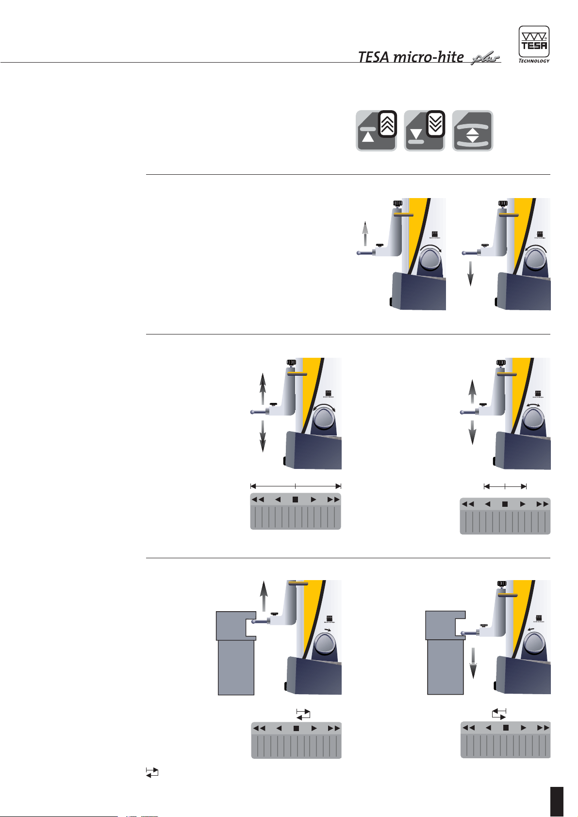
Value acquisition is very simple and reliable. Rotating
the power control or activating the appropriate func-
tion key causes the insert to move to the point to be
probed automatically. The measured value is then
captured after a wait for stabilisation. A constant
measuringforceis ensured bythe mechanicalfriction
release mechanism, which has been specially devel-
oped for this purpose. An acoustic signal confirms
the capture of the measured values, which are dis-
played at once and further transferred via the RS out-
put provided they are judged to be correct.
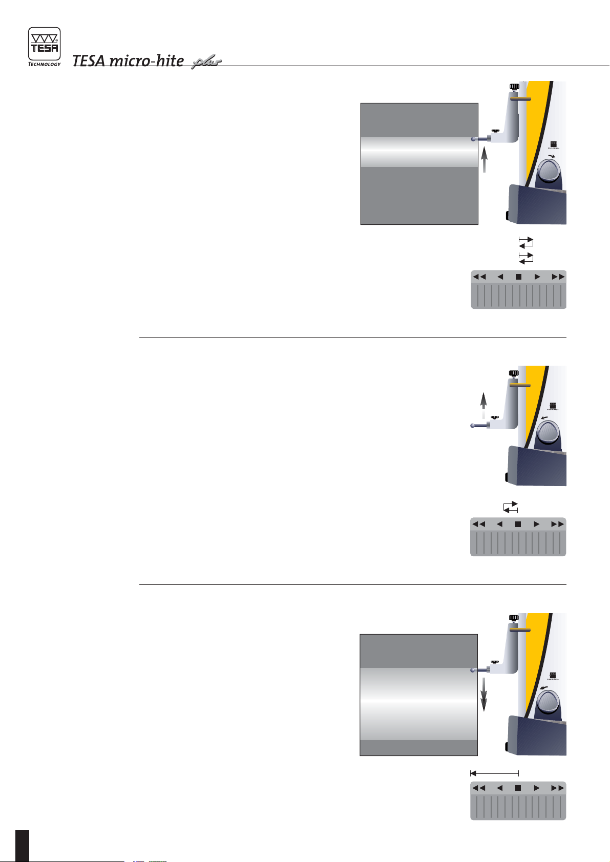
Round-shaped cylindrical surfaces (e.g. bores or
shafts) can equally be inspected easily and reliably
through automatic detection of the culmination
point.
The computer-aided value correction enhances the
accuracy of every TESA Micro-hite plus M even fur-
ther. The correction values stored in the electronics
compensate for the bias errors when measuring
lengths.
Continuous mains independent operation is
ensured by the rechargeable battery pack with no
cumbersome cables or power cord to hinder the
operator.
1 GENERAL FEATURES
5

M
6
2.1
Unpacking and
setting up
TESA Micro-hite plus M is supplied in a special
boxgiving protectionagainst shocksand corrosion.
Keep this box for use whenever the instrument is
transported at a later date.
–First lay the box flat, then carefully lift the height
gauge and place it on a safe surface. For this
operation, ask for the help of someone else.
–Stand the instrument up on the clear surface
plate.
–Fix the control panel on the articulated support
and tighten with screw.
For safe transportation of your height gauge from a
surface plate to another, we advise to use the han-
dle set N° 00760129 available as an option.
2 INSTALLATION
2.2
Getting started Activate the electric pump using the relevant switch
(11) to generate the air-cushion for easy displace-
ment.
Next, start the height gauge by pressing key
for more than one second .
ON
OFF
Starting up
ON
OFF
This causes the measuring head to move past the
referencemark andposition itselfat thepoint where
the master piece is located. Head displacement can
be accelerated by using either the handle or the
rotary power control.
Displayed value once the head has travelled past
the reference mark
Start capturing probe constant value by pressing
key or which is used for groove measure-
ment.
For more details, report to chapter 4.5.
0
ON
OFF

M
7
St 1
Probe
datum point
Cancel
reference
Probe constant
capture
St 2
Probe
datum point
Switch the instrument on
Using the
1D control panel
(N° 00760216)
Using either of both
Power Panels Plus M
(N° 00760220
or 00760221)
Probe insert moves automatically, travels past the reference mark of the precision glass scale for initialisation,
then places itself into position at the centre of the master piece.
ON
OFF
Cancel
reference
Measure Measure
St 1
Probe
datum point
Cancel
reference A or B
Probe constant
capture
St 2
Probe
datum point
Switch the instrument on
Access mode
for perpendicularity
measurement?
Probe insert moves automatically, travels past the reference mark of the precision glass scale for initialisation,
then places itself into position at the centre of the master piece.
ON
OFF
Cancel both
references A and B Cancel
reference A or B
Measure Measure
Cancel both
references A and B
yes
no
no
no
Is TESA IG-13
connected?

M
8
3.1
Height gauge
base
Rugged nickel plated base for high resistance to
corrosion. The precision ground bottom face
includes three supporting points which are finely
lapped to guarantee high stability to your TESA
Micro-hite plus M. They form together a large sur-
face so that grooves and slots on the surface plate
can be safely run over.
The faces 7 (Fig.1, page 4) are specially designed to
allow TESA Micro-hite plus M to rest on or be
guided in straight-line along the length of a rule, for
instance.
3.2
Air-bearing
base
The air-bearing base, which is generated by the
pneumatic system linked to the electric pump
N° 00760142 integrated into the main part, permits
the height gauge to be moved safely and easily.
Once activated, the pump creates an air-cushion
only a few µm thick between the height gauge base
and the surface plate so that TESA Micro-hite plus
M can be displaced effortless and quite wear-free.
The thickness of the air cushion can be set accord-
ing to the surface quality of the granite plate. This is
done by turning screw 13, which acts on the valve
located into the pneumatic system.
Experience has shown that the air cushion should
not be thicker than necessary. Once enabled, it has
to support the weight of the height gauge while
contacting the surface plate lightly.
3.3
Vertical column,
measuring head,
head displacement
The rigid column is mounted at right angle to the
base, into fix position. As the measuring head is
sliding along the guiding part, its displacements are
captured by the opto-electronic measuring system
(TESA’s patent). A counterweight is mounted on the
steel tape supporting the measuring head. This
enables it to stand still in any position with use of
the accessories that came with your TESA Micro-
hite plus M.
Head displacement is electro-motorised. This
includesaservomotordrive whichallows you toset
the speed at which you want the head to be shifted,
conveniently. The specially designed friction mech-
anism ensures a constant measuring force during
the measurement operations.
3 KEY COMPONENTS
3.4
Rotary power control This new feature with its unique and revolutionary
design is located close to the base. It serves for
shifting TESA Micro-hite plus M on the air-bearing,
for commanding fast motion of the probe insert as
well as for triggering all main measuring functions.
Since the rotary power control is used intuitively,
the instrument moves quickly and precisely across
the surface plate. It needs just be rotated clockwise
or counterclockwise for approaching the measuring
point whether quickly or slowly, probing up and
down or performing bore measurement.

M
9
Operating functions using the rotary power
control
Usually, these functions are identical to those of
the probe insert.
Ways to move the probe insert
–Turn the rotary power control clockwise to move
it up (Fig. 1).
–Turn the rotary power control counterclockwise
to move it down (Fig. 2).
Fast displacement Positioning
probe insert
A continuous rotation
causes the probe insert
to move even faster
(according to the angle
the power control is
rotated) and to deceler-
ate or stop when
approaching the zero
point
(■)
or releasing
the rotary power con-
trol.
Probing down
Short rotation (< 0,7 s) in the probing direction.
4
1
.
Fig. 1 Fig. 2
Probing up

M
10
Fast displacement
When measuring bores or grooves, this function
can be enabled to shift the probe faster from the
upper to the lower point and the other way round.
Bore measurement
A second short rotation of the power control in the
same direction permits bore measurement with
detection of the culmination point.
–Turn the power control clockwise to start probing
the upper point.
–Turn the rotary power control counterclockwise,
to start probing the lower point first.
1
2
Stop
A second or third short rotation in reverse
direction causes the probe insert to stop.
– Selected measuring function is then quit.

M
11
3.5
Power supply TESA Micro-hite plus M is provided with the bat-
tery pack N° 00760141, which can be charged
using the mains adaptor (N° 04761054) along with
either of both cables EU 04761055 or US 04761056
(see chapter 5.2 – Recharging the battery pack).
Use of a second battery pack (optional) provides
full autonomy as one can be recharging while the
other is in use. Continuous operation is thus made
easier as there are no cables to clutter up the oper-
ator working on the surface plate.
The battery pack is also used for powering the con-
trol panel directly connected to the height gauge.
3.6
Measuring system TESA Micro-hite plus M incorporates an opto-elec-
tronic measuring system (TESA’s patent), which
catchesthe measuredquantity (alsoknown asmea-
surand) digitally. The glass scale with both incre-
mental graduations and reference mark serve as
material measure. According to the principle of the
reflected light, each graduation is scanned by the
photocells inside the optical sensor, with no
mechanical contact. As next step, the measurement
signal is transmitted to the control panel, which
operates an analogue/digital conversion.
The probing procedure is either started by activat-
ing a measuring function or rotating the power con-
trol. As soon as the measuring insert enters into
contact with the point to be probed, the friction
clutch ensures a constant measuring force . After a
wait for stabilisation, the measured value is
processed through the control panel.
3.7
Automatic value
correction
It is agreed that producing a perfectly accurate
measuring instrument is quite impossible.
Consequently, any displayed value shows a devia-
tionfrom theexact value,whichis moreorless sig-
nificant. This deviation mainly includes the system-
atic (bias) errors and random errors of the
measuring instrument being used. The latter often
result from influences which can not be predicted –
e.g. value dispersion.
On the other hand, any detectable systematic
errors can be compensated for by corrections.
These errors may be due to inaccuracies in the
graduations of the material measure or to form and
position errors of the head guides.
TESA Micro-hite plus M is able to execute the auto-
matic correction of the measured values through
CAA (computer-aided accuracy) while taking bias
errorsinto account.This isdone intwo ways: while
one is based on the measured lengths, the other
refers to both perpendicularity and straightness
checked with the aid of a TESA IG-13 digital probe
(N° 00760139) listed under optional accessories
(this probe can only be used with the Power Panel
Plus M).
Straightness and perpendicularity errors are first
corrected once the main part has been entirely
assembled.
TESA Micro-hite plus M is calibrated on the high
quality surface plate with the aid of a high accuracy
masterangle square to 90°;both featuresaremade
of granite – a hard (usually grey) stone. The meas-
urements are carried out in both measuring direc-
tions (frontal and lateral) with use of a TESA GT-21
electronic probe, which only serves as reference at
our plant. The EEPROM memory inside the main
part includes a correction table for each direction. It
should be noted that automatic value correction
cannot be activated unless TESA IG-13 probe is
connected. With regard to this, report to chapter
4.13.
Length values are corrected based on the actual
deviations previously determined step by step at
eachprobing point throughoutthe measuringrange
using reference gauge blocks. These deviations are
then captured by the computer used for calculating
all correction values and further stored in the elec-
tronics (EEPROM) for automatic correction using
the 1D control panel or the Power Panel plus M.
Note
When the height gauge is switched on, the control
panel will read all stored values during the initialis-
ing procedure (display shows the Init sign).

M
12
3.8
Control panels The modular concept of your TESA Micro-hite plus
M makes it possible for the measured values to be
captured and further processed separately. So they
are first measured on the workpiece being
inspected, then transferred to the control panel for
correction, processing and displaying. Necessary
allowances are made for the systematic errors.
You may either connect the 1D control panel or one
of both Power Panel plus M (with or without built-in
printer). To switch the height gauge on or off, press
this key on the relevant control panel, which also
provides various interfaces.
F1 F2 F3 F4 F5 F6
I
7
÷
+
*
(=)
89
456
123
0
BA
P
W
RS
2D
G
N
H
O
F
M
UVT
JKL
CDE
QRS
XYZ
SP
1D control panel
Model No. 00760216
This model includes the following features:
–RS 232 serial interface for bi-directional data
transmission.
–input for the foot switch used to activate the
PRINT function or repeat last measuring
function.
Power Panels Plus M
Model No. 00760220 or 00760221
–First model comes with built-in printer.
Both models include the following features:
–RS 232 serial interface for bi-directional data
transmission;
–input for equipment with RS 232 interface;
–input for TESA IG-13 digital probe;
–input for the foot switch used to activate the
PRINT function or repeat last measuring
function;
–CENTRONICS output for A4 printer.
4.1
General The way TESA Micro-hite plus M will execute a
value acquisition often depends on the measuring
application,whichis mainly basedon the following:
–Measuring without inversion of the probe
direction (St1).
– Measuring with inversion of the probe
direction (St2).
–Detecting form, parallelism or run-out errors.
–Measuring perpendicularity errors using
TESATAST.
– Measuring perpendicularity and straightness
with the aid of TESA IG-13 probe (only with
connected Power Panel Plus M).
– Measuring angles (only with connected Power
Panel Plus M).
–Measuring in two coordinate directions (only
with connected Power Panel Plus M).
4 MEASURING
ON
OFF PRINT
1
2
n
87
mm
in
9
654
.
321
0

M
13
Capturing form and position errors
Measuring without inversion of the probing
direction
Making no allowance for the probe constant
–with no storage of the culmination point –with storage of the culmination point
Measuring with inversion of the probing
direction
Making allowance for the probe constant
h2
h1
h4
h3
h2
h1
h4
h3
h4
h1
b2 b1
h3
h2
h2
h1
ø2 ø1
h3
.../L
.../L
0
0
0
Y
X
0
YW
XW
0
YG
XG
A
6x ø... A
Measuring in two coordinate directions
Parallelism
error Radial
run-out error
«max»
«min»
«max»-«min»

M
14
4.2
1D control panel
with function keys
(N° 00760216)
Press this key to turn the height gauge on
or off and keep pressing (> 0.6 s) to get
confirmation.
Press shortly (< 0.6 s) to transfer the value
from main display to a peripheral device.
Keep pressing this key (> 0.6 s) to transfer
full table contents (including up to 99
numbered values) to a peripheral device.
Press to reset counter to zero. This key
also allows headings to be printed provid-
ing the relevant dip switches are appropri-
ately set to enable language selection.
Note: Press CANCEL key to restore earlier
version of the measurement table.
Press to cancel last function or probing
operation.
Press to measure the centre, then the
width of a rib.
Press to measure parallelism or run-out
errors.
Press to switch over from a unit system to
another. Whenever the gauge height is
turned off, selected unit remains stored.
Press to cancel captured reference and
return to menu St1/2 for taking a new one
along with probe constant if you wish to.
This key also allows you to return to ST1/2
from any menu.
mm
in
9
8
7
1
2
n
PRINT
ON
OFF
Press shortly (< 6 s) to probe up.
Keep pressing this key (>0,6 s) to move
the probe up quickly (30 mm/s). Probe will
stop moving as soon as you release it.
Press to probe up with detection of the
highest culmination point.
Press to probe up with detection of the
lowest culmination point.
Press Delta to enable the difference
between the last two probe contacts to be
calculated and further displayed.
Pressing the hand allows manual input of
numbered values for delta based calcula-
tion. The value that refers to the master
piece can also be changed in this way.
Press shortly (<0,6 s) to probe down.
Keep pressing this key (>0,6 s) to move
the probe down quickly (30 mm/s). Probe
will stop moving as soon as you release it.
Press to probe down with detection of the
lowest culmination point
Press to probe down with detection of the
highest culmination point.
Press for temporary or continuous dis-
playing of the bore or shaft diameter or the
width of a groove or a rib (difference
between two probe contacts).
Press to measure the centre, then the
width of a groove.
Press to measure both the centre and
diameter of a bore.
Press to measure both the centre and
diameter of a shaft.
Press to acknowledge any operation or
input a PRESET value.
The ENTER key permits to validate the
measured value if stabilisation is not yet
completed or preset time is infinite (dip
switch 3 set on ON).
.
0
3
2
1
6
5
4
ON
OFF PRINT
1
2
n
87 mm
in
9
654
.
321
0

M
15
Dip switch settings
SW1 Resolution selection (0.1 µm / 1 µm). Probe speed switches over from 7,5 to 15 mm/s
before starting measuring.
SW2 EXT.P selection (to enable PRINT function or repeat last measuring function).
SW3 Stabilisation time selection (1 s or infinite). In the latter case, press ENTER for value
capture.
SW4 BEEP sound selection (ON or OFF).
SW5 Automatic or manual PRINT selection. Either function is selected after each measuring
operation or in case display has switched over.
SW6 OFF selection: only the last two displayed values will be retained in the memory since
numbering is omitted.
ON selection: automatic numbering of up to 99 values.
SW7 OFF selection: height gauge switches itself off after 20 minutes if no function key is
activated.
ON selection: height gauge is turned off by pressing ON/OFF key.
SW8 to SW10 DATA mode selection.If theseswitches areset onOFF,roughvalueissenttothe RSport.
Other settings enable language selection for headings.
SW SW1 SW2 SW3 SW4 SW5 SW6 SW7
OFF 0.1 µm/0.00001¨ Ext. P = t = Print Auto
7,5 mm/s Print 1 s manual OFF OFF
ON 1 µm/0.0001¨ Ext P = t = Print 1, 2, n ON/
15 mm/s Measure 00 auto OFF
Data French German English Spanish Italian Portuguese Swedish
SW8 OFF ON OFF ON OFF ON OFF ON
SW9 OFF OFF ON ON OFF OFF ON ON
SW10 OFF OFF OFF OFF ON ON ON ON

M
16
4.3
Power Panel Plus M
with function keys
(N° 00760220 or
00760221)
Function keys
Press to switch height gauge on or off.
Keep pressing this key (> 0.6 s) to get con-
firmation.
Press shortly (< 0.6 s) to transfer the value
from main display to a peripheral device.
Keep pressing this key (> 0.6 s) to transfer
full table contents to a peripheral.
Press to reset counter to zero and get
prompted for value storage or not. If head-
ing option has been selected, a new head-
ing can be entered each time this key is
pressed.
Press to cancel last function or probing
operation.
Press to measure the centre, then the
width of a rib.
Press to measure parallelism or run-out
errors.
8
G
7F
B
A
F1
Press to enable mean value from the last
two probe contacts or from both num-
bered values selected in the logbook to be
calculated and further displayed.
Press to cancel both references A and B
andreturn tomenuSt1/2 totake anew ref-
erence A and/or B along with probe con-
stant if you wish to. This key also permits
to return to St1/2 from any menu.
Press shortly (< 0.6 s) to probe up.
Keep pressing this key (> 0.6 s) to
move probe up quickly (30 mm/s). Probe
will stop moving as soon as you release it.
Press to probe up with detection of the
highest culmination point.
Press to probe up with detection of the
lowest culmination point.
Press to enable the difference between the
last two probe contacts or numbered val-
ues selected in the logbook to be calcu-
lated and further displayed.
Press shortly (< 0.6 s) to probe down.
Keep pressing this key (> 0.6 s) to
move probe down quickly (30 mm/s).
Probe will stop moving as soon as you
release it.
Press to probe down with detection of the
lowest culmination point.
Press to probe down with detection of the
highest culmination point.
Press for temporary or continuous dis-
playing of a bore or shaft diameter or the
width of a groove or a rib (difference
between two probe contacts).
Press to measure both the centre and
width of a groove.
Press to measure both the centre and
diameter of a bore.
0SP
*W
3V
2U
1T
+P
6O
5N
4M
I
÷
9H
F1 F2 F3 F4 F5 F6
I
7
÷
+
*
(=)
89
456
123
0
BA
P
W
RS
2D
G
N
H
O
F
M
UVT
JKL
CDE
QRS
XYZ
SP
F6
à

M
17
Press to measure both the centre and
diameter of a shaft.
Press ENTER to validate your operation.
Press for value capture from the measur-
ing instrument connected to RS port.
Press to input a value via the keyboard.
Press to activate idle mode.
Pressto accessmodefor anglemeasure-
ment.
Press to access mode for perpendicular-
ity measurement.
Press to access 2D measuring mode.
Press to create a learn programme.
Q
2D
L
K
J
E
D
RS
C
Press to enter in statistics menu.
Press to enter in configuration menu.
Press to enter in menu for executing
a programme.
When pressed in measuring mode:
letyouaccess tologbook and havethe first
5 values displayed.
Also allows the cursor to move up by one
position or one field.
Press to enter in menu for generating data
files.
Press to move cursor to the left by one
position or one field.
When pressed in measuring mode:
let you access to the logbook and have the
last 5 values to come be displayed.
Also allows the cursor to move down by
one position or one field.
Press to move cursor to the right by one
position or one field.
)
=
(
Z
Y
X
S
R
4.4
Probing procedure
at the contact point
In order to guarantee the reliability of the measured
values, the following condition has to be met:
ensure that the probe is firmly fixed on fixing arm 5,
which is clamped on mounting pin 4. Also check
that both knurled screws of the probe holder are
fully tighten.
As you are fitting the insert, be sure it is not pushed
beyond the stop that comes first (start of spring
travel) before clamping tight. Since the spring force
will act over a distance of 1 mm approximately, the
guiding part of the measuring head is thus pro-
tected against shocks
Each Power Panel plus M comes with an additional instruction manual.

M
18
Probe contact procedure for value acquisition
1Move both measuring head and probe insert
quickly using the rotary power control or the han-
dle 9. You may also enable fast displacement
through the keyboard.
3Release value capture by means of the rotary
power control or by activating the relevant func-
tion key.
Probe speed:
7,5 mm/s with a resolution to 0,1µm
15 mm/s with a resolution to 1µm
2Position the insert close to the point to be probed.
The rotary power control must then regain its
neutral position (■).

M
19
4Constant measuring force is ensured by the fric-
tion mechanism as soon as the insert is contact-
ing the relevant point. After a wait for stabilisa-
tion, the measured value will be registered and
further displayed via the control panel.
Stabilisation related criteria:
with a resolution to 0,1µm:
variation < 1µm during 1 s.
with a resolution to 1µm:
variation < 5µm during 1 s.
5Insert will retract automatically once the meas-
ured value has been captured. Programmable
retraction travel r (default setting= 3 mm).
6Move the probe insert clear of the contact point
using the rotary power control or the handle.

M
20
4.5
Establishing probe
constant for length
measurements with
inversion of the
probing direction
Whenever bores, shafts, grooves and the like are
measured with inversion of the probing direction,
the probe constant has to be taken into account.
To allow you carrying out your measurements with-
out any time-consuming calculation, this constant
is determined on a reference standard whose actual
dimension is known – in this case the master piece
N° 00760219 that came with your height gauge.
This gauge block combination matches the internal
or external size of 6,350 mm / .25000 in.
Note
–Use only the master piece marked with number
00760219 that came with TESA Micro-hite plus
M. Its serial number is identical to that of the
height gauge.
–Final inspection also refers to this master piece.
Same goes for the SCS calibration certificate pro-
vided with the height gauge.
This piece has been specially designed for use with
TESA Micro-hite plus M. The reason for this new
feature was to reduce the error resulting from the
calibration of the inserts having a 5 mm diameter or
smaller. The external part allows the constant of
longer inserts to be determined.
The probe constant, which is a permanent correc-
tion factor, is computed by the control panel once
the probing operations on the master piece have
been completed. The value obtained is then stored
in the memory and automatically taken into account
for any subsequent measurement.
The probe constant makes allowance or compen-
sates for the following:
–True diameter of the ball tip or disc of the probe
insert used.
–Elasticity of the probe with mounted insert under
the action of the measuring force.
–Hysteresis of the measuring system.
Should the measuring conditions be changed, the
probe constant must be determined afresh.
Main reasons for changes are:
–whenever the height gauge is switched off;
–when probe insert has been exchanged;
–when insert position has been altered.
The function «Establishing probe constant»
requires at least 2 probe contacts at each point. The
difference between both values obtained at each
point must be equal to the given limit value which
depends on the selected resolution. Should this
value be exceeded, display shows the difference
value which can either be accepted or the system
asks for the contact operations to be repeated.
Table of contents
Other TESA Measuring Instrument manuals

TESA
TESA MH3D User manual

TESA
TESA TWIN-SURF User manual

TESA
TESA TESA-hite plus M 400 User manual

TESA
TESA HEXAGON DIALTRONIC EASY User manual

TESA
TESA TESA-hite 400 User manual

TESA
TESA Micro-Hite 10 Setup guide

TESA
TESA TESA-hite Magna 400 User manual

TESA
TESA HEXAGON TWIN-CAL User manual

TESA
TESA MICRO-HITE User manual

TESA
TESA CLINOBEVEL 2 User manual