manuals.online logo
Brands
  1. Home
  2. •
  3. Brands
  4. •
  5. TE Connectivity
  6. •
  7. Crimping Tools
  8. •
  9. TE Connectivity 1-45216-0 User manual

TE Connectivity 1-45216-0 User manual

Crimp Head
Mounting Holes
Typical Closed-End Splice
Crimping Head for Use with
DAHT Assembly (Ref)
DAHT Adapter 
Assembly
Retract Button
Battery Powered
Hand Tool
Battery Lock
Battery
Cartridge
1725839-1
Quick-Release Pins
©2011 Tyco Electronics Corporation, a TE Connectivity Ltd. Company
All Rights Reserved
*Trademark
TE Connectivity, TE connectivity (logo), and TE (logo) are trademarks. Other logos, product and/or Company names may be trademarks of their respective owners.
1of 4
Instruction Sheet
TOOLING ASSISTANCE CENTER
1-800-722-1111

PRODUCT INFORMATION
1-800-522-6752
This controlled document is subject to change.
For latest revision and Regional Customer Service,
visit our website at www.te.com LOC B
408-10032
Closed-End Splice Crimping Heads 1-45216-0
and 1-45219-2 (For Use with Battery Powered
Double Action Hand Tool Kit) 05 DEC 11 Rev B
Figure 1
1. INTRODUCTION
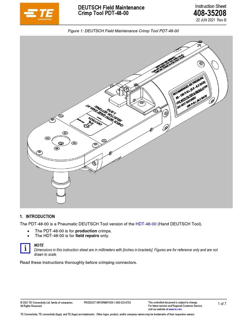
Crimping Heads 1-45216-0 and 1-45219-2 are
designed to crimp closed-end splices onto solid or
stranded copper wire size 22-10 AWG using Battery
Powered Double Action Hand Tool Kit 1213804-[ ] .
Refer to Figure 1 for tool components and Figure 2 for
Closed-End Splice product.
NOTE
i
The crimping heads can also be used with the 626
Double Action Pneumatic Tool Adapter 1213563-1.

This instruction sheet provides recommended
procedures for wire preparation, crimping head
installation, crimping, and maintenance and
inspection. For information concerning tool setup and
operation, refer to Customer Manual 409-10056
packaged with the battery tool kit.
NOTE
i
Dimensions are in metric units with [inches in
brackets]. Figures and illustrations are for
reference only and are not drawn to scale.
Reasons for reissue are provided in Section 7,
REVISION SUMMARY.
2. DESCRIPTION
The crimping head consists of integral jaws which
close in an arc-like motion. After an operator locates
the terminal or splice between the crimping jaws and
inserts the stripped wire, the tool is activated to crimp
the terminal or splice to the wire.
TOOL PART
NUMBER
ANDCOLOR
CODE
TOOL
MARKING
WIRE
SIZE
RANGE
(AWG)
PART NUMBER/
SPLICE TYPE COLOR
CODE SPLICE
TYPE
WIRE
COMBINATION
CHART
DOCUMENT
STRIP LENGTH
MIN. MAX.
1-45216-0 18-16
ECV-ECN 22-14
34304 Vinyl Red VS 408-1394
8.38 [.330] 9.14 [.360]
35115 NYLON Trans ECN 408-1271
36964 Vinyl Purple VS 408-1394
2-328375-3 Vinyl Purple VS 408-1394
1-45219-2 18-10
ECV-ECN 22-10 35653 NYLON Trans ECN 408-1021 10.67 [.420] 11.43 [.450]
36965 Vinyl Purple VS 408-1029
321519 Vinyl Purple ECV 408-1002 14.22 [.560] 16.00 [.630]
NOTE: In cases where twisting conductors for minimum loading is required, ensure that strip length is maintained after twisting.
408-10032
2of 4
Rev B
Figure 2
3. HEAD INSTALLATION AND REMOVAL
NOTE
i
Crimping heads are coated with a preservative to
prevent rust and corrosion. Wipe this preservative
from the head, particularly from the crimping
surfaces.
3.1. Installation
DANGER
STOP
To avoid personal injury, be sure to exercise
extreme caution when handling the crimp tool.
Avoid accidentally depressing the trigger control
when installing or removing crimp heads.

DANGER
STOP
DONOToperatethebatterytoolwithouttheproper
crimping head installed. After crimping head is
installed,makesurethatthequickpinsareproperly
insertedtoavoidpersonalinjuryanddamage to the
tool.
1. Remove quick pins from the adapter assembly.
Refer to Figure 1.
2. Insert crimping head into the adapter assembly.
3. After the crimping head is properly aligned, insert
the quick pins through the two holes in the adapter
and through the holes in the crimp head.
NOTE
i
The quick pins will "snap" into position when they
are properly inserted.

3.2. Removal
DANGER
STOP
To avoid personal injury, ALWAYS disconnect the
battery from the tool before removing crimping
head.
Remove the quick pins from the crimping head; then
remove the crimping head from the tool holder.
4. CRIMPING PROCEDURES
DANGER
STOP
To avoid personal injury, ALWAYS keep fingers
clear of crimping jaws when operating the tool.
Never place anything within the crimping jaws
except TE terminals or splices.
1. Strip wires to dimensions shown in Figure 2. DO
NOT nick wire strand or use wires with nicked or
missing conductor strands.
2. Insert stripped wires into the splice barrel.
3. Locate the splice with the wires inserted into the
crimping dies as shown in Figure 3. the skirt of the
ECN (Nylon) splice should nest against the splice
ejector. The ends of the ECV or VS (Vinyl) splices
should rest against the end of the locator.
Types
ECV and VS
Type ECN
End of Vinyl Closed-End
Splice Rests Against
Locator
Locator
Skirt of NYLON

Closed-End Splice
Rests Against Ejector
Figure 3
408-10032
3of 4
Rev B
4. Depress the trigger to advance the moving ram.
This closes the crimp jaws in order to hold the
terminal in place. DO NOT deform the wire barrel.
5. Activate the tool to complete the crimp. The crimp
tool automatically returns to the first position of the
cycle when the crimp is complete. Remove the
splice from the head.
6. Refer to Section 5 and Figures 4 and 5 for crimp
inspection.
CAUTION
!
Damaged product should not be used. If a
damagedspliceisevident, itshouldbecut from the
wire and replaced. Do NOT re-terminate splices.
5. MAINTENANCE AND INSPECTION
DANGER
STOP
To avoid personal injury, ALWAYS disconnect the
battery from the tool before performing
maintenance or inspection.
TE recommends that a maintenance and inspection
program be performed periodically to ensure
dependable and uniform terminations. The crimping
head should be inspected once a month. Frequency of
inspection should be adjusted to suit your
requirements through experience. Frequency of
inspection depends on:
•The care, amount of use, and handling of the
crimping head.
•The type and size of the product crimped.
•The degree of operator skill.
•The presence of abnormal amounts of dust and
dirt.
•Your own established standards.
Each crimping head is thoroughly inspected before
packaging. Since there is the possibility of crimping
head damage during shipment, new crimping heads
should be inspected immediately upon arrival at your
facility.
5.1. Daily Maintenance
TE recommends that each operator be responsible for
the following steps of daily maintenance:
1. Remove dust, moisture, and other contaminants
with a clean, soft brush, or a lint-free cloth. Do NOT
use objects that could damage the head.
2. Make sure that all pins, rings, and other
components are in place and secure.
DANGER
STOP
To avoid personal injury and damage to the tool,
make sure quick pins are properly inserted.
3. Make certain all surfaces are protected with a thin
coat of any good SAE 20 motor oil. Do NOT oil
excessively.
4. When the head assembly is not in use, store it in
a clean dry, area.
5.2. Periodic Inspection
Regular inspections should be performed by quality
control personnel. A record of scheduled inspections
should remain with the crimping heads or be supplied
to supervisory personnel responsible for the crimping
heads. Though recommendations call for at least one
inspection a month, the frequency should be based on
amount of use, working conditions, operator training
and skill, and your established company policies.
These inspections should include a visual inspection
(Paragraph 5.3) and a crimping chamber inspection
(Paragraph 5.5).
5.3. Visual Inspection
1. Remove all lubrication and accumulated film by
immersing the crimping head in a suitable
commercial degreaser that will not affect paint or
plastic.
2. Make certain all components are in place. If
replacements are necessary, contact TE.
3. Check all bearing surfaces for wear. Replace
worn parts.
4. Inspect crimp areas for flattened, chipped, or
broken parts.
5.4. Lubrication
Lubricate all pins, pivot points, and bearing surfaces
with a high quality grease. TE recommends the use of
MOLYKOTE† grease, which is a commercially
available lubricant. Lubricate according to the
following schedule:
Head used in daily production - lubricate daily
Head used daily (occasional) - lubricate weekly
Head used weekly - lubricate monthly
Wipe excess grease from crimping head, particularly
from jaw closure areas. Grease transferred from jaw
closure area onto certain terminations may affect the
electrical characteristics of an application.
† MOLYKOTE is a trademark.
408-10032
4of 4
Rev B
5.5. Gaging the Crimping Chamber
This inspection requires the use of plug gages
conforming to the dimensions shown in Figure 4. TE
does not manufacture or market these gages.
DANGER
STOP
Disconnect the battery and remove crimping head
from tool before inspecting crimping chambers.

1. Remove oil and dirt from the jaw bottoming
surfaces and plug gage element surfaces.
2. Close wire barrel crimping jaws until they are
bottomed, but not under pressure.
3. Align GO element with wire barrel crimping
section. Push element straight into crimping
chamber without using force. The GO element must
pass completely through the chamber as shown in
Figure 5.
4. Align the NO-GO element and try to insert it into
the chamber. The element may start entry, but it
must not pass completely through the crimping
chamber.
TOOL NUMBER GAGE ELEMENT DIAMETER
GO NO-GO
1-45216-0 2.311 - 2.319
[.0910 - .0913] 2.461 - 2.464
[.0969 - .0970]
1-45219-2 3.124 - 3.132
[.1230 - .1233] 3.274 - 3.277
[.1289 - .1290]
Figure 4
If the crimping chamber passes the gage inspection,
the crimping head is considered dimensionally correct
and should be lubricated with a THIN coat of any good
SAE 20 motor oil. If the crimping chamber does not
conform to the plug gage conditions, contact your local
TE representative or refer to Section 6,
REPLACEMENT AND REPAIR.
For additional information about the use of a plug
gage, see Instruction Sheet 408-7424.
Inspection of Crimping
Dies with Plug Gage JawsBottomedButNot
Under Pressure
GOmembermustpasscompletelythroughthecrimpingsurface.
NO-GO member may enter partially, but must not pass
completely through the length of the crimping surface.
Figure 5
6. REPLACEMENT AND REPAIR
Order replacement heads through your TE
representative, or call 1-800-526-5142, or send a
facsimile of your purchase order to 1-717-986-7605, or
write to:
CUSTOMER SERVICE (038-035)
TYCO ELECTRONICS CORPORATION
PO BOX 3608
HARRISBURG PA 17105-3608
For further repair and replacement information, call the
TE Tooling Assistance Center at the number at the
bottom of page 1.
7. REVISION SUMMARY
Revisions to this instruction sheet include:
•Changed company name and logo

This manual suits for next models

1

Other TE Connectivity Crimping Tools manuals

TE Connectivity 2063574-1 User manual

TE Connectivity

TE Connectivity 2063574-1 User manual

TE Connectivity CERTI- CRIMP Series User manual

TE Connectivity

TE Connectivity CERTI- CRIMP Series User manual

TE Connectivity ERGOCRIMP 539 664-2 User manual

TE Connectivity

TE Connectivity ERGOCRIMP 539 664-2 User manual

TE Connectivity 90084 User manual

TE Connectivity

TE Connectivity 90084 User manual

TE Connectivity PDT-48-00 User manual

TE Connectivity

TE Connectivity PDT-48-00 User manual

TE Connectivity PRO-CRIMPER III User manual

TE Connectivity

TE Connectivity PRO-CRIMPER III User manual

TE Connectivity SDE-SA 2391790-1 User manual

TE Connectivity

TE Connectivity SDE-SA 2391790-1 User manual

TE Connectivity 528050-3 User manual

TE Connectivity

TE Connectivity 528050-3 User manual

TE Connectivity 2391481-2 User manual

TE Connectivity

TE Connectivity 2391481-2 User manual

TE Connectivity 528008-4 User manual

TE Connectivity

TE Connectivity 528008-4 User manual

TE Connectivity 2393700-1 User manual

TE Connectivity

TE Connectivity 2393700-1 User manual

TE Connectivity SDE-SA PN 2063626-1 User manual

TE Connectivity

TE Connectivity SDE-SA PN 2063626-1 User manual

TE Connectivity ERGOCRIMP 539 748-2 User manual

TE Connectivity

TE Connectivity ERGOCRIMP 539 748-2 User manual

TE Connectivity CERTI-CRIMP 90165-1 User manual

TE Connectivity

TE Connectivity CERTI-CRIMP 90165-1 User manual

TE Connectivity 2063573-1 User manual

TE Connectivity

TE Connectivity 2063573-1 User manual

TE Connectivity 2217480 Series Reference guide

TE Connectivity

TE Connectivity 2217480 Series Reference guide

TE Connectivity 90260-1 User manual

TE Connectivity

TE Connectivity 90260-1 User manual

TE Connectivity 2386893-1 User manual

TE Connectivity

TE Connectivity 2386893-1 User manual

TE Connectivity SDE-SA User manual

TE Connectivity

TE Connectivity SDE-SA User manual

TE Connectivity 2844594-1 User manual

TE Connectivity

TE Connectivity 2844594-1 User manual

TE Connectivity IDC Hand tool RAST 2.5 User manual

TE Connectivity

TE Connectivity IDC Hand tool RAST 2.5 User manual

TE Connectivity 2063536-1 User manual

TE Connectivity

TE Connectivity 2063536-1 User manual

TE Connectivity 2063409-1 User manual

TE Connectivity

TE Connectivity 2063409-1 User manual

TE Connectivity ERGOCRIMP 5-1579001-1 User manual

TE Connectivity

TE Connectivity ERGOCRIMP 5-1579001-1 User manual

Popular Crimping Tools manuals by other brands

molex 207129 Series Specification sheet

molex

molex 207129 Series Specification sheet

molex 207129 Series specification

molex

molex 207129 Series specification

HARTING 09 99 000 0664 instructions

HARTING

HARTING 09 99 000 0664 instructions

molex 63823-7570 Specification sheet

molex

molex 63823-7570 Specification sheet

Tyco Electronics PRO-CRIMPER III instruction sheet

Tyco Electronics

Tyco Electronics PRO-CRIMPER III instruction sheet

Greenlee EK1550FLX Operation manual

Greenlee

Greenlee EK1550FLX Operation manual

Emerson klauke ESM 35CFM quick start guide

Emerson

Emerson klauke ESM 35CFM quick start guide

molex 63825-1670 Specification sheet

molex

molex 63825-1670 Specification sheet

KNIPEX 97 51 10 operating instructions

KNIPEX

KNIPEX 97 51 10 operating instructions

Textron Greenlee GATOR EK1230L230 Operation manual

Textron

Textron Greenlee GATOR EK1230L230 Operation manual

Viega PureFlow Product instructions

Viega

Viega PureFlow Product instructions

HRS HT102 instruction manual

HRS

HRS HT102 instruction manual

Greenlee GATOR EK628 instruction manual

Greenlee

Greenlee GATOR EK628 instruction manual

Textron Greenlee GATOR EK410LT Operation manual

Textron

Textron Greenlee GATOR EK410LT Operation manual

molex RHT-5771 Operating Instruction Sheet And Specifications

molex

molex RHT-5771 Operating Instruction Sheet And Specifications

JST BCT-8150 instruction manual

JST

JST BCT-8150 instruction manual

Emerson Klauke ESG 105RMCPCFB instructions

Emerson

Emerson Klauke ESG 105RMCPCFB instructions

Emerson Klauke UAP100120CFB manual

Emerson

Emerson Klauke UAP100120CFB manual

manuals.online logo
manuals.online logoBrands
  • About & Mission
  • Contact us
  • Privacy Policy
  • Terms and Conditions

Copyright 2025 Manuals.Online. All Rights Reserved.