408-7587
3of 4
Rev A
3. Actuate the machine a complete cycle. Check to
be sure the contact is properly crimped. The wire
must be visible through the inspection hole of the
contact.
4. INSPECTION
4.1. Daily Maintenance
The importance of daily maintenance cannot be over
emphasized, as this can easily and efficiently be
performed after each shift, ensuring satisfactory
performance and continuous production. TE
Connectivity recommends the following:
1. Remove dust, moisture, and other contaminants
with a clean brush or soft lint-free cloth. Do NOT
use objects that could damage the dies. If foreign
matter cannot be removed easily, or if the proper
replacement parts are not available, return the dies
to your supervisor.
2. Make sure the proper die holding screws are in
place and secured with the proper retaining rings.
3. Check die alignment and tighten die holding
screws at least twice daily. Make sure the dies are
protected with a THIN coat of any good S.A.E.
No. 20 motor oil. DO NOT OIL EXCESSIVELY.
4. When the dies are not in use, store them in a
clean, dry area.
4.2. Periodic Inspection
Regular inspections should be performed and
recorded by your Quality Control Department with a
record of scheduled inspections remaining with the
dies or supplied to supervisory personnel responsible
for the dies. TE recommends at least one inspection a
month, however, frequency of inspection will depend
on the amount of use, ambient working conditions,
operator training and skill, and your own established
standards. These inspections should be performed in
the following sequence.
A. Visual Inspection
1. Remove all lubrication and accumulated film by
immersing the dies in a suitable commercial de-
greaser that will not effect paint or plastic material.
2. Make sure all holding screws, retaining rings, and
die components are in place. Refer to the parts
listed in Figure 4 if replacements are necessary.
3. Check all bearing surfaces for wear. Remove and
replace worn components.
4. Inspect the crimp area for flattened, chipped,
cracked, worn, or broken areas. Make sure the
holding screws and the depressions on the
stationary die are properly color-coded. Refer to
Section 2, DESCRIPTION. If damage is evident, the
dies must be repaired before returning to service.
Refer to Section 5, REPAIR AND REPLACEMENT.
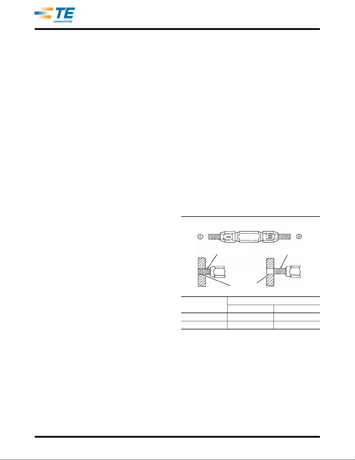
B. Mechanical Inspection
This inspection utilizes a GO / NO-GO gage
conforming to the dimensions in Figure 3. TE does not
manufacture or market these gages. Refer to
Instruction Sheet 408-7424.
Proceed as follows:
1. Mate the dies until it is evident that they have
bottomed. Hold the dies in this position with
approximately 69 kPa [10 psi].
2. Align the GO element with the wire barrel
crimping area and push it straight into the crimping
chamber without using force. The GO element must
pass completely through the crimping chamber as
shown in Figure 3.
3. Now align the NO-GO element and try to insert it
straight into the same crimping chamber. The
NO-GO element may start entry but must not pass
completely through as shown in Figure 3.
If the crimping chambers conform to the gage
inspection, the dies are considered dimensionally
correct and should be lubricated with a THIN coat of
oil. If not, the dies must be repaired before returning
them to service. Refer to Section 5, REPAIR AND
REPLACEMENT.
Figure 3
5. REPAIR AND REPLACEMENT
The parts listed in Figure 4 are customer replaceable
parts. A complete inventory can be stocked and
controlled to prevent lost time when replacement of
parts is necessary. The dies can also be returned to
TE for evaluation and repair. Send the dies and a
written description of the problem to:
CUSTOMER SERVICE (038-035)
TYCO ELECTRONICS CORPORATION
PO BOX 3608
HARRISBURG PA 17105-3608
CRIMPING DIE
NUMBER GAGE DIMENSION
GO (DIA) NO-TO (DIA)
90080-2 1.54 [.0605] 1.613 [.0635]
90103 1.003 [.0395] 1.080 [.0425]
Suggested Plug Gage Design
End View End View
GO Element NO-GO Element
WireBarrel
Crimping
Chamber