manuals.online logo
Brands
  1. Home
  2. •
  3. Brands
  4. •
  5. TE Connectivity
  6. •
  7. Crimping Tools
  8. •
  9. TE Connectivity 408-8569 User manual

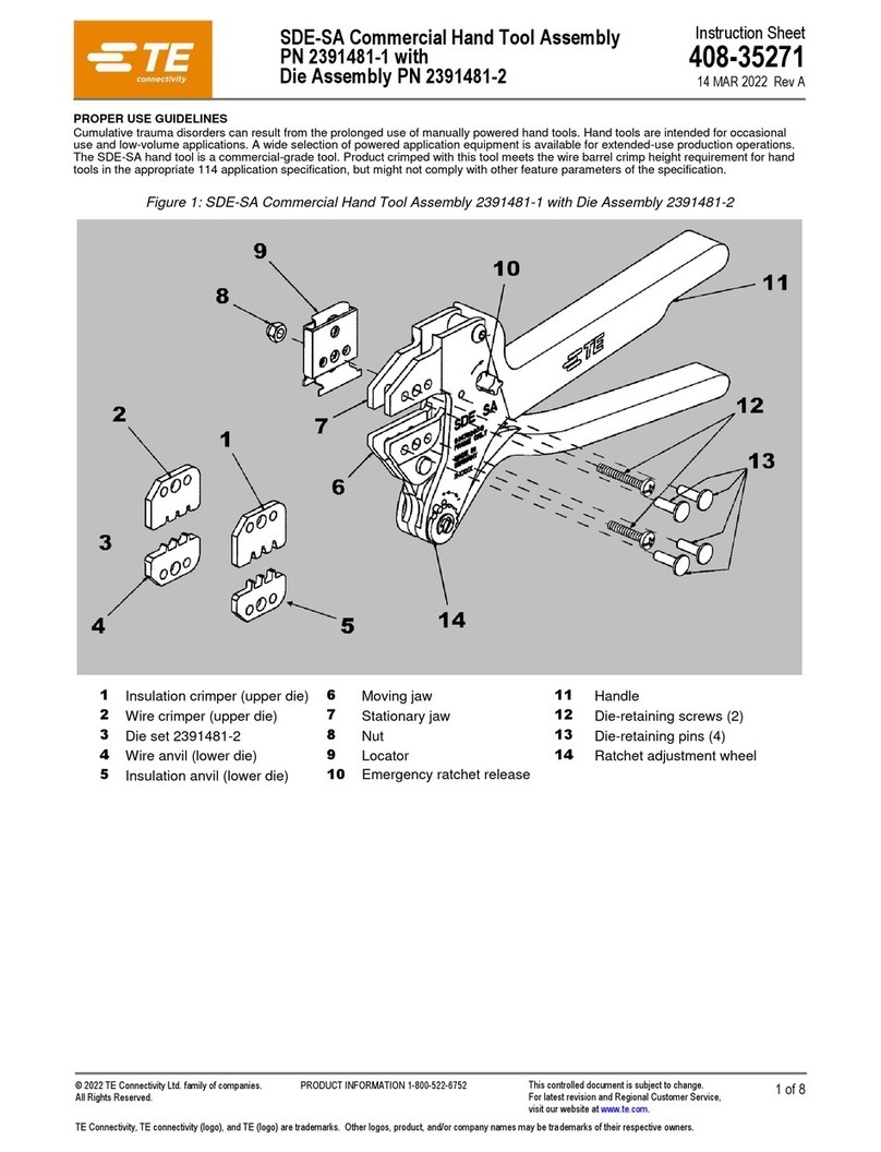
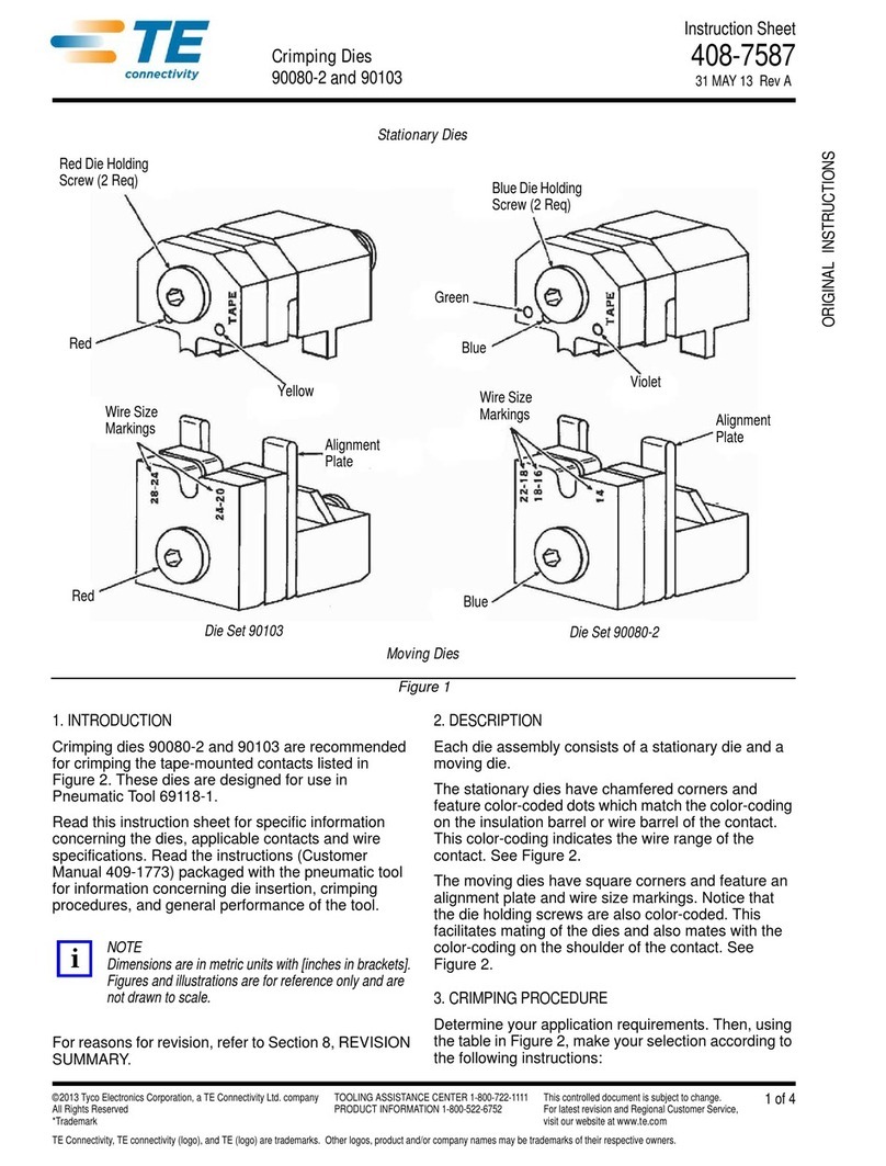
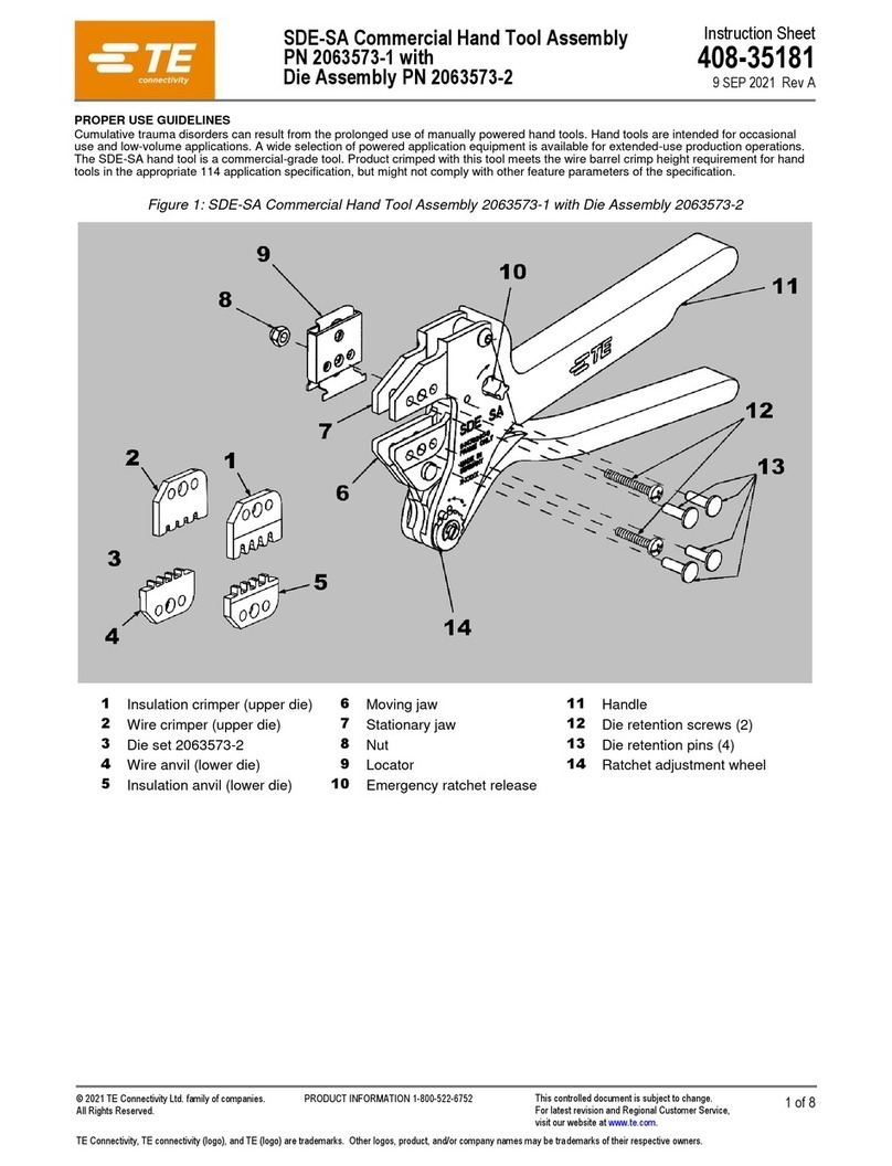
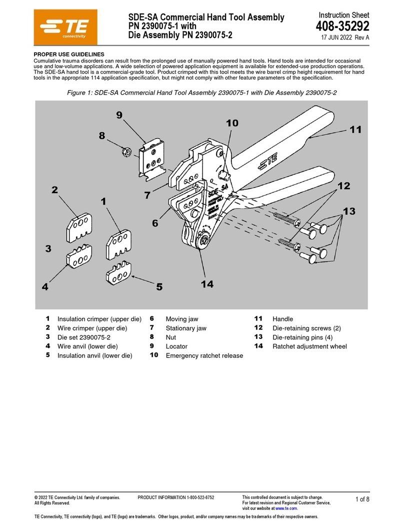
TE Connectivity 408-8569 User manual

©2012 Tyco Electronics Corporation, a TE Connectivity Ltd. company
All Rights Reserved
*Trademark
TE Connectivity, TE connectivity (logo), and TE (logo) are trademarks. Other logos, product and/or Company names may be trademarks of their respective owners.
1of 4
Instruction Sheet
TOOLING ASSISTANCE CENTER
1-800-722-1111
PRODUCT INFORMATION
1-800-522-6752
This controlled document is subject to change.
For latest revision and Regional Customer Service,
visit our website at www.te.com
408-8569
Connector-Specific Kit 1490479-1
for 0.64 mm [.025 in.]
Plug and Receptacle Connectors 26 MAR 12 Rev A
Figure 1
1. INTRODUCTION
This instruction sheet covers the installation and setup
procedures for Connector-Specific Kit 1490479-1. The
connector-specific kit is used in conjunction with Base
Assembly Universal Arbor Tool 768338-4 and Manual
Arbor Frame Assembly 91085-2 (see Figure 1), or
Pneumatic Auto-Cycle Unit 91112-3 to terminate
0.64 mm [.025 in.] Plug and Receptacle Connectors to
0.64 mm [.025 in.] centerline flat ribbon cable.
Refer to Instruction Sheets 408-7777 (supplied with
Manual Arbor Frame Assembly) and 408-6732
(supplied with Pneumatic Auto-Cycle Unit) for tooling
information. Installation and termination procedures
for the Base Assembly Universal Arbor Tool are
available in Instruction Sheet 408-4201.
Dimensions on this sheet are in millimeters
[followed by inches in brackets]. Figures and
illustrations are for reference only and are not
drawn to scale.
2. DESCRIPTION (Figure 1)
The connector-specific kit features a lower insert and
two locators. The lower insert and locators properly
align the connector for termination.
Lower Insert Locators
Connector-Specific Kit 1490479-1
Typical Application Tooling
Manual Arbor
FrameAssembly
91085-2 (Ref)
Base Assembly
UniversalArbor Tool
768338-4 (Ref)
FrontGuard
(Ref)
NOTE
i
ORIGINAL INSTRUCTIONS
408-8569
2of 4
Rev A
Figure 2
3. INSTALLATION AND SETUP OF
CONNECTOR -SPECIFIC KIT
3.1. Installation
These procedures are typical for the manual arbor
frame assembly and the pneumatic auto-cycle unit.
1. Loosen the two socket head cap screws that
secure the locators onto the lower insert.
2. Place the connector between the locators and
slide the locators against the connector; then
secure the locators by fully tightening the socket
head cap screws.
Depending on which style connector is being
terminated the connector will rest on either the
mating face of the connector on the bottom of the
slot that is in the lower insert; or the shoulders of
the connectors will rest on the step of the lower
insert, as shown in Figure 3.
When locating the connector in the lower insert be
sure to center the connector as much as possible.
3. When the locators are secure, remove the
connector from the lower insert.
4. Remove the screw that secures the adjustment
block to the universal arbor tool then remove the
adjustment block. Slide the lower insert onto the
base assembly until it is against the compression
spring. See Figure 2.
5. Re-assemble the adjustment block. Make sure to
orient the block so that the fine adjustment screw is
closest to the right side and bottom side of the
block. See detail in Figure 2.
To avoid improper terminations, the adjustment
block must be re-assembled properly.
6. Loosen the fine adjustment screw so that it is not
touching the lower insert.
7. Install the Base Assembly Universal Arbor Tool
onto the frame assembly, as described in 408-4201.
To avoid personal injury, be sure to disconnect the
air from the main air valve when using Pneumatic
Auto-Cycle Unit 91112-3.
3.2. Setup
1. Remove the cover from the connector and place
the connector into the lower insert as described in
Paragraph 3.1.
Universal Arbor
Tool (Ref)
Compression
Spring
Socket Head
Cap Screws
Arbor Frame
Assembly (Ref)
Adjustment
Block
Screw
Detail Fine Adjustment
Screw
NOTE: Guards not shown for clarity. (See Detail)
Locators
Lower
Insert
NOTE
i
!
CAUTION
!
CAUTION
DANGER
STOP
408-8569
3of 4
Rev A
Figure 3
2. Position the cable onto the universal arbor tool
and follow termination procedures according to the
instructions packaged with the Base Assembly
Universal Arbor Tool, Instruction Sheet 408-4201.
3.3. Connector Inspection
1. Perform a test termination and inspect the
connector to ensure that the cable conductors are
aligned with the contacts. If available, use a tester to
inspect the termination, or remove the connector
cover and inspect the termination with a microscope
to ensure that the cable conductors are properly
aligned with the contacts. Refer to applicable
application specification (114-series) for termination
height dimensions.
2. If the cable conductors are not aligned with the
contacts, a re-alignment of the connector is
necessary. Determine the direction the connector
must be moved to align the cable conductors with
the contacts. Loosen the two locking setscrews on
the universal arbor tool (which secure the lower
insert) and re-align the lower insert.
For additional information on connector and cable
alignment, refer to the instructions packaged with
the universal arbor tool.
4. CONNECTOR-SPECIFIC KIT INSPECTION
The connector-specific kit has been inspected and
should be verified with the information provided in
Figure 4. It is recommended that the kit be inspected
immediately upon its arrival at your facility (and at
regularly scheduled intervals) to ensure that the kit
components have not been damaged during handling.
For additional information concerning connector-
specific kits, or to purchase additional kits, contact
your local TE Connectivity Representative or:
CUSTOMER SERVICE (038-035)
TYCO ELECTRONICS CORPORATION
PO BOX 3608
HARRISBURG PA 17105-3608
5. REVISION SUMMARY
•New logo
AllPlastic PlugConnector
390377-[ ] (Ref) Metal Shell Receptacle
Connector 390399-[ ] (Ref)
Cable
Lower Insert 1490477-1
Connector Rests
on Mating Face
Connector Rests
on Shoulder
NOTE
i
408-8569
4of 4
Rev A
Figure 4
2
3
1
100.08 [3.940]
20.57 [.810] 4.57 ±0.13 [.180 ±.005]
7.29 +0/-0.13
[.287 +.000/-.005]
13.72 ±0.25
[.540 ±.010]
21.74 +0/-0.25
[.856 +.000/-.010]
REPLACEABLE PARTS
ITEM PART NUMBER DESCRIPTION QTY PER KIT
1 1490477-1 LOWER INSERT 1
2 1490478-1 LOCATOR 2
3 1-21000-4 SCREW, Socket Head Cap, 4-40 x .38 in. L 2

Other TE Connectivity Crimping Tools manuals

TE Connectivity 2378724-1 User manual

TE Connectivity

TE Connectivity 2378724-1 User manual

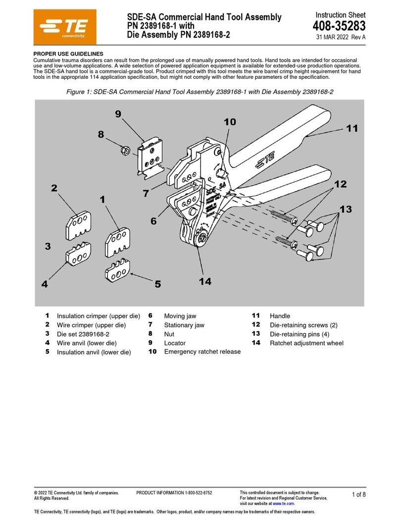
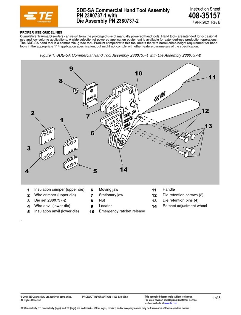
TE Connectivity SDE-SA User manual

TE Connectivity

TE Connectivity SDE-SA User manual
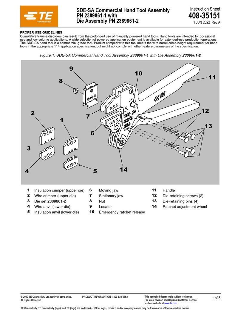
TE Connectivity PRO-CRIMPER III User manual
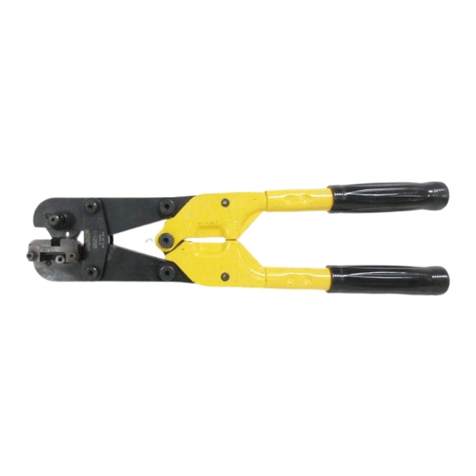
TE Connectivity

TE Connectivity PRO-CRIMPER III User manual

TE Connectivity 58422-1 User manual

TE Connectivity

TE Connectivity 58422-1 User manual

TE Connectivity AT-65 User manual

TE Connectivity

TE Connectivity AT-65 User manual

TE Connectivity 2381454-1 Instruction Manual

TE Connectivity

TE Connectivity 2381454-1 Instruction Manual

TE Connectivity CERTI-CRIMP 90066-7 User manual

TE Connectivity

TE Connectivity CERTI-CRIMP 90066-7 User manual

TE Connectivity 2407132-1 User manual

TE Connectivity

TE Connectivity 2407132-1 User manual

TE Connectivity ERGOCRIMP 4-1579001-6 User manual

TE Connectivity

TE Connectivity ERGOCRIMP 4-1579001-6 User manual

TE Connectivity 2391789-1 User manual

TE Connectivity

TE Connectivity 2391789-1 User manual

TE Connectivity 69069 User manual

TE Connectivity

TE Connectivity 69069 User manual

TE Connectivity SDE-SA User manual

TE Connectivity

TE Connectivity SDE-SA User manual

TE Connectivity PRO-CRIMPER III User manual

TE Connectivity

TE Connectivity PRO-CRIMPER III User manual

TE Connectivity 2372541-1 User manual

TE Connectivity

TE Connectivity 2372541-1 User manual

TE Connectivity 90080-2 User manual

TE Connectivity

TE Connectivity 90080-2 User manual

TE Connectivity 58075-1 User manual

TE Connectivity

TE Connectivity 58075-1 User manual

TE Connectivity 1-45216-0 User manual

TE Connectivity

TE Connectivity 1-45216-0 User manual

TE Connectivity CERTI-CRIMP II User manual

TE Connectivity

TE Connectivity CERTI-CRIMP II User manual

TE Connectivity SDE-SA User manual

TE Connectivity

TE Connectivity SDE-SA User manual
TE Connectivity COPALUM 408-2281 User manual

TE Connectivity

TE Connectivity COPALUM 408-2281 User manual

TE Connectivity PRO-CRIMPER III User manual

TE Connectivity

TE Connectivity PRO-CRIMPER III User manual

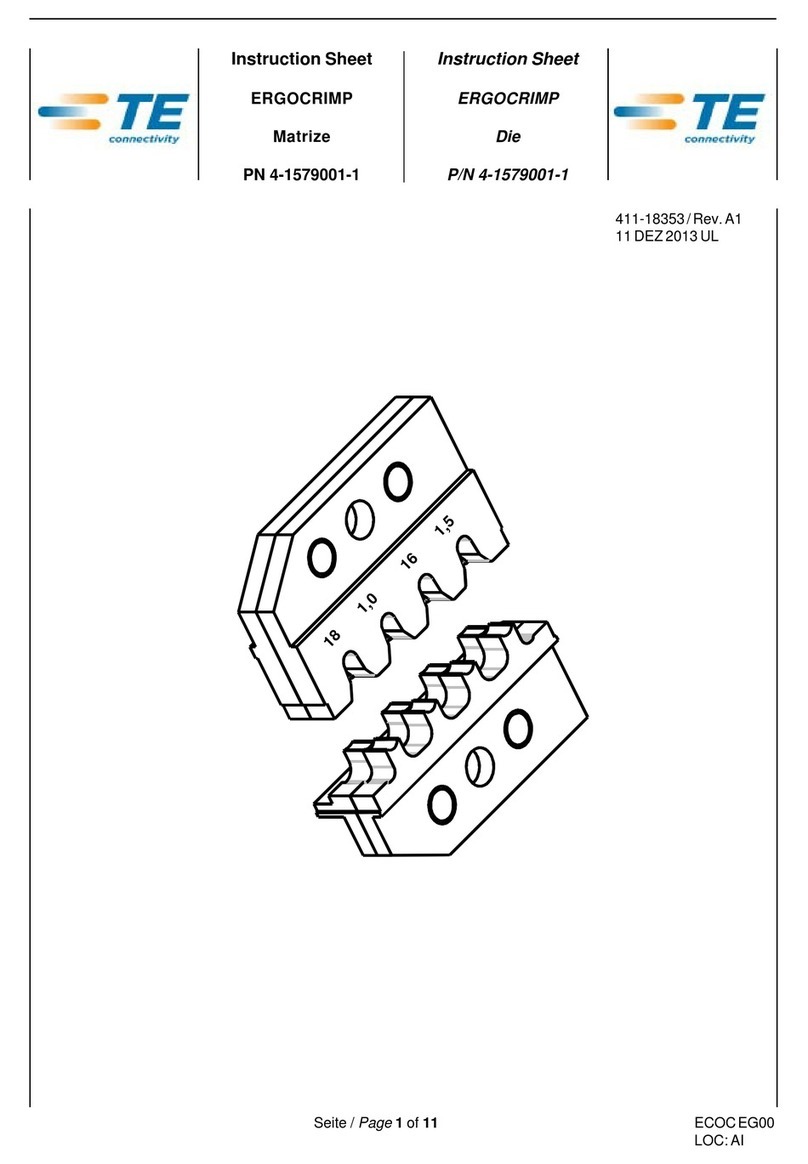
TE Connectivity ERGOCRIMP 4-1579001-1 User manual

TE Connectivity

TE Connectivity ERGOCRIMP 4-1579001-1 User manual

TE Connectivity 2359761-1 User manual

TE Connectivity

TE Connectivity 2359761-1 User manual

TE Connectivity CERTI- CRIMP Series User manual

TE Connectivity

TE Connectivity CERTI- CRIMP Series User manual

Popular Crimping Tools manuals by other brands

Danfoss ET4350 Operator's manual

Danfoss

Danfoss ET4350 Operator's manual

Milwaukee M18 Operator's manual

Milwaukee

Milwaukee M18 Operator's manual

Textron ESG105L instruction manual

Textron

Textron ESG105L instruction manual

molex MTA-100 Setup instructions

molex

molex MTA-100 Setup instructions

Textron Greenlee GATOR EK1240KLX Operation manual

Textron

Textron Greenlee GATOR EK1240KLX Operation manual

Glomar Dr. Peters EKS-3-PRO instruction manual

Glomar

Glomar Dr. Peters EKS-3-PRO instruction manual

Tyco Electronics PRO-CRIMPER III instruction sheet

Tyco Electronics

Tyco Electronics PRO-CRIMPER III instruction sheet

Rennsteig PEW 8.75 operating instructions

Rennsteig

Rennsteig PEW 8.75 operating instructions

molex 63825-1670 Specification sheet

molex

molex 63825-1670 Specification sheet

Aalberts industries Apollo PEX 69PTKH00143 instruction sheet

Aalberts industries

Aalberts industries Apollo PEX 69PTKH00143 instruction sheet

molex Perma-Seal 64005-4500 manual

molex

molex Perma-Seal 64005-4500 manual

molex 207129 Series Specification sheet

molex

molex 207129 Series Specification sheet

Hubbell BURNDY PATRIOT 81K2 Series SAFETY OPERATING & MAINTENANCE INSTRUCTIONS

Hubbell

Hubbell BURNDY PATRIOT 81K2 Series SAFETY OPERATING & MAINTENANCE INSTRUCTIONS

Tyco Electronics 58649-1 instruction sheet

Tyco Electronics

Tyco Electronics 58649-1 instruction sheet

molex 63825-5000 Specification sheet

molex

molex 63825-5000 Specification sheet

molex 63825-9670 Specification sheet

molex

molex 63825-9670 Specification sheet

molex 63811-7000 Specification sheet

molex

molex 63811-7000 Specification sheet

molex 63811-5100 Specification sheet

molex

molex 63811-5100 Specification sheet

manuals.online logo
manuals.online logoBrands
  • About & Mission
  • Contact us
  • Privacy Policy
  • Terms and Conditions

Copyright 2025 Manuals.Online. All Rights Reserved.