manuals.online logo
Brands
  1. Home
  2. •
  3. Brands
  4. •
  5. TE Connectivity
  6. •
  7. Crimping Tools
  8. •
  9. TE Connectivity PRO-CRIMPER III User manual

TE Connectivity PRO-CRIMPER III User manual

Instruction Sheet
PRO- CRIMPER* III Hand Crimping 408--9140
LOC B
1of 3
E2011 Tyco Electronics Corporation, a TE Connectivity Ltd. Company
All Rights Reserved
*Trademark
TE Connectivity, TE connectivity (logo), and TE (logo) are trademarks. Other logos, product and/or Company names may be trademarks of their respective owners.
TOOLI NG ASSISTANCE CENTER 1--800--722 -- 1111
PRODUCT INFORMATION 1--800--522--6752
This controlled document is subject to change.
For latest revision and Regional Customer Service,
visit our website at www.te.com
20 APR 11 Rev DTool Assembly 58433- 1
PROPER USE GUIDELINES
Cumulative Trauma Disorders can result from the prolonged use of manually powered hand tools. Hand tools are intended for occasional use and low volume
applications. A wide selection of powered application equipment for extended--use, production operations is available.
Figure 1
Die Assembly
58435--1
(Replaceable Item)
Crimp Section
Identification
Numbers
Ratchet
Adjustment
Wheel
Screw
Pivot Pin
Refer to Catalog 82074
For Applicable Connectors
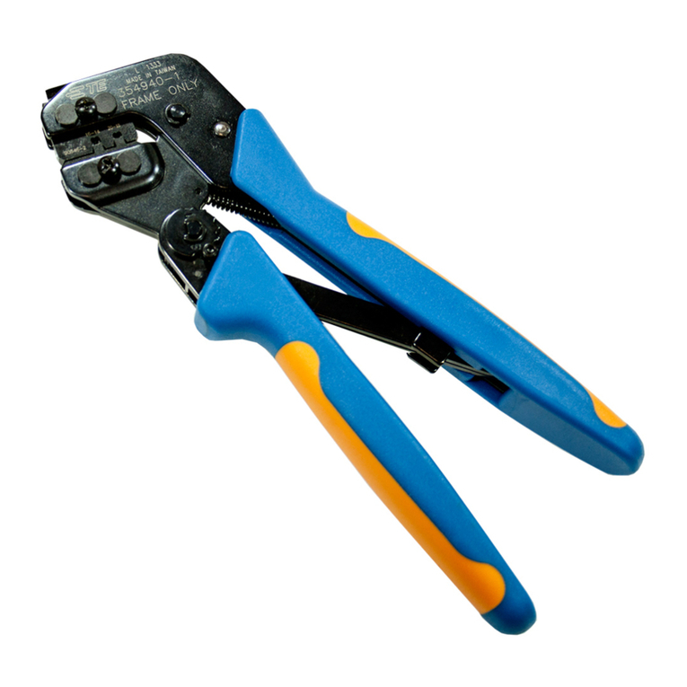
PRO--CRIMPER III
Hand Tool Frame
Assembly 354940--1
(408--9930)
1. INTRODUCTION
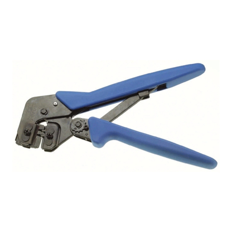
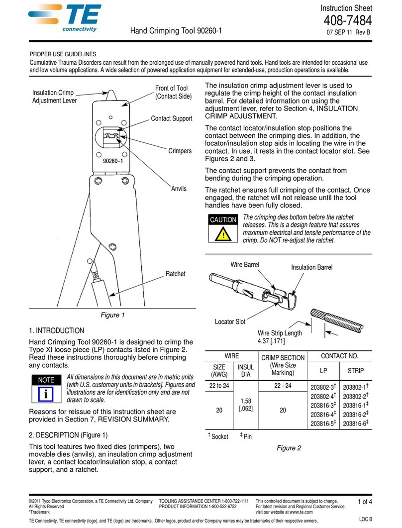
PRO--CRIMPER III Hand Crimping Tool 58433--1
(Figure 1) is designed to crimp 50--Ohm Commercial
BNC and TNC plugs and jacks onto RG 58/U, RG
59/U, and RG 62/U cable.
Reasons for reissue of this sheet are provided in
Section 6, REVISION SUMMARY.
2. DESCRIPTION (Figure 1)
The tool features a replaceable die assembly
(58435--1) with two ferrule crimp sections and two
center contact crimp sections. The crimp sections are
marked to identify the cable sizes used with the
connectors as follows:
SRG 58/U crimp sections (center contact and
ferrule) are identified by the number “58”
located below the crimp section.
SRG 59/U and 62/U crimp sections (center
contact and ferrule) are identified by the
number “59” located below the crimp section.
3. CRIMPING PROCEDURE (Figure 2)
3.1. Center Contact
1. Slide the ferrule onto the cable, then strip the
cable according to the dimensions in the
appropriate connector instruction sheet.
2. Slide the center contact onto the center
conductor of the cable; then insert the contact
assembly into the contact crimp section of the dies.
Make sure that the flange on the end of the
center contact butts against the crimping die. See
Figure 3.
3. Crimp the center contact by holding the contact
and cable in place; then close the tool handles until
the ratchet releases.
4. Remove the crimped center contact.
ORIGINAL INSTRUCTIONS
NOTE
i
408- 9140
Rev D2of 3
Figure 2
Insert Center
Contact into
the Partially Closed
Crimping Dies
Ferrule
(Ref)
Center Contact
Slipped Over the
Center Conductor
Flange on End of
Center that Butts
Against the Die
Flange on the
End of the
Contact
Crimping Die
Figure 3
3.2. Ferrule
1. Insert the crimped center contact into the
connector body until the cable dielectric butts
against the dielectric inside the connector body.
The flared braid will then fit around the support
sleeve of the connector body.
2. Slide the ferrule forward over the braid until the
ferrule butts against the shoulder on the connector
body.
3. Place the ferrule on the approriate anvil of the
die assembly so that the shoulder on the connector
body butts against the die. See Figure 4.
4. Holding the assembly in place, close the tool
handles until the ratchet releases.
5. Remove the crimped assembly.
4. INSPECTION
4.1. Visual Inspection
Inspection of the crimping dies should be made on a
regular basis to ensure that they have not become
worn or damaged. Inspect the crimp sections for
flattened, chipped, worn, or broken areas. If damage
or abnormal wear is evident, the dies must be
replaced. Refer to Section 5, PARTS
REPLACEMENT.
4.2. Measuring Die Opening
The die assembly will perform correctly as long as:
a. the product specified is correct for the
application,
b. the specific die assembly is used,
c. the die assembly has been measured to
ensure that the openings are correct, and
d. the tool has been adjusted correctly.
Figure 5 provides information on die opening sizes.
Figure 4
Crimping Ferrule
Shoulder On
Connector Body
Butts Against Die
Ferrule On
Anvil Of
Crimping Die
Typical RF
Connector (Ref)
Crimping
Die (Ref)
408- 9140
3of 3Rev D
4.3. Ratchet Adjustment
The ratchet mechanism features an adjustment wheel
with eight settings. The adjustment wheel controls the
amount of handle pressure exerted on the tool jaws
and crimping dies during crimping. If the crimp is not
acceptable, adjust the ratchet as follows:
1. Sufficiently loosen the screw at the ratchet
adjustment wheel so that the wheel can be rotated
above the post that engages the teeth in the wheel.
2. If the crimp is too loose, turn the wheel to a
higher notch (for example, if the wheel is set at
notch no. 5, move the wheel to notch no. 6). If the
crimp is too tight, move the wheel to a lower notch.
3. Tighten the screw at the ratchet adjustment
wheel.
If the crimp cannot be made to conform to the
dimensions provided in the appropriate product
application specification, the tool and/or dies are
defective and must be replaced.
Other dies of the PRO--CRIMPER III Series Hand
Criming Tool may be used in this tool; however,
the ratchet adjustment wheel may require
adjustment to achieve acceptable crimp height.
5. PARTS REPLACEMENT
Customer--replaceable parts are shown in Figure 1.
Available separately, PRO--CRIMPER III Repair Kit
679221--1 includes a variety of pins, rings, screws,
and springs. If the dies are damaged or worn
excessively, they must be replaced. Order the repair
kit and replaceable parts through your TE
Connectivity Representative, or call
1--800--526--5142, or send a facsimile of your
purchase order to 1--717--986--7605, or write to:
Customer Service (38--35)
Tyco Electronics Corporation
P.O. Box 3608
Harrisburg, PA 17105--3608
6. REVISION SUMMARY
SUpdated document to corporate requirements
SNew logo
Figure 5
5.28 mm + .10
[.208 in. + .004]
6.10 mm + .10
[.240 in. + .004]
.043 in. +.003
--.001
1.09 mm +.08
-- . 0 3
.050 in. +.003
--.002
1.27 mm +.08
-- . 0 5
NOTE
i

Other manuals for PRO-CRIMPER III

17

This manual suits for next models

1

Other TE Connectivity Crimping Tools manuals
TE Connectivity PRO-CRIMPER III User manual
TE Connectivity

TE Connectivity PRO-CRIMPER III User manual

TE Connectivity AMP 3K Reference guide

TE Connectivity

TE Connectivity AMP 3K Reference guide

TE Connectivity 2395308-1 User manual

TE Connectivity

TE Connectivity 2395308-1 User manual

TE Connectivity SDE User manual

TE Connectivity

TE Connectivity SDE User manual

TE Connectivity PRO-CRIMPER III User manual

TE Connectivity

TE Connectivity PRO-CRIMPER III User manual

TE Connectivity SDE-SA User manual

TE Connectivity

TE Connectivity SDE-SA User manual

TE Connectivity PRO-CRIMPER III User manual

TE Connectivity

TE Connectivity PRO-CRIMPER III User manual

TE Connectivity 2063574-1 User manual

TE Connectivity

TE Connectivity 2063574-1 User manual

TE Connectivity ERGOCRIMP 539 664-2 User manual

TE Connectivity

TE Connectivity ERGOCRIMP 539 664-2 User manual

TE Connectivity TETRA-CRIMP 59824-1 User manual

TE Connectivity

TE Connectivity TETRA-CRIMP 59824-1 User manual

TE Connectivity SDE-SA User manual

TE Connectivity

TE Connectivity SDE-SA User manual

TE Connectivity 2063567-1 User manual

TE Connectivity

TE Connectivity 2063567-1 User manual

TE Connectivity 2390409-1 User manual

TE Connectivity

TE Connectivity 2390409-1 User manual

TE Connectivity 2378724-1 User manual

TE Connectivity

TE Connectivity 2378724-1 User manual

TE Connectivity SDE-SA User manual

TE Connectivity

TE Connectivity SDE-SA User manual

TE Connectivity 1213890-1 Reference guide

TE Connectivity

TE Connectivity 1213890-1 Reference guide

TE Connectivity 2368740-1 User manual

TE Connectivity

TE Connectivity 2368740-1 User manual

TE Connectivity 58079-3 User manual

TE Connectivity

TE Connectivity 58079-3 User manual

TE Connectivity 2379381-1 User manual

TE Connectivity

TE Connectivity 2379381-1 User manual

TE Connectivity IDC Hand tool RAST 2.5 User manual

TE Connectivity

TE Connectivity IDC Hand tool RAST 2.5 User manual

TE Connectivity PRO- CRIMPER III User manual

TE Connectivity

TE Connectivity PRO- CRIMPER III User manual

TE Connectivity 528008-4 User manual

TE Connectivity

TE Connectivity 528008-4 User manual

TE Connectivity SDE-SA 2389861-1 User manual

TE Connectivity

TE Connectivity SDE-SA 2389861-1 User manual

TE Connectivity 2390882-1 User manual

TE Connectivity

TE Connectivity 2390882-1 User manual

Popular Crimping Tools manuals by other brands

molex 63823-6470 Specification sheet

molex

molex 63823-6470 Specification sheet

Tyco Electronics PRO-CRIMPER III instruction sheet

Tyco Electronics

Tyco Electronics PRO-CRIMPER III instruction sheet

Panduit PAT4.0 Series quick guide

Panduit

Panduit PAT4.0 Series quick guide

Emerson Klauke EK 120UCFB manual

Emerson

Emerson Klauke EK 120UCFB manual

Cembre B1350-C Operation and maintenance manual

Cembre

Cembre B1350-C Operation and maintenance manual

Emerson Klauke MAPAX325CFM manual

Emerson

Emerson Klauke MAPAX325CFM manual

Danfoss ET4350 Operator's manual

Danfoss

Danfoss ET4350 Operator's manual

molex 207129 Series Specification sheet

molex

molex 207129 Series Specification sheet
molex 207129 Series specification

molex

molex 207129 Series specification

molex RHT 2761-CC Operating Instruction Sheet And Specifications

molex

molex RHT 2761-CC Operating Instruction Sheet And Specifications

HARTING 09 99 000 0664 instructions

HARTING

HARTING 09 99 000 0664 instructions

Staubli M-PZ-T2600 operating instructions

Staubli

Staubli M-PZ-T2600 operating instructions

HARTING 09 99 000 0119 Operation manual

HARTING

HARTING 09 99 000 0119 Operation manual

Limora 532167 quick start guide

Limora

Limora 532167 quick start guide

Rennsteig PEW15 owner's manual

Rennsteig

Rennsteig PEW15 owner's manual

Textron Klauke ERB0818-L instruction manual

Textron

Textron Klauke ERB0818-L instruction manual

Panduit MSPT-1.3 quick start guide

Panduit

Panduit MSPT-1.3 quick start guide

Temper Koban KCM-400 instruction manual

Temper

Temper Koban KCM-400 instruction manual

manuals.online logo
manuals.online logoBrands
  • About & Mission
  • Contact us
  • Privacy Policy
  • Terms and Conditions

Copyright 2025 Manuals.Online. All Rights Reserved.