manuals.online logo
Brands
  1. Home
  2. •
  3. Brands
  4. •
  5. TE Connectivity
  6. •
  7. Crimping Tools
  8. •
  9. TE Connectivity 58046-1 User manual

TE Connectivity 58046-1 User manual

Other TE Connectivity Crimping Tools manuals

TE Connectivity 528050-3 User manual

TE Connectivity

TE Connectivity 528050-3 User manual

TE Connectivity 2844594-1 User manual

TE Connectivity

TE Connectivity 2844594-1 User manual

TE Connectivity 2063530-1 User manual

TE Connectivity

TE Connectivity 2063530-1 User manual

TE Connectivity ERGOCRIMP 539 723-2 User manual

TE Connectivity

TE Connectivity ERGOCRIMP 539 723-2 User manual

TE Connectivity 1752786-1 User manual

TE Connectivity

TE Connectivity 1752786-1 User manual

TE Connectivity SDE-SA User manual

TE Connectivity

TE Connectivity SDE-SA User manual

TE Connectivity SDE-SA User manual

TE Connectivity

TE Connectivity SDE-SA User manual

TE Connectivity 825508-5 User manual

TE Connectivity

TE Connectivity 825508-5 User manual

TE Connectivity 2391789-1 User manual

TE Connectivity

TE Connectivity 2391789-1 User manual

TE Connectivity AMP 3K Reference guide

TE Connectivity

TE Connectivity AMP 3K Reference guide

TE Connectivity PRO-CRIMPER III 2161732-1 User manual

TE Connectivity

TE Connectivity PRO-CRIMPER III 2161732-1 User manual

TE Connectivity 2063573-1 User manual

TE Connectivity

TE Connectivity 2063573-1 User manual

TE Connectivity PRO-CRIMPER III User manual

TE Connectivity

TE Connectivity PRO-CRIMPER III User manual

TE Connectivity Faston Series User manual

TE Connectivity

TE Connectivity Faston Series User manual

TE Connectivity 1213875 Series User manual

TE Connectivity

TE Connectivity 1213875 Series User manual

TE Connectivity AMP 5k/40 CE User manual

TE Connectivity

TE Connectivity AMP 5k/40 CE User manual

TE Connectivity PRO-CRIMPER III User manual

TE Connectivity

TE Connectivity PRO-CRIMPER III User manual

TE Connectivity 2394165-1 User manual

TE Connectivity

TE Connectivity 2394165-1 User manual

TE Connectivity 91366- 1 User manual

TE Connectivity

TE Connectivity 91366- 1 User manual

TE Connectivity SDE-SA User manual

TE Connectivity

TE Connectivity SDE-SA User manual

TE Connectivity PRO-CRIMPER III User manual

TE Connectivity

TE Connectivity PRO-CRIMPER III User manual

TE Connectivity SOLISTRAND 69097 User manual

TE Connectivity

TE Connectivity SOLISTRAND 69097 User manual

TE Connectivity ERGOCRIMP 0-1579001-6 User manual

TE Connectivity

TE Connectivity ERGOCRIMP 0-1579001-6 User manual

TE Connectivity SDE-SA User manual

TE Connectivity

TE Connectivity SDE-SA User manual

Popular Crimping Tools manuals by other brands

molex 63825-3000 Specification sheet

molex

molex 63825-3000 Specification sheet

Elpress PVX611 manual

Elpress

Elpress PVX611 manual

Tyco Electronics 69156-1 instruction sheet

Tyco Electronics

Tyco Electronics 69156-1 instruction sheet

CRH CRL CBLHCT1 instruction manual

CRH

CRH CRL CBLHCT1 instruction manual

Emerson Klauke MAPAX325CFM manual

Emerson

Emerson Klauke MAPAX325CFM manual

Emerson Klauke ES 105CFM manual

Emerson

Emerson Klauke ES 105CFM manual

KIMBALL MIDWEST 27-798 Operating instructions manual

KIMBALL MIDWEST

KIMBALL MIDWEST 27-798 Operating instructions manual

BGB 295060 Operation guide

BGB

BGB 295060 Operation guide

Danfoss ET4350 Operator's manual

Danfoss

Danfoss ET4350 Operator's manual

Milwaukee M18 Operator's manual

Milwaukee

Milwaukee M18 Operator's manual

HOGERT HT1P169 user manual

HOGERT

HOGERT HT1P169 user manual

Textron ESG105L instruction manual

Textron

Textron ESG105L instruction manual

Tyco Electronics 90035-3 instruction sheet

Tyco Electronics

Tyco Electronics 90035-3 instruction sheet

Emerson Klauke ES 20RMCCFB manual

Emerson

Emerson Klauke ES 20RMCCFB manual

Continental Refrigerator PC150HD quick start guide

Continental Refrigerator

Continental Refrigerator PC150HD quick start guide

Tyco Electronics CERTI-CRIMP 90418-1 instruction sheet

Tyco Electronics

Tyco Electronics CERTI-CRIMP 90418-1 instruction sheet

Emerson Klauke ES 105CFB manual

Emerson

Emerson Klauke ES 105CFB manual

molex 207129 Series Specification sheet

molex

molex 207129 Series Specification sheet

manuals.online logo
manuals.online logoBrands
  • About & Mission
  • Contact us
  • Privacy Policy
  • Terms and Conditions

Copyright 2025 Manuals.Online. All Rights Reserved.

Indenter Die
(Stationary)
Ferrule
Crimp
Sections
Anvil Die
(Moving)
Center
Contact
Locator
Center
Contact
Crimp
Section
©2011 Tyco Electronics Corporation, a TE Connectivity Ltd. Company
All Rights Reserved
*Trademark
TE Connectivity, TE connectivity (logo), and TE (logo) are trademarks. Other logos, product and/or Company names may be trademarks of their respective owners.
1of 4
Instruction Sheet
TOOLING ASSISTANCE CENTER
1-800-722-1111

PRODUCT INFORMATION
1-800-522-6752
This controlled document is subject to change.
For latest revision and Regional Customer Service,
visit our website at www.te.com LOC B
408-6759


Crimping Die Assembly 58046-1 27 JUN 11 Rev C
PROPER USE GUIDELINES
Cumulative Trauma Disorders can result from the prolonged use of manually powered hand tools. Hand tools are intended for occasional use
and low volume applications. A wide selection of powered application equipment for extended-use, production operations is available.
Figure 1
1. INTRODUCTION
This instruction sheet covers theuse and maintenance
of Crimping Die Assembly 58046-1, which is used in
PRO-CRIMPER* III Hand Tool Frame Assembly
354940-1. The die assembly crimps various
configurations of Commercial SMB Connectors onto
coaxial cable.
Figure 2
Tool Jaws
(Ref)
Die
Assembly
Die
Retaining
Screws
PRO-CRIMPER III
Hand tool Frame
Assembly 354940-1
Catalog 82074 provides a guide for cable-to-
connector selection. For cable sizes and connectors
not referenced in the catalog, contact Product
Engineering for connector recommendations.
NOTE
i
All dimensions on this document are in metric units
[with U.S. customary units in brackets].


Reasons for reissue are provided in Section 7,
REVISION SUMMARY.
2. DESCRIPTION (FIGURE 1)
Each die assembly consists of an indenter die and an
anvil die, and includes a center-contact crimp section
and a center-contact locator. The die assembly
features two large crimp sections for ferrules.
3. DIE INSTALLATION
1. Close the tool handles until the ratchet releases,
then allow the handles to open fully.
2. Insert the dies into the tool jaws as shown in
Figure 2, and align the retaining holes in each die
with the associated holes in the tool frame.
3. Thread, but do not tighten, the die retaining
screws into the holes.
408-6759
2of 4
Rev C
4. Carefully close the tool handles, making sure that
the dies align properly.
5. Tighten the die retaining screws securely.
4. CRIMPING PROCEDURE (Figure 3)
NOTE
i
This tool will not provide a crimp conforming to
military requirements, nor can it be used on MIL-
type connectors.

NOTE
i
Refer to the appropriate instruction sheet,
packaged with the connectors, for cable stripping
dimensions and connector assembly procedures.

Indenter
Die
Crimped
Ferrule
Crimp Area
B (Ref)
Anvil Die Crimp Area
A (Ref)
Straight Plug
Connector
(Ref)
Contact Crimp
Section
Figure 3
Slide ferrule onto the cable and strip cable according
to specified dimensions. Flare braid and proceed as
follows:
1. Crimp center conductor:
a. Straight Plug Connector (Figure 4A)
Place contact in center contact crimp section,
making sure the contact bottoms against the
locator. Insert center conductor into center
contact. To crimp the contact, close the tool
handles until the ratchet releases. Open tool
handles fully to remove crimped contact.
b. Right-Angle Plug Connector (Figure 4B)
Position conductor in slot of captive contact,
ensuring that shielding is over connector's
support sleeve. Solder center conductor to
captive contact as described in Instruction
Sheet 408-2987-5. Place contact in contact
crimp section, making sure the contact bottoms
against the locator. To crimp the contact, close
the tool handles until the ratchet releases.
Open tool handles fully to remove crimped
contact.
c. Jack and Bulkhead Jack Connectors (Figures
4C and 4D)
Place contact in contact crimp section making
sure the contact bottoms against the locator.
Insert center conductor into center contact. To
crimp the contact, close the tool handles until
the ratchet releases. Open tool handles fully
and remove crimped contact.
SMB Connector Kits
AStraight Plug Kit 228213
413985, 414946 Series
Plug Body
Center Contact
Ferrule
BRight-angle Plug Kit
228214, 414363 Series
Ferrule
End Cap
Right-Angle
Plug Body
CJack Connector Kit 414170 Series
Nut
Lockwasher
Jack Body
Center
Contact
Ferrule
DBulkhead Jack Connector Kit 228217 Series
Figure 4
408-6759
3of 4
Rev C
2. Insert crimped contact assembly into the
connector. Slide the ferrule forward over the braid
and support sleeve as described in the appropriate
instruction sheet packaged with the connector.
3. Insert connector ferrule into proper crimp area.
NOTE
i
When using RG-178/U or RG-196/U cable, place
ferrule in crimp area B. For all other cable sizes,
use crimp area A.

4. Slide ferrule and contact through the crimp area
until the ferrule flange bottoms against the die to
prevent damage to the connector. Close tool
handles until the ratchet releases.
5. Open tool handles fully to remove crimped
connector assembly.
5. MAINTENANCE AND INSPECTION
5.1. Daily Maintenance
1. Remove dust, moisture, and other contaminants
with a clean, soft brush, or a clean, soft, lint-free
cloth. Do NOT use any objects that could damage
the dies or tool.
2. Make sure that the proper die retaining screws
are properly secured.
3. When the dies are not in use, store them in a
clean, dry area. When the tool is not in use, store it
with the handles closed to prevent objects from
becoming lodged within the jaws.
5.2. Visual Inspection
1. Remove all lubrication and accumulated film from
the dies by immersing the dies in a suitable
commercial degreaser.
2. Make certain that all die retaining screws and die
components are properly secured.
3. Inspect the crimping surfaces for flattened,
chipped, worn, or cracked areas. If damage is
evident, the dies must be replaced. Refer to Section
6, REPLACEMENT.
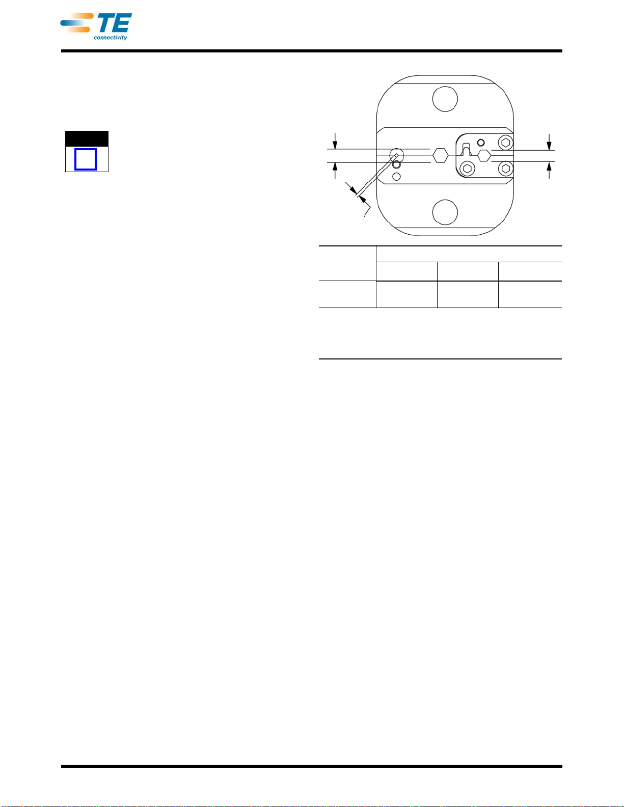
5.3. Measuring Die Opening
The die assembly will perform correctly as long as: 
(1) the product specified is correct for the application,
(2) the specific die assembly is used, (3) the die
assembly has been measured to ensure that the
openings are correct, and (4) the die assembly
bottoms.
Figure 5 provides information on die opening sizes.
For specific applications where wire stiffness, material,
or insulation may give different than standard
performance, it may be necessary to measure the
crimped ferrule, rather than to verify the size of the die
opening.
AB
C†
DIE
ASSEMBLY DIE OPENING (mm [in.])
A B C†
58046-1 3.00 ±0.08
[.118 ±.003] 2.39 ±0.10
[.094 ±.004] 0.610 - 0.673
[.0240 - .0265]
† NOTE: Alternate method to check “C” dimension is to crimp a
#20AWGsolidwire,andmeasurethecrimpheight.Onesidemay
be 0.051 [.0020] out of tolerance, as long as the average
measurements of both sides are within the dimension specified.
Figure 5
Crimp height inspection is performed through the
use of a micrometer with a modified anvil,
commonly referred to as a crimp height comparator. 
TE does not market crimp height comparators.
Refer to Instruction Sheet 408-7424 for detailed
information on obtaining and using a crimp height
comparator.
5.4. Ratchet Adjustment (Figure 6)
The tool frame assembly ratchet mechanism features
an adjustment wheel with numbered settings. If the
crimp height is not acceptable, adjust the ratchet as
follows:
1. Remove the lockscrew from the ratchet
adjustment wheel.
2. With a screwdriver, adjust the ratchet wheel from
the opposite side of the tool.
3. Observe the ratchet adjustment wheel. If a tighter
crimp is required, rotate the adjustment wheel
COUNTERCLOCKWISE to a higher-numbered
setting. If a looser crimp is required, rotate the
adjustment wheel CLOCKWISE to a lower-
numbered setting.
4. Replace the lockscrew.
5. Make a sample crimp and measure the crimp
height. If the crimp height is acceptable, secure the
lockscrew. If the dimension is unacceptable, remove
lockscrew and continue to adjust the ratchet, and
again measure a sample crimp
Screwdriver
Ratchet
Adjustment
Wheel
Lockscrew
(Typ)
408-6759
4of 4
Rev C
Figure 6
6. REPLACEMENT
Customer-replaceable parts are listed in Figure 7. A
complete inventory should be stocked and controlled
to prevent lost time when replacement of parts is
necessary. Order replacements through your 
TE Connectivity Representative, or call 
1-800-526-5142, or send a facsimile of your purchase
order to 1-717-986-7605, or write to:
CUSTOMER SERVICE (038-035)
TYCO ELECTRONICS CORPORATION
PO BOX 3608
HARRISBURG PA 17105-3608
For customer repair service, call 1-800-526-5136.
7. REVISION SUMMARY
•Revised crimp height comparator information.
•Updated document to corporate requirements.
Figure 7
REPLACEMENT PARTS
ITEM PART NUMBER DESCRIPTION QUANTITY PER ASSEMBLY
1 312224-1 LOCATOR 1
2 21028-2 PIN, Slotted Spring 2
3 1-21000-0 SCREW, Socket Head Cap 4
4 312228-1 CRIMPING DIE, Lower 1
5 312227-1 CRIMPING DIE, Upper 1
6 312226-1 INSULATION INSERT, Lower 1
7 312225-1 INSULATION INSERT, Upper 1
1
23
4
5
6
7
3
2