manuals.online logo
Brands
  1. Home
  2. •
  3. Brands
  4. •
  5. TE Connectivity
  6. •
  7. Crimping Tools
  8. •
  9. TE Connectivity PRO-CRIMPER III User manual

TE Connectivity PRO-CRIMPER III User manual

Instruction Sheet
©2011 Tyco Electronics Corporation, a TE Connectivity Ltd. Company
All Rights Reserved
*Trademark
TE Connectivity, TE connectivity (logo), and TE (logo) are trademarks. Other logos, product and/or Company names may be trademarks of their respective owners.
1of 4
TOOLING ASSISTANCE CENTER
1-800-722-1111
PRODUCT INFORMATION
1-800-522-6752
This controlled document is subject to change.
For latest revision and Regional Customer Service,
visit our website at www.te.com
LOC B
PRO-CRIMPER* III Hand Crimping
Tool Assembly 58573-1 with
Die Assembly 58573-2 408-4251
21 APR 11 Rev F
Figure 1
1. INTRODUCTION
PRO-CRIMPER III Hand Tool Assembly 58573-1
consists of PRO-CRIMPER III Hand Tool Frame
354940-1 and Die Assembly 58573-2. The tool
assembly is used to crimp the spare wire caps listed in
Figure 1 onto single unstripped wire with thin copper
insert and with or without a moisture-resistant inhibitor.
Read these instructions thoroughly before using the
tool assembly.
Dimensions in this instruction sheet are in metric
units [with U.S. customary units in brackets].
Figures are not drawn to scale.
For additional information on the hand tool frame, refer
to 408-9930.
Reasons for reissue of this instruction sheet are
provided in Section 8, REVISION SUMMARY.
2. DESCRIPTION (See Figure 1)
The tool consist of a stationary jaw and handle, a
moving jaw and handle, and an adjustable ratchet that
ensures full crimping. The tool features a ratchet
adjustment wheel for adjusting the crimp height.
The die assembly consists of an indenter (stationary
die) and an anvil (moving die). When closed, the dies
form four crimping chambers. Each die is held in the
tool frame by a single screw.
DIE ASSEMBLY
DIE ASSEMBLY
CRIMPINGCHAMBER
MARKING
WIRE INSULATION
DIAMETER RANGE
(mm [in.])
SPARE WIRE CAP SPARE WIRE CAP
COLOR CODE
Standard Moisture Resistant
58573-2
W 1.22-1.91 [.048-.075] 324484 324693 White
R 2.03-2.92 [.080-.115] 324485 324694 Red
B 3.05-3.68 [.120-.145] 324486 324695 Blue
Y 3.81-5.33 [.150-.210] 324487 324696 Yellow
NOTE
i
Die Assembly
Moving Jaw
Ratchet Adjustment
Wheel
Stationary Jaw
Back of Tool Frame
(Wire Side)
Pivot Pin
Ratchet
PRO-CRIMPER III Hand Tool
Frame 354940-1 (408-9930)
Stationary Handle
Moving Handle
The PRO-CRIMPER III Hand Crimping Tool is a “Commercial" grade tool and is
designed primarily for field installation, repair, maintenance work, or prototyping in
industrial, commercial, or institutional applications. Product crimped with this tool will
meet the crimp height requirement for hand tools in the appropriate Application
Specification (114-series), but may not comply with other feature parameters of the
specification. TE offers a variety of tools to satisfy your performance requirements.
For additional information, contact the Tooling Assistance Center at 1-800-722-1111.
Die Retaining Screw
(2 Places)
PROPER USE GUIDELINES
Cumulative Trauma Disorders can result from the prolonged use of manually powered hand tools. Hand tools are intended for occasional use and low
volume applications. A wide selection of powered application equipment for extended-use, production operations is available.
408-4251
2of 4
Rev F
3. INSTALLATION AND REMOVAL OF DIE ASSEMBLY
1. Close the tool handles until the ratchet releases,
then allow the handles to open fully.
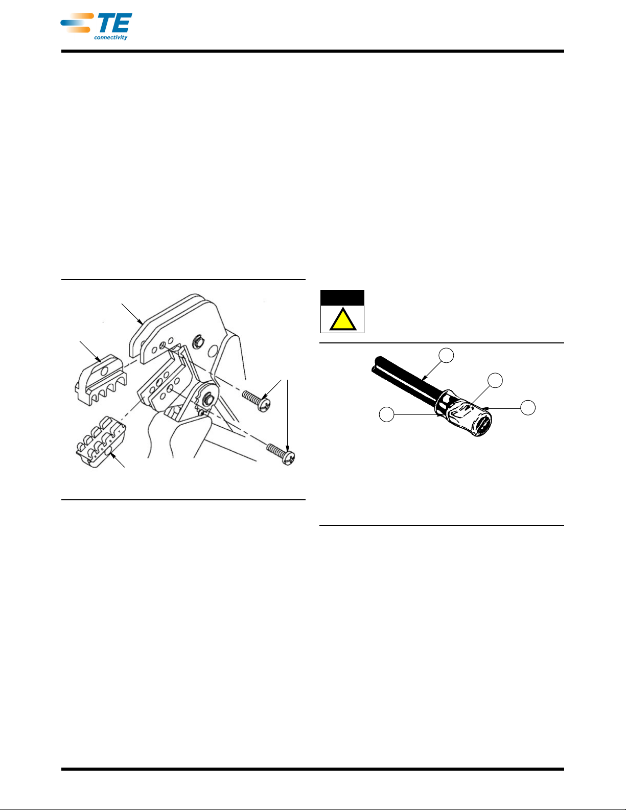
2. Insert the dies into the tool jaws as shown in
Figure 2, and align the retaining holes in each die
with the associated hole in the tool.
3. Thread, but do not tighten, the die retaining
screws into the holes.
4. Carefully close the tool handles, making sure that
the dies align properly.
5. Tighten the die retaining screws using the
appropriate screwdriver.
6. To disassemble, close the tool handles until the
ratchet releases, remove the two die retaining
screws, and slide the dies out of the tool jaws.
Figure 2
4. CRIMPING PROCEDURE
Refer to Figure 1, and select a spare wire cap for the
insulation diameter of the wire being used. Then
proceed as follows:
1. Close the tool handles until the ratchet releases,
then allow the handles to open FULLY.
2. Identify the color code of the spare wire cap, and
insert the spare wire cap into the crimping chamber
with the same color code. Make sure that the spare
wire cap is fully inserted.
3. Begin closing the tool handles until the spare wire
cap is held firmly in place. DO NOT deform the cap.
4. Insert the unstripped wire completely into the
spare wire cap. When bottoming the wire in a
moisture-resistant spare wire cap, greater insertion
force must be exerted on the wire to displace the
inhibitor in the spare wire cap.
5. Close the tool handles until the ratchet releases.
6. Allow the tool handles to open FULLY, and turn
the spare wire cap and wire one quarter of a turn
while pulling lightly on the wire until the spare wire
cap is free from the crimping chamber.
7. Refer to Figure 3, and inspect the crimped spare
wire cap for the following:
— The crimp should be near the center of the insert
in the spare wire cap, and the wire should be
bottomed in the spare wire cap.
— Double check that the correct spare wire cap was
used for the wire insulation diameter, and make
sure that the correct crimping chamber was used.
If the spare wire cap fails inspection, cut the wire
from the spare wire cap, then apply a new spare
wire cap to the wire by carefully following the
crimping procedure.
DO NOT use defective or damaged products.
Figure 3
5. RATCHET ADJUSTMENT
The tool ratchet mechanism features an adjustment
wheel with numbered settings. The adjustment wheel
controls the amount of handle pressure exerted on the
jaws during crimping. If the crimp is not acceptable,
adjust the ratchet as follows:
1. Remove the lockscrew from the ratchet
adjustment wheel. Refer to Figure 4.
2. Using a screwdriver, adjust the ratchet wheel
from the front of the tool.
3. Observe the ratchet adjustment wheel. If a tighter
crimp is required, rotate the adjustment wheel
counterclockwise to a higher-numbered setting. If a
looser crimp is required, rotate the adjustment
wheel clockwise to a lower-numbered setting.
Indenter
Die
Anvil
Die
Die
Retaining
Screws
Jaws
!
CAUTION
1
2
3
1 Crimp near center of insert; spare wire cap was fully
bottomed in closed dies.
2 Correct wire insulation diameter for spare wire cap was used.
3 Wire bottomed in spare wire cap.
4 Spare wire cap insulation color matches die crimping
chamber marking.
4
408-4251
3of 4
Rev F
Figure 4
4. Re-install the lockscrew.
5. Make a sample crimp. If the crimp is acceptable,
the adjustment setting is correct. If the crimp is
unacceptable, continue to adjust the ratchet, and
again measure a sample crimp.
6. MAINTENANCE AND INSPECTION
6.1. Maintenance
1. Ensure that the tool frame and dies are clean by
wiping them with a clean, soft cloth. Remove any
debris with a clean, soft brush. Do not use objects
that could damage any components.
2. When not in use, keep tool handles closed to
prevent objects from becoming lodged in the dies,
and store in a clean, dry area.
3. Remove all lubrication and accumulated film from
the dies by immersing the dies in a suitable
commercial degreaser.
6.2. Visual Inspection
1. Inspection of the tool and dies should be made on
a regular basis to ensure that they have not become
worn or damaged.
2. Make sure that the proper die retaining screws
are properly secured.
3. Inspect the crimping chambers of the die
assembly for flattened, chipped, worn, or broken
areas. If damage or abnormal wear is evident, the
dies must be replaced. Refer to Section 7,
REPLACEMENT AND REPAIR.
6.3. Measuring Die Opening
The tool assembly will perform correctly as long as:
(1) the product specified is correct for the die
assembly, (2) the correct product is used in the
matching crimping chamber of the die assembly,
(3) the die assembly has been measured to ensure
that the openings are correct, and (4) the dies bottom
on each other.
Figure 5 provides dimensions for the die openings.
Figure 5
7. REPLACEMENT AND REPAIR
Available separately, Repair Kit 679221-1 includes a
replacement nut and a variety of pins, rings, screws,
and springs. If the dies are damaged or worn
excessively, they must be replaced.
Order the repair kit, tool assembly, and die assembly
through your representative, or call 1-800-526-5142,
or send a facsimile of your purchase order to
717-986-7605, or write to:
CUSTOMER SERVICE (038-035)
TYCO ELECTRONICS CORPORATION
PO BOX 3608
HARRISBURG PA 17105-3608
8. REVISION SUMMARY
Revisions to this instruction sheet include:
•Changed company logo
Screwdriver
Lockscrew
RatchetAdjustment
Wheel
DIE
ASSEMBLY
DIE OPENING DIMENSION (mm [in.])
WRB Y
58573-2 1.83
[.072]
2.26
[.089]
2.95
[.116]
3.61
[.142]
W
R
Y
B
Note: Not to Scale
408-4251
4of 4
Rev F
Tooling Compatible with Die Assembly 58573-2
PRO-CRIMPER III Hand Tool Frame 354940-1
(Instruction Sheet 408-9930)
SDE-SA Hand Tool 9-1478240-0
(Instruction Sheet 408-8851)
SDE Bench Terminator 1490076-2
(Customer Manual 409-10052)
626 Adapter 679304-1
(Instruction Sheet 408-4070)
Electro-Hydraulic (BT 3500 Battery-Hydraulic)
Hand Tool Kits 2031400-[ ]
(Customer Manual 409-10095)
“C”-Head Assembly 2031450-1
(Instruction Sheet 408-10311)
Closed Head Assembly 2031460-1
(Instruction Sheet 408-10312)

Other manuals for PRO-CRIMPER III

17

This manual suits for next models

2

Other TE Connectivity Crimping Tools manuals

TE Connectivity STRATO-THERM 314935-1 User manual

TE Connectivity

TE Connectivity STRATO-THERM 314935-1 User manual

TE Connectivity 2392570-1 User manual

TE Connectivity

TE Connectivity 2392570-1 User manual

TE Connectivity Faston Series User manual

TE Connectivity

TE Connectivity Faston Series User manual

TE Connectivity 90117 Instruction Manual

TE Connectivity

TE Connectivity 90117 Instruction Manual

TE Connectivity 2378809-1 User manual

TE Connectivity

TE Connectivity 2378809-1 User manual

TE Connectivity ERGOCRIMP 5-1579001-1 User manual

TE Connectivity

TE Connectivity ERGOCRIMP 5-1579001-1 User manual

TE Connectivity 2063528-1 User manual

TE Connectivity

TE Connectivity 2063528-1 User manual

TE Connectivity 2392945-1 User manual

TE Connectivity

TE Connectivity 2392945-1 User manual

TE Connectivity 408-8569 User manual

TE Connectivity

TE Connectivity 408-8569 User manual

TE Connectivity 543344- 1 User manual

TE Connectivity

TE Connectivity 543344- 1 User manual

TE Connectivity 528050-3 User manual

TE Connectivity

TE Connectivity 528050-3 User manual

TE Connectivity SDE-SA User manual

TE Connectivity

TE Connectivity SDE-SA User manual

TE Connectivity PRO-CRIMPER III User manual

TE Connectivity

TE Connectivity PRO-CRIMPER III User manual

TE Connectivity 90281-1 User manual

TE Connectivity

TE Connectivity 90281-1 User manual

TE Connectivity 607949-1 User manual

TE Connectivity

TE Connectivity 607949-1 User manual

TE Connectivity 2362810-1 User manual

TE Connectivity

TE Connectivity 2362810-1 User manual

TE Connectivity SDE-SA User manual

TE Connectivity

TE Connectivity SDE-SA User manual

TE Connectivity 58422-1 User manual

TE Connectivity

TE Connectivity 58422-1 User manual

TE Connectivity SDE-SA User manual

TE Connectivity

TE Connectivity SDE-SA User manual

TE Connectivity SDE-SA User manual

TE Connectivity

TE Connectivity SDE-SA User manual

TE Connectivity 2063624-1 User manual

TE Connectivity

TE Connectivity 2063624-1 User manual

TE Connectivity 2368740-1 User manual

TE Connectivity

TE Connectivity 2368740-1 User manual

TE Connectivity 46073 User manual

TE Connectivity

TE Connectivity 46073 User manual

TE Connectivity SDE-SA 2389861-1 User manual

TE Connectivity

TE Connectivity SDE-SA 2389861-1 User manual

Popular Crimping Tools manuals by other brands

Emerson Klauke MAPAX325CFM manual

Emerson

Emerson Klauke MAPAX325CFM manual

Tyco Electronics CERTI-CRIMP 90418-1 instruction sheet

Tyco Electronics

Tyco Electronics CERTI-CRIMP 90418-1 instruction sheet

JST CS 10-WC-SF1002 instruction manual

JST

JST CS 10-WC-SF1002 instruction manual

Emerson Klauke ESG 25CFB manual

Emerson

Emerson Klauke ESG 25CFB manual

BEX ProBEX PBO instruction sheet

BEX

BEX ProBEX PBO instruction sheet

Cembre B135-C Operation and maintenance manual

Cembre

Cembre B135-C Operation and maintenance manual

Cembre B1350-CA Operation instructions

Cembre

Cembre B1350-CA Operation instructions

molex 35745 Series Specification sheet

molex

molex 35745 Series Specification sheet

Staubli PV-CZM Series operating instructions

Staubli

Staubli PV-CZM Series operating instructions

Telegärtner PEW 12 instruction sheet

Telegärtner

Telegärtner PEW 12 instruction sheet

Gates Power Crimp 707 Safety and operating manual

Gates

Gates Power Crimp 707 Safety and operating manual

Hilti NCR 120 PC-A22 Original operating instructions

Hilti

Hilti NCR 120 PC-A22 Original operating instructions

JST CS10-WC110 instruction manual

JST

JST CS10-WC110 instruction manual

molex 63819-3700 manual

molex

molex 63819-3700 manual

Greenlee GATOR EK1230 instruction manual

Greenlee

Greenlee GATOR EK1230 instruction manual

molex 63816-1000 Operation manual

molex

molex 63816-1000 Operation manual

KIMBALL MIDWEST 27-799 instruction manual

KIMBALL MIDWEST

KIMBALL MIDWEST 27-799 instruction manual

molex 63811-7000 Specification sheet

molex

molex 63811-7000 Specification sheet

manuals.online logo
manuals.online logoBrands
  • About & Mission
  • Contact us
  • Privacy Policy
  • Terms and Conditions

Copyright 2025 Manuals.Online. All Rights Reserved.