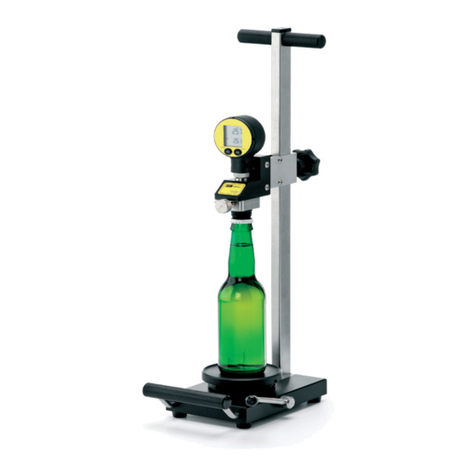
Pentair HAFFMANS RPU-352 User manual

W W W.HAFFMANS.NL
HAFFMANS
W W W.HAFFMANS.NL
HAFFMANS
INSTRUCTION MANUAL
REDPOST PU MONITOR
TYPE RPU-352/353


Essential reading!
Haffmans BV is not responsible for any damage caused by the owner’s failure to follow the instructions given in this
manual. Haffmans BV is not responsible for print or translation errors in this edition of the manual. The specifications
and design of this product are subject of change without notice. All rights reserved. No part of this publication may be
reproduced or distributed in any form or by any means, or stored in a database or retrieval system, without the prior
written permission of Haffmans BV.
Art. no. : 107.035
Release date : 15-07-2010
Version : D


HAFFMANS RPU 352, RPU 353, RPC 80 RPC 50
2
RPU 352, RPU 353, RPC 80, RPC 50 Page 5 of 112
Table of contents
1
Technical specifications 9
2
Safety 11
2.1
Symbols 11
2.2
Precautions and safety instructions 11
3
Installation 13
3.1
Unpacking 13
4
Operation 15
4.1
Controls 15
4.2
I/O switch 15
4.3
Indicator 15
4.4
Display illumination 16
4.5
Switch functions and icons 16
4.6
Auto power on 16
4.7
Auto power off 16
4.8
Low battery condition 17
5
Starting 19
5.1
Preparing the instrument 19
5.2
Pressure zero setting Only for PRU-353 21
5.3
Thermometer 21
5.4
Starting the recording 21
6
Recording 23
6.1
Stopping the recording 23
6.2
Screen temperature 23
7
Results 25
7.1
Results displays 25
7.2
Main menu 25
7.3
Calculated results 25
7.4
Erasing a file 26
8
Calculated Results 27
8.1
Total PU achieved 27
8.2
Unique ID number 27
8.3
Total recording time 27
8.4
Maximum temperature 27
8.5
Time near maximum temperature 27
8.6
Temperature at pasteuriser exit 28
8.7
PU cut-off temperature 28
8.8
Time adding PU’s 28
8.9
Maximum pressure Only for PRU-353 28

HAFFMANS RPU 352, RPU 353, RPC 80 RPC 50
2
Page 6 of 112 RPU 352, RPU 353, RPC 80, RPC 50
8.10
Time near maximum pressure Only for PRU-353 28
8.11
Reason for stopping 28
9
Graph 29
9.1
Cursor movement 29
9.2
Graph lines 30
9.3
Off-scale records 30
10
Full List 31
10.1
Time line movement 31
11
Battery Charging 33
11.1
Battery information 33
11.2
Battery temperature 33
12
Menus 35
12.1
Moving the highlight 35
12.2
Selecting an item 35
13
Key Plug (Configuration) 37
13.1
Output to other equipment 37
13.2
Language 37
13.3
Display contrast 37
13.4
Clock 38
13.5
Display units 38
13.6
Active channels 39
13.7
PU cut-off temperature 39
13.8
PU calculation – Base 39
13.9
PU calculation – Z 39
13.10
PU calculation – Fahrenheit 39
13.11
Recording interval 40
13.12
Equipment number 40
13.13
Mains frequency 40
13.14
Leaving configuration 40
14
Output 41
14.1
Stand alone operation 41
14.2
Connection to RPC-80 41
14.3
Connection to PC 41
15
Maintenance 43
16
Frequently Asked Questions 45
16.1
Battery and battery charging 45
16.2
Controls 47
16.3
Results 48
Instruction manual RPC-80 Printer/charger 51

HAFFMANS RPU 352, RPU 353, RPC 80 RPC 50
2
RPU 352, RPU 353, RPC 80, RPC 50 Page 7 of 112
17
Technical specifications 53
18
Introduction 55
19
Unpacking 57
20
Control panel 59
21
Use 61
21.1
Switching on 61
21.2
Connecting the monitor 61
21.3
Printing recorded files 62
21.4
After printing 62
21.4.1
200 Series P.U. monitors. 62
21.4.2
100 Series P.U. Monitors. 62
22
Configuration settings 63
22.1
Clock setting 63
22.2
Report printing 63
22.3
Template setting 63
23
Configuration MENU section 65
23.1
General format set-up 65
23.1.1
Select language 65
23.1.2
Select decimal point 65
23.1.3
Set graph formats 65
23.1.4
P.U.-user 65
23.2
P.U. calculation Set-up 66
23.3
Template set-up 67
23.3.1
Template recording 68
23.4
Template exchange 69
23.5
Editing a template name 70
23.6
Monitor set-up 70
23.7
RPC-80 Set-up 70
23.8
Full list set-up 71
23.9
Printer set-up 71
23.10
External link set-up 72
23.11
Finished set-up : exit 73
24
Printed results 75
24.1
Results 75
24.2
Status report 75
25
System errors 77
25.1
System error 02 & 04. 77
25.2
System error 08 & 09. 77
26
Faulty operation 79

HAFFMANS RPU 352, RPU 353, RPC 80 RPC 50
2
Page 8 of 112 RPU 352, RPU 353, RPC 80, RPC 50
26.1
B-messages 79
26.2
C-messages 79
26.3
M-messages 81
26.4
P-messages 82
26.5
T-messages 83
27
Back-up battery 85
Instruction manual RPC-50, charger interface 87
28
Technical specifications 89
29
Unpacking 91
30
Operating 93
30.1
Battery Charging 93
30.2
Connection to PC 93
31
Safety 95
Appendix I Background information 97
Appendix II Diagrams 99
Appendix III Customer service 101
Appendix IV Terms of guarantee 103
Appendix V EC Declaration of conformity RPU 352 / 353 105
Appendix VI EC Declaration of conformity RPC 50 107
Appendix VII EC Declaration of conformity RPC 80 109
Appendix VIII Spare parts 111

HAFFMANS RPU 352, RPU 353, RPC 80 RPC 50
2
RPU 352, RPU 353, RPC 80, RPC 50 Page 9 of 112
1 TECHNICAL SPECIFICATIONS
Storing data Max No. of files 4 * (a file is a single recording run)
Max No. of fields 15860 (a field is one channel
record)
Recording timer setting 4 hours * (the maximum recording
run)
Recording interval setting 10 seconds (user can select from 2
s to 60 s)
Only for RPU-352: * Other values available to special order. Recording both channels at 10 second intervals a total of 22
hours recording can be stored.
Only for PRU-353: * Other values available to special order. Recording all 3 channels at 10 second intervals a total of 14.6
hours recording can be stored.
Recording
inputs Temperature
Only for PRU-353:
Pressure
Number of input channels 2 1
Nominal range -5 to +105 ºC
* -0.5 to +18.0 bar
gauge*
Resolution 0.02 ºC 0.002 bar
* The display can show results in alternative units if required.
Measuring
accuracy Worst case, all errors, including sensors
Temperature ± 0.25 ºC (sensor in range 40 to 80
ºC)
± 0.4 ºC (over rest of range)
Only for PRU-353:
Pressure
(after setting zero) ± 0.08 bar (sensor in range 0 to 8
bar gauge and 40 to 80 ºC)
± 0.2 bar (all other conditions)
All sensors are interchangeable within the accuracy specification
Operating
conditions Operation outside these limits may cause permanent damage
Instrument -10 to +85 ºC
Temperature sensor -30 to +150
ºC
Only for PRU-353:
Pressure sensor up to +20 bar gauge

HAFFMANS RPU 352, RPU 353, RPC 80 RPC 50
2
Page 10 of 112 RPU 352, RPU 353, RPC 80, RPC 50
Battery life From a fully charged battery
Example (a) 2 maximum runs Record 4 hours, display (with
backlight) 20 minutes
Example (b) 15 typical runs Record 40 minutes, display (with
backlight) 5 minutes
Assumes final recording is completed within one week of the first
Dimensions (Length x Width x Height)
In frame 380 x 175 x 230 mm
Weight 9.25 kg Including
frame
Dimensions and weight are inclusive of carrying frame, can holder and can pressure fitting
Materials Stainless steel, toughened glass and PET-P plastic.
Calculation of pasteurisation units (PU) can take place in the RPU-352, PRU-353
Accuracy Better than ± 0.001% for calculation
alone *
Range 0 to 9999.9
PU
Resolution 0.1 PU
* Note that a temperature measurement error of ± 0.25 ºC represents ± 8% error in PU value.

HAFFMANS RPU 352, RPU 353, RPC 80 RPC 50
2
RPU 352, RPU 353, RPC 80, RPC 50 Page 11 of 112
2 SAFETY
2.1 SYMBOLS
Attention, warning and danger symbols used in this manual have the following significance.
Attention!
Information for correct or effective use of the equipment.
Warning
Incorrect or careless use can cause serious damage to the
equipment.
Failure to observe this information can result in major
personal injury or loss of life.
2.2 PRECAUTIONS AND SAFETY INSTRUCTIONS
Always follow basic safety precautions when using this equipment to reduce risk of injury.
Before using the equipment, read and understand the operating instructions in this manual.
This equipment is intended to monitor the pasteurisation process in tunnel pasteurisers. It
should not be used for any other purpose.
The equipment should only be connected to other equipment intended for the purpose and
manufactured by Redpost Electronic Products Ltd. Suitable battery chargers are RPC-50 and
RPC-80. Battery chargers from other manufacturers should not be used, they may result in
danger.
The equipment may remain hot for some time after being taken from the pasteuriser. Wear
protective gloves when carrying.
Always place the equipment on a level, stable surface. Do not place on shelves above eye
level.

HAFFMANS RPU 352, RPU 353, RPC 80 RPC 50
2
Page 12 of 112 RPU 352, RPU 353, RPC 80, RPC 50

HAFFMANS RPU 352, RPU 353, RPC 80 RPC 50
2
RPU 352, RPU 353, RPC 80, RPC 50 Page 13 of 112
3 INSTALLATION
3.1 UNPACKING
This manual was written for the RPU-352 and PRU-353. You will find all the information in this
manual. When there is specific information for one product, it is written with the specific item.
Before despatch the RPU-352, PRU-353 was checked and tested by Haffmans B.V. Make sure
that the content of the delivery is complete and undamaged.
If the delivery is incomplete or damaged, please contact Haffmans B.V. or the
representative/agent designated by Haffmans B.V, immediately (appendix III). Always include the
serial number, order number or invoice number (given by Haffmans B.V.) of the RPU-352, PRU-
353 in the correspondence.
The delivery for the RPU-352 contains: The delivery for the PRU-353 contains:
1 PE-Monitor Type RPU-352 1 PE-Monitor Type PRU-353 for bottles and cans
1 Can/bottle holder PRU-353
1 Quick change facility 1 Quick change facility
1 Spray water temperature probe 1 Spray water temperature probe
1 Test plug 60°C 1 Test plug 60°C
1 Dummy temperature probe 1 Dummy temperature probe
1 Connector grease 1 Connector grease
1 Set of operating magnets (pkg 2) 1 Set of operating magnets (pkg 2)
1 Temperature probe, Lg 150 mm with set
of distance tubes (8 pieces) 1 Temperature probe, Lg 150 mm with set of
distance tubes (8 pieces)
1 Plate with bottle holder, Ø 55-68 mm 1 Plate with bottle holder, Ø 55-68 mm
1 K-plug 1 K-plug
1 Manual RPU-352 and PRU-353 1 Manual RPU-352 and PRU-353
Optional: Optional:
Temperature probe Temperature probe
1 Lg 110 mm* 1 Lg 110 mm*
1 Lg 190 mm* 1 Lg 190 mm*
1 Lg 230 mm* Plate with bottle holder
1 Lg 270 mm* 1 Ø 45-55 mm*
1 Lg 310 mm* 1 Ø 68-80 mm*
1 Lg 350 mm* 1 Ø 80-90 mm*
1 Lg 390 mm* 1 Ø 90-100 mm*
Plate with bottle holder 1 Play Back Unit, Type RPC-50
1 Ø 45-55 mm* 1 Play Back Unit, Type RPC-80
1 Ø 68-80 mm*
1 Ø 80-90 mm*
1 Ø 90-100 mm*
1 Play Back Unit, Type RPC-50
1 Play Back Unit, Type RPC-80
*Depending on the item(s) ordered.

HAFFMANS RPU 352, RPU 353, RPC 80 RPC 50
2
Page 14 of 112 RPU 352, RPU 353, RPC 80, RPC 50

HAFFMANS RPU 352, RPU 353, RPC 80 RPC 50
2
RPU 352, RPU 353, RPC 80, RPC 50 Page 15 of 112
4 OPERATION
4.1 CONTROLS
There are four control switches arranged around the display screen. Operate the
switches by touching one end of the actuator onto the glass in the marked area.
Keep the actuator in position until you see a change in the display or the flashing
indicator.
The two top switches are used for the main control functions. They take a few
seconds to operate so that there is less chance of any accidental actions.
4.2 I/O SWITCH
The top left switch is the I/O (on/off) switch. Switch the instrument on by
activating this switch. Switch the instrument off by activating and holding this
switch for at least ten seconds. The display shows you what is happening.
Remove the actuator after the instrument switches off.
If there are any recorded files they will be saved during the time the instrument is
switched off.
You cannot switch the instrument off when the battery is charging from a Redpost
printer/charger unit or a Redpost battery charger.
4.3 INDICATOR
The small green lamp on the panel flashes once per second to show that the
instrument is operating. This lamp also flashes quickly five times to acknowledge
the action of either of the two top switches.
DISPLAY
I/O
Display
Icon
Flashing
“ON” indicator Icon relates to
this switch

HAFFMANS RPU 352, RPU 353, RPC 80 RPC 50
2
Page 16 of 112 RPU 352, RPU 353, RPC 80, RPC 50
4.4 DISPLAY ILLUMINATION
The I/O (on/off) switch also turns on the backlight that lights up the display.
When any switch is operated or there is any other activity, such as connecting a
probe, the backlight will turn on. It will turn off again after a short time to save
battery power. Activate the I/O switch (for about half a second) to turn on the
backlight without causing any other action.
If there is very little charge in the battery then the backlight will not turn on. This
saves unnecessary battery drain.
4.5 SWITCH FUNCTIONS AND ICONS
The I/O (on/off) switch always keeps the same function but for the other three
switches the display will show a small “icon” to indicate the function of each
switch. The icon is in the same corner as the switch it relates to. The switch icon
becomes inverted (black for white) when the switch is operated. If a switch has
no icon then it has no function at that time.
4.6 AUTO POWER ON
The instrument will automatically switch on when it is connected to a Redpost
printer/charger or a Redpost battery charger. This allows the battery charging to
be controlled and the charging information to be displayed.
The I/O (on/off) switch will not turn the instrument off while it is connected to a
charger but it can still be used to turn on the display backlight.
4.7 AUTO POWER OFF
The instrument uses several methods to reduce battery power consumption. The
automatic control of the display backlight is described above.
If the instrument is idle and waiting to record a file it will automatically switch off
after ten minutes. The instrument is idle if no switches are activated, no data
communication is taking place and it is not connected to an active battery
charger.
If the instrument is idle and displaying the results of a recorded file it will
automatically switch off after twenty minutes.
When the instrument switches off automatically any recorded files are saved.
To resume normal operation activate the I/O (on/off) switch or connect the
instrument to a Redpost battery charger.

HAFFMANS RPU 352, RPU 353, RPC 80 RPC 50
2
RPU 352, RPU 353, RPC 80, RPC 50 Page 17 of 112
4.8 LOW BATTERY CONDITION
If recording is taking place when the battery charge level falls below 15%
then recording will stop and the file will be saved. This ensures that
recordings cannot be corrupted by low battery condition. The results
screen will show the reason for stopping.
If there is less than 15% charge in the battery then the backlight cannot be
switched on. This helps to ensure that the battery lasts for as long as
possible. The backlight increases the battery drain by about four times.
At an even lower level of charge (below 5%) the whole instrument will turn
off. Any recorded files will be saved. If you switch the instrument on again
in this state it will stay on for only a few seconds. Connect the instrument
to a Redpost battery charger as soon as possible.
The instrument continuously monitors its own battery use and battery
charging to gauge the amount of charge that remains in the battery. If the
battery voltage falls to a low level unexpectedly it may indicate that the
battery is not correctly holding its charge. This can happen after several
years of use. If this problem occurs the display will warn you that the
battery may need to be replaced. More information can be found in the
“Maintenance” section.

HAFFMANS RPU 352, RPU 353, RPC 80 RPC 50
2
Page 18 of 112 RPU 352, RPU 353, RPC 80, RPC 50

HAFFMANS RPU 352, RPU 353, RPC 80 RPC 50
2
RPU 352, RPU 353, RPC 80, RPC 50 Page 19 of 112
5 STARTING
5.1 PREPARING THE INSTRUMENT
Switch on the instrument. If there are any problems, such as insufficient charge in the battery,
the display will give the information you need. Before the temperature probes are connected
the location and numbering of the sockets is shown on the display.
Set up the bottle or can in the correct size holder and fit the correct length temperature probe.
Connect this probe into the channel 1 socket. Channel 1 is to the right of the display. When
calculating the results channel 1 is given most importance and is assumed to show the product
temperature.
Select the spray probe or second container temperature probe and connect it to channel 2.
Channel 2 is to the left of the display.
Both sockets must always be occupied. To run without one of the probes you can connect a
dummy temperature probe. (A special plug marked with a ‘T’.) You can also configure a
channel to be permanently inactive: see the section “Key Plug”. An inactive channel is shown
by an X on the screen.
Only for PRU-353:
Pressure
(channel 3)
Start
recording
Temperature of
probe (channel 2)
Temperature of
probe (channel 1)
Set pressure
zero

HAFFMANS RPU 352, RPU 353, RPC 80 RPC 50
2
Page 20 of 112 RPU 352, RPU 353, RPC 80, RPC 50
Only for RPU-353:
In order to make a record run the pressure sensor can be connected in the same bottle as the
temperature sensor.
Preparation for measurement in bottles and cans. For bottles an additional centre ring (1) is
needed to centre the bottle. Preparations are:
1. Adjust the Piercing mechanism (2) by placing a sufficient amount of distance tubes
Bottle length = 80 (base ring) + n x 40 (distance ring) + n x 5 (distance ring)
2. Tighten nut (3).
3. Place bottleor can on the base (4)
4. Lower the plate with pressure adapter and temperature sensor (5).
5. Close the piercing mechanism (2)
6. Optional snifting. By pushing the levers (2) up and down quickly, the pressure in the
bottle or can gets down to the atmospheric pressure
7. Push the temperature sensor (6) down into the bottle and adjust the sensor with the
screw (7). This process is described in the section “Appendix 1: Background Information”
1
2
3
4
5
7
6
This manual suits for next models
1
Table of contents
Other Pentair Measuring Instrument manuals

Pentair
Pentair LINCOLN A Series Owner's manual

Pentair
Pentair Point Four Tracker User manual

Pentair
Pentair EVERPURE EV4339-31 User manual

Pentair
Pentair HAFFMANS c-DGM User manual

Pentair
Pentair INTELLISYNC User manual

Pentair
Pentair HAFFMANS 006.625 User manual

Pentair
Pentair GOYEN MECAIR PEM User manual

Pentair
Pentair HAFFMANS GMT User manual