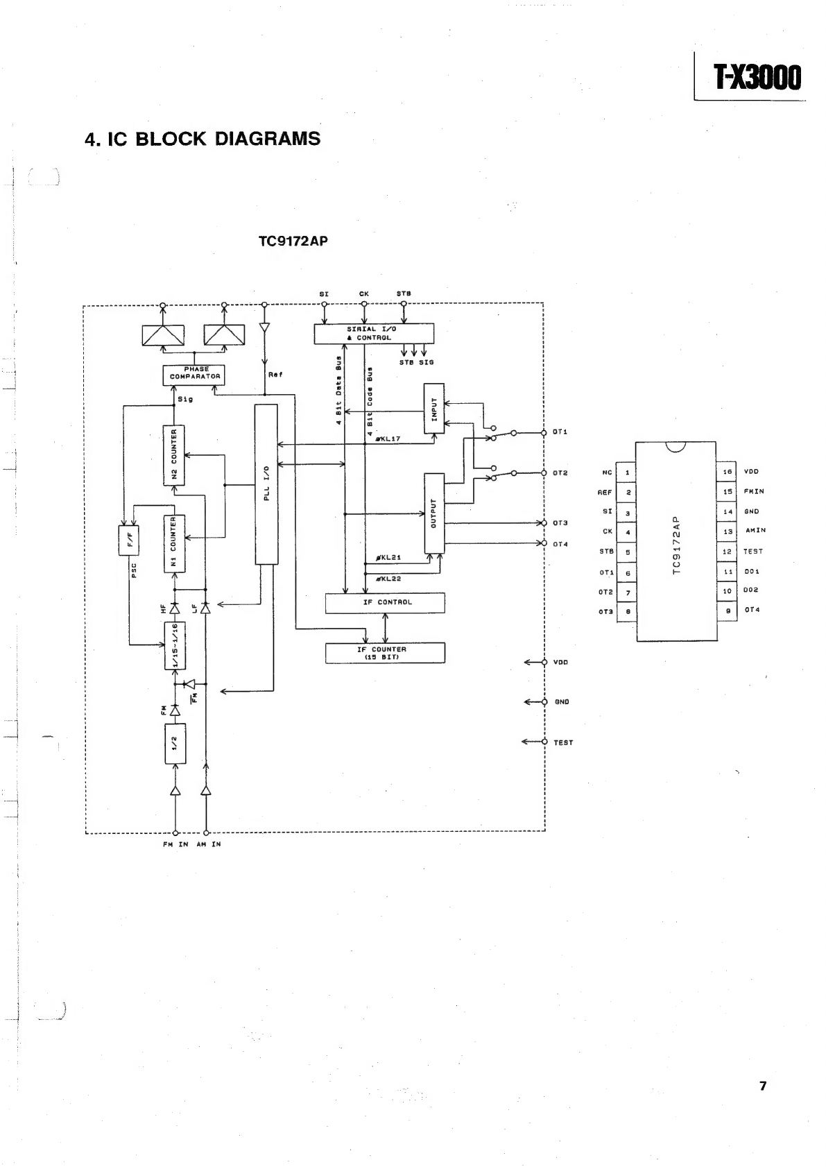
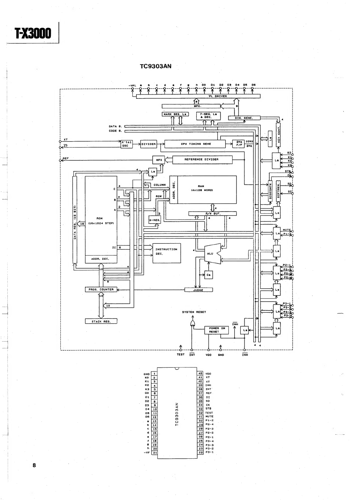
Teac T-X3000 User manual

TEAC.
kat
SERVICE
MANUAL
T-X3000
AM/FM
Digital
Synthesizer
Tuner
As
regards
the
resistors
and
capacitors,
refer
to
the
circuit
diagrams
and
the
PCB
ass'y
drawing
contained
in
this
manual.
@
Parts
marked
with"
require
longer
delivery
time.
@
A
parts
marked
with
this
sign
are
safety
critical
components.
They
must
always
be
replaced
with
identical
component-refer
to
the
TEAC
parts
List
and
ensure
exact
replacement.
@
PC
boards
shown
viewed
from
parts
side.
Effective:
July,
1991
5704054000

—-FX3000
1.
SPECIFICATIONS
[FM
Section]
(IHF)
Tuning
Cover
Range:
~
87.5
MHz
~
108.0
MHz
(100
kHz
steps,
USA/Canada)
87.50
MHz
—
108.00
MHz
(50
kHz
steps,
Europe/UK/Australia/
General
Export)
Usable
Sensitivity
(IHF):
Mono:
13.2
dBf
(Europe/UK),
10.8
dBf
(Others)
50
dB
Quieting
Sensitivity:
Mono:
19.9
dBf
(Europe/UK),
17
dBf
(Others)
Stereo:
42-dBf
(Europe/UK),
39.2
dBf
(Others)
Alternate
Channel
Selectivity:
(98
MHz
£400
kHz)
78
dB
(Europe/UK),
68
dB
(Others)
Image
Response
Ratio:
80
dB
(Europe/UK),
43
dB
(Others)
RF
intermodulation:
©
70
dB
(Europe/UK),
65
dB
(Others)
Frequency
Response:
20
—
15,000
Hz
(+1
dB/-2
dB)
Capture
Ratio:
1.7
dB
(at
98
MHz)
Distortion
(at
65
dBf,
98
MHz):
Mono:
0.2
%,
Sterea:
0.4
%
"
Signal-to-Noise
Ratio
(at
65
dBf,
1
kHz):
Mono:
80
dB,
Stereo:
72
dB
AM
Suppression
Ratio:
65
dB
Stereo
Separation
(1
kHz):
40
dB
Output
(Level/impedance):
600
mV/
2.2
kahms
[AM
Section}
Tuning
Cover
Range:
530
—
1710
kHz
(10
kHz
steps,
USA/Canada)
522
—
1611
kHz
(9
kHz
steps,
Europe/UK/
Australia/General
Export)
Usable
Sensitivity:
50
dB/m
(316
V/m,
Loop
Antenna)
Selectivity:
25
dB
(+9
kHz
at
999
kHz)
Image
Response
Ratio:
42
dB
(at
999
kHz)
2.
CHECKS
AND
ADJUSTMENTS
FM
TEST
CONNECTIONS
MPX
Modulator
Dummy
ANT.
47k
Q
LA126
Connect
test
equipment
as
shown
in
diagram.
(A
DC
voltmeter
shall
be
connected
between
test
points
TP-2
and
TP-3
on
the
Main
PCB--that
is,
to
the
ends
of
R213.)
Dummy
Load
Connections
on
the
Main
PCB
inside
the
tuner
IF
Response
Ratio:
60
dB
(at
999
kHz)
Distortion:
0.5
%
(85
dB/m
at
999
kHz)
Signal-to-Noise-Ratio:
50
dB
(at
85
dB/m)
Output
(Level/Impedance):
200
mV/
2.2
kohms
[General]
Power
Requirement:
120
V
AC,
60
Hz
(USA/Canada)
220
V
AC,
50
Hz
(Europe)
240
V
AC,
50
Hz
(UK/Australia)
115/230
V
AC,
50
—
60
Hz
(General
Export)
Power
Consumption:
10
W
Dimensions
(WxHxD):
435
x
82
x
276:
mm
Weight
(net):
2.9
kg
Accessory:
300/75
ohm
Matching
Trans-
former
(Europe/UK
only),
T-bar
FM
Antenna,
AM
Loop
Antenna,
RCA
pin
plug
Cord,
Owner's
Manual
*}mprovements
may
result
in
specification
or
feature
changing
without
notice.
Distortion
Meter

.
FM
Discrminator
Adjustment
.
Set
the
tuner
to
its
FM
position.
.
Tune
the
tuner
to
a
98
MHz
frequency
and
load
this
into
any
preset
station
memory.
.
Keep
the
tuner
available
to
receive
the
frequency
of
98
MHz.
.
Switch
the
FM
Signal
Generator
so
that
the
tuner
is
fed
with
this
signal
:
mono
carrier
of
98
MHz,
modulating
frequency
of
1
kHz,
modulation
rate
of
100%
(75
kHz
dev.),
at
a-level
of
65
dBf.
;
‘Adjust
T21
until
the
DC
voltmeter
connected
between
TP-2
and
TP-3
reads
0
V
+/-1
mV.
.
Switch
the
filter
box
to
select
a
200-15,000
Hz
band
pass
filter
(BPF),
and
check
for
0.6%
THD
or
less
as
read
on
the
distortion
meter.
.
TUNED
LED
Lighting
Level
Adjustment
1.
The
tuner
shall
be
tuned
to
98
MHz
as
before.
.
Switch
the
FM
Signal
Generator
so
that
the
tuner
is
fed
with
this
signal
:
carrier
of
98
MHz,
modulating
frequency
of
1
kHz,
modulation
rate
of
100%
(75
kHz
dev.),
at
a
25
dB
level.
.
Adjust
VR21
until
the
TUNED
indicator
lights.
FX3000
3.
IF
Coil
Adjustment
(only
when
THD
is
out
of
specs}
1.
Make
sure
that
the
tuner
is
set
for
98
MHz.
2.
Switch
the
MXP
Modulator
so
that
it
sends
out
a
pilot
signal
at
a
9%
modulation
rate
(6.75
kHz
dev.)
and
a
tone
of
1
kHz
modulating
frequency
at
a
91
%
modulation
rate
(68.25
kHz
dev.},
and
that
the
tuner
is
fed
through
the
FM
Signal
Generator
with
a
98
MHz
carrier
at
a
65
dBf
level.
3.
Switch
the
MXP
Modulator
so
that
its
tone
output
is
L=-R.
4.
Set
the
tuner
to
its
FM
AUTO
reception
mode
and
check
for
the
presence
of
signal
at
the
tuner's
outputs.
Check
also
that
the
STEREO
indicator
lights
up.
“5.
Switch
the
filter
box
to
select
a
200-15,000
Hz
BPF,
and
check
for
less
than
0.7
%
THD
as
seen
on
the
distortion
meter.
Note
:
!f
THD
is
more
than
0.7
%,
correct
it
by
turning
the
IF
Coil
on
the
Front
End
PCB
within
the
limits
of
a
1/3
turn.
Caution
:
The
IF
coil
has
correctly
been
adjusted
before
shipped.
Adjustment
of
the
coil
affects
the
characteristic
of
other
devises.
Do
not
touch
the
coil
unless
THD
is
known
to
be
worse
than
0.7%.
CAUTION:
Never
touch
these
parts.
(They
are
for
use
in
the
process
of
production
only.)
VRIt
®
&
MAIN
PCB
Ti2
Ko
Tis
Adjustment
points

FX3000
AM
TEST
CONNECTIONS
60
cm
Loop
ANT.
or
|
ANT
Service
|_
Tool
™
'
1
8
.
Connect
test
equipment
as
shown
in
diagram
(DC
voltmeter
shall
be
connected
between
TP-1
and
GND
on
the
Main
PCB).
1.
Tracking
Adjustment
1.
Set
the
tuner
to
its
AM
position.
2.
Load
AM
Band
Edge
Frequencies
(the
lower
frequency
is
522
or
580
kHz
and
the
upper
is
1611
or
1710
kHz)
into
any
preset
station
memories.
3.
Recall
from
memory
the
lower
frequency
of
522
kHz
(or
530
kHz),
and
adjust
T12
(oscillator
coil)
for
1
V
+/-0.1
as
seen
on
the
DC
voltmeter.
4.
Recall
from
memory
the
upper
frequency
of
1611
kHz
(or
1710
kHz),
and
adjust
TC12
for
8
V+/-0.2
V
as
seen
on
the
DC
voltmeter.
5.
Asa
result
of
step
4,
the
adjustment
achieved
in
step
3
has
been
upset
;
so
repeat
step
3.
Connections
on
the
Main
PCB
inside
the
tuner
47k
Q
Dummy
Load
.
As
a
result
of
step
5,
the
adjustment
achieved
in
step
4
has
been
upset
;
so
repeat
step
4.
.
Repeat
steps
5
and
6
two
or
three
times
until
the
DC
voltmeter
reading
settles
down
to
1
V
+/-0.1
V
for
the
lower
frequency
and
8
V
+/-0.2
V
for
the
upper
frequency.

.
Sensitivity
Adjustment
.
Load
into
any
preset
station
memories
these
AM
frequencies
:
603
kHz
(or
600
kHz},
999
kHz
(or
1000
kHz),
and
1404
kHz
(or
1400
kHz).
.
Recall
the
AM.
603
kHz
(or
600
kHz)
frequency
from
memory,
and
switch
the
AM
Signal
Generator
so
that
the
tuner
is
fed
with
this
signa!
:
carrier
frequency
of
603
kHz
(or
600
kHz),
modulating
frequency
of
400
Hz,
amplitude
modulation
rate
of
30
%,
at
a
55
dB/m
antenna
input
level.
.
Adjust
T11
(Antenna
Coil)
for
maximum
output
voltage
(waveform)
from
the
tuner.
.
Recall
the
AM
1404
kHz
(or
1400
kHz)
and
set
the
AM
Signal
Generator
so
that
the
tuner
is
fed
with
this
signal
:
carrier
of
1404
kHz
(or
1400
kHz),
modulating
frequency
of
400
Hz,
amplitude
modulation
rate
of
30
%,
at
a
55
dB/m
antenna
input
level.
.
Adjust
TC11
for
maximum
output
voltage
(waveform)
from
the
tuner.
.
Asa
result
of
step
5,
the
adjustment
achieved
in
step
3
has
been
upset
;
so
repeat
steps
2
and
3.
.
Asa
result
of
step
6,
the
adjustment
achieved
in
step
5
has
been
upset
;
so
repeat
steps
4
and
5.
.
Repeat
steps
6
and
7
two
or
three
times
until
both
603
kHz
(or
600
kHz}
and
1404
kHz
(or
1400
kHz)
frequencies
provide
maximum
output
voltage
(waveform)
at
the
tuner's
outputs.
FX3000
.
LF.
Adjustment
.
Recall
the
frequency
of
999
kHz
(or
1000
kHz)
from
memory,
and
switch
the
AM
Signal
Generator
so
that
the
tuner
is
fed
with
this
signal
:
carrier
of
999
kHz
(or
1000
kHz),
modulating
frequency
of
400
Hz,
amplitude
modulation
rate
of
30
%,
at
a
55
dB/m
antenna
input
level.
.
Adjust
T13
for
maximum
output
voltage
(waveform)
from
the
tuner.
.
TUNED
LED
Lighting
Level
Adjustment
.
Recall
the
frequency
of
999
kHz
(or
1000
kHz)
from
memory,
and
switch
the
AM
Signa!
Generator
so
that
the
tuner
is
fed
with
this
signal
:
carrier
of
999
kHz
(or
1000
kHz),
modulating
frequency
of
400
Hz,
amplitude
modulation
rate
of
30
%,
at
a
65
dB/m
antenna
input
level.
.
Adjust
VR11
until
the
TUNED
indicator
lights.
CAUTION:
Never
touch
these
parts.
(They
are
for
use
in
the
process
of
production
only.)
VRit
®
®
MAIN
PCB
Ko
T13
Adjustment
points

TX
3.
BLOCK
DIAGRAM
Se
ee
St
I
NIOV
|
|
|
|
Se
Se
SS
SS
ee
ASHE
|
|
:
|
{
|
{
—wi
|
Avge
|
|
l
zoss
=
“SNVHL
|
|
fuotsmae:
“2MO4
wouvineau
sanyo
S'S
aug
—avo
|
|
L3S¥LI0A
|
|
l
|
Peete
eet
et
|
STAGOW
1YOdX3
1VHANaD
yoLvInDsY
};—
AS+
|
l
OLIMS
Ady
—
os2W4
we
S3HOLIM:
|
l
|
y
ne
C=
=
=
pa
9
pra).
0ees,
LISS
StEe
|
GNaINOUs
Wa
42z
LVNNALNY
|
|
OE
©
[aR]
Race
ipa
eae
O
4
‘
STaq00W
"y'N
GNY
3ad0uNn3s
“SNVHL
]OULNOOD
u3aMOd
toss
at
OaySLS/OLNY
[wamod
]
——__|
Leo!
sos
civ
a
aA
108d
‘bEL4
HATISONVO
SION
Xd
3A
DNULAW
wOLoa1as
eal
YaLNdWODOHOIN
Wa/
WV
e020:
“3000
IOULNOD
WALSAS
a+
Wa
“oonaom
:
©
£000
|_980
7¥007
|
H3ITISONVO
=
aCe
SION
Xd
dav
au
WY
INV
tela
.
TL
<
=
=
3
7
=
O}
—
wv
Yo1zo
@
e
Q
oO.
«A
S
Lam
Be
O
GND
u@G
BSL
wd
seas
J
YOLOSLIq
‘4
=
i.
Anaino
}
=
1@
Wily
LAW
dW
i
NI
WS
W4
‘Weel
;
@z91
1zol
“1
WNN&ULNY
t
oor
on
ae
4

TX3000
4.1IC
BLOCK
DIAGRAMS
TC9172AP
STB
cK
SI
voD
FMIN
GND
AMIN
TEST
0014
002
oT4
dvezt6ol
“
wu
n
v
a
Q
e
b
be
Be
o
z
°
°o
°
°
>
°
t
$
t
a
a
1
1
1
'
'
'
f
'
t
(
t
‘
t
1
t
1
1
Fy
1
’
'
Oo
'
'
{
'
'
t
O
oO
oO
indNI
indino
sng
e900
tS
IF
COUNTER
(45
BIT)
SIAIAL
170
&
CONTROL
STB
SIG
BKLATZ
weKL22
IF
CONTROL
sng
8380
318
“3
@
>
0/1
Wd
a
J
e
a
<
<J
z<
v7
te
a
bes
=
RA
3
BBLNNOD
2N
WaLNNOD
IN
<Hoerst-stvt
s/s
q
ws
ert
J
en
nn
en
no
en
nn
nnn
eee
end
eee
rats
nnn
ones
Fm IN
AM
IN

FX3000
TC9303AN
D6
02
03
04
DS
Da
‘po
-VFL
Sette
weUcesceemeeccsenesesoeseceess
00.00-0
0---O-
'
i)
g
ra
oy
siz
Pe
“<0
fm)
x)
ENS
a,
a
o
Ki
ae
a|a
a
se
s
e
hte
tk
ot
ek
rt
ill
TT
Lid
it
1 t t 1 1 1 ' t t
i
t t
‘ ‘ ‘
'
H
i
-
©
t ‘
©
gk
7
x
pS
aw
|Z
‘
+
,
Oo
'
c
x
+
iw
z
>
we
cr
H
Y
|e
«
ww
1
a
«
w
zo
Hl
=
fo
ow
t
Oe)
2
A
<I
a
ou
a
ov
w
>
z
PS
g
z
=
5
’
p
wo
w
a
=
i
o
°
Ke}
oO
ti
i
'
H
xn
®
br}
=
w
z
2
a
¥
?
Ko
|
4
fr]
%
\
x
&
3
z<C]
é
'
bas
w
land
w
ro
im
r
'
?
2|)/2
7
I
5
a
.
o
t
O
fj
a
2
<
?
i
2
>
:
t
S
g
fe
:
i
!
'
a
rt
'
2
<
S$
i
1
—
|
o
!
it
z
e
=
'
w
'
7
a
'
Oo
Lag
'
Fa
'
'
»
'
:
5
o
1
.
H
:
t
‘
}
t
1
'
'
1
;
'
H
oo
t
t
<u
t
'
ea
7
a
t
t
<9
&
o
H
}
ao
has
E
o
1
&
z
w
1
H
a
5
rd
'
o
oy
Skog
\
H
:
Fy
H
°
«
‘
2
'
H
4
a
rc)
Ped
'
H
x
a
°
:
H
{
s
=
c
1
t
=
a
t
2
‘
t
1
H
'
'
1
(ita
9)
‘9a¥
vivo
H
t
1
u
!
Ee]
!
:
x|
Ix
¥
A
’
-
wawcoucsts
cuties
oe
a
Lecabwusaveneewananecosscces
O--O------
Oficina
annonce
arhaseaaeeeessceansocahsoesere
nel
Joos
Caen
eesascceeseeleeessse
INT INH
@ND
voo
TEST
NVEOEGIL

LA3410
z
ee
oo
PHASE
COMPARATOR
i
a
ee
seal
Vco
STOP
(6)
SYMMETRICAL
REACTANCE
CIRCUIT
|
FX3000

_¥x3000
5.
EXPLODED
VIEW
AND
PARTS
LISTS
EXPLODED
VIEW
10

EXPLODED
VIEW-I
REF
.NO.
{-
|-
l-
|-
|-
UB
WN
=
ve]
foo
ey)
1n14
1-16
1-17
1-18
1-19
1-21
1-22
1-25
1-24
1-25
1-26
1-27
PARTS
NO.
*9260131901
*9260
131600
*580
1413200
*9260
132500
*9260132701
*9260
133201
*9260
132900
*9260
132800
*9
145083002
*9145083012
*91
45083022
*91
45083032
*91
45083042
*91
45083400
*9145083300
*91
45083200
*91
45083210
*9
145083220
*91
45083100
*91450831
10
*9145083120
*9
145083130
*91
45083140
A\*91
25081000
A,
*9125081200
A\*91
25081300
A\*9
125081400
A\
*9109026600
A\*9109025701
A\
*9109025800
A\*9}09025901
A\*9109026000
*9121000101
*9260131801
*926013300!
*9260133101
*9260158300
*92601
13901
*9
108205700
*9108205710
*9783053006
*9783593008
*9783603008
*9783203006
*9783103008
*9783613008
*9783203008
DESCRIPTION
BONNET
FRONT
PANEL
EMBLEM,
TEAC
ESCUTCHEON
D
FRONT
WINDOW
FRONT
BASE
SUB
ASY
POWER
BUTTON
LENS
GATHER
PCB
ASSY
[US,C]
GATHER
PCB
ASSY
[E,E-F]
GATHER
PCB
ASSY
[GE]
GATHER
PCB
ASSY
[A]
GATHER
PCB
ASSY
[UK]
POWER
SW
PCB
ASSY
CONTROL
PCB-B
ASSY
CONTROL
PCB-A
ASSY
[US,C]
CONTROL
PCB-A
ASSY
[£,GE,UK,E-F]
CONTROL
PCB-A
ASSY
[A]
MAIN
PCB
ASSY
[US,C]
MAIN
PCB
ASSY
(E,E-F]
MAIN
PCB
ASSY
[GE]
MAIN
PCB
ASSY
[A]
MAIN
PCB
ASSY
[UK]
POWER
TRANS.
[US,C}
POWER
TRANS.
[€,E-F]
POWER
TRANS.
[GE]
POWER
TRANS.
[UK,A]
AC
CORD
[(US,C]
AC
CORD
[E,€-F]
AC
CORD
[GE]
AC
CARD
[UK]
AC
CORD
[A]
BUSHING,
#227)
MAIN
CHASSIS
[US,C,A]
MAIN
CHASSIS
[UK]
MAIN
CHASSIS
[GE]
MAIN
CHASSIS
[£,E-F]
FOOT ASSY
AMP
WIRE
ASSY
[US,C,GE,A,UK]
AMP
WIRE
ASSY
[€,E-F]
SCREW,
CAP-S
M3X6
(BLK)
SCREW,
C-TITE
M35X8(NI-BLK)
SCREW,
BTT-P
M3X8
SCREW,
BIT-S
M3X6
SCREW,
CAP-S
M3X81
SCREW,
BTT-P
M3X8
(BLK)
SCREW,
BTT-S
M3X8
Ref.
Ref,
Ref.
Ref.
Ref.
Ref.
Ref.
Ref.
Ref.
Ref.
{US]:U.S.A.
[C]:CANADA
[GE]:GENERAL
EXPORT
[UK]:U.K.
[A]:AUSTRALIA
[£1]:
EUROPE
.[E-F]:FRANCE,BELGIUM
Parts
marked
with
*require
longer
delivery
time.
pages
pages
pages
pages
pages
pages
pages
pages
pages
pages
14
12
12
12
12
12
12
12
12
Re Qe
Po Yo
Qo
Qe
Qe Ye Le
Ge
15
14
14
14
13
13
13
(3
13
FX3000
11

_7x3000
6.
PC
BOARDS
AND
PARTS
LISTS
MAIN
PCB
ASSY
REF
.NO.
PARTS
NO.
*9145083100
*9145083110
*9145083120
*91
45083130
*9145083140
*9155083001
*9155083101
*978301
3008
A\*9125081000
A\*9125081200
A\*9
125081300
A\*9125081
400
*922902
1000
co005
A,
9117260000
C3
A
9117302500
CFI
9173005000
CF2I
9174005500
9174005600
CF22
9174005500
9174005600
CF
23
9174005700
Dit
9174005
400
D112
13
9165020250
DOO5-008
9165020250
DOO9
9166033601
DOIO
9166032901
DOI
9166031900
DOI2
916603220]
0201-210
9165020250
FTI
9164004
420
FT2I
9164004520
FT31
9164004520
1COl
A,
9167010300
1C02
A,
9165021700
1C21
9167017500
1C22
9167017600
ICSI
9167017700
JP
|
9143262100
JP
2
9143268100
JP
4
9143265
100
Qo0!
9163009920
Q002
9163309420
Q003
9163012620
Q201
91633511920
Q202
205
9163312020
Q204
9163012520
Q206,208
9163312020
Q207,209
9163012520
Q2Z10L
R
9163309420
Q301
9163309420
Q302
9163312020
[US]:U.S.A.
[C0]:
CANADA
DESCRIPTION
MAIN
PCB
ASSY
[US,C]
MAIN
PCB
ASSY
[E,E-F1
MAIN
PCB
ASSY
IGE]
MAIN
PCB
ASSY
[A]
MAIN
PCB
ASSY
[UK]
GATHER
PCB
MAIN
PCB
‘SCREW,
PTT-B
M3X8
POWER
TRANS.
[US,C]
POWER
TRANS.
[E,E-F]
POWER
TRANS.
[GE]
POWER
TRANS.
[A,UK]
EARTH
PLATE
(A)
P.C.B.
C.,
ELEC
I000UF/35V
C.,
ELEC
3300UF/6.3V
OSC,CERAMIC
BUF450C
FILTER
CERAMIC
10.7MS2H=A
{US,C,GE,Al
FILTER
CERAMIC
10.7MS3H-A
[E,UK,E-F]
FILTER
CERAMIC
10.7MS2H-A
{US,C,GE,A]
FILTER
CERAMIC
10.7MS3H~-A
{E,UK,E-F]
FILTER
CERAMIC
CSB456F
1}
V.C.D
KVI236Z
DIODE,
1S!1555
DIODE,
1S1555
ZENER
DIODE,
O5AZ24Y
ZENER
DIODE,
O5AZI5Y
ZENER
DIODE,
O5AZ4.7Y
ZENER
DIODE,
05AZ6.2Y
DIODE,
1$1555
FET,
2SKI92A-Y
FET,
2SKII7Y
FET,
2SKI17Y
iC.
,UPC7812H
BRIDGE
RECTIFIER,PBDF
103
IC,
LAI265
IC,
LA3410
IC,
TC9l72AP
WIRE
HOLDER,
4P
SC-004
WIRE
HOLDER,
IOP
SC-0010
WIRE
HOLDER,
7P
SC-007
TRANSISTOR
2SAIOI5GR
TRANSISTOR
2SC1815GR
DIGI.
TRANSISTOR
RN22I1
TR,
2SC2668Y
DIGI.
TRANSISTOR
RNI207
DIGI
.TRANSISTOR
RN2207
DIGI.TRANSISTOR
RNI207
DIG!
.TRANSISTOR
RN2207
TRANSISTOR
2SC18!15GR
TRANSISTOR
2SC1815GR
DIGI.TRANSISTOR
RNI207
MAIN
PCB
ASSY
REF
.NO.
PARTS
NO.
—
Q303
304
9163012520
ROO!
A
9111817010
ROO3
A
9111818010
R207,216
A9I1!819010
R237,301
A9111819010
$502
A\
5300918700
Tl
9174004700
T
12
9174004800
T
13
9174004900
T
2i
9174005100
T
22
9174005300
T
23L
R
9174005200
Tet!
12
5267207000
VRIt
9112056000
VR21
9112059300
Z
2i
5347019400
5347019700
ZOO]
926006980!
Z901
9143307000
9143308000
Z902
9143280000
Z907
5327009600
CONTROL
PCB-A
ASSY
REF
.NO.
PARTS
NO.
*9
145083200
*9145083210
*9
145083220
*9155083001
*9155083201
9260135800
D3i,
9165020250
1503-508
9165020250
D509
9165020250
D510-513
9165020250
D514
9165020250
D515
9165020250
FL4I
5347017400
1032
9167017800
JP
2
9143268100
JP
3
9143263100
JP
4
9143265100
LD41-
44
9174013620
Q305,307
9163312020
Q306
9163312120
Q308,501
9163012520
Q40!
402
9163312020
$503-517
9136001400
X
3t
9173006000
[GE]:GENERAL
EXPORT
[UK]:U.K.
[A]:AUSTRALIA
TE]:EUROPE
([E-F]
:FRANCE,BELGIUM
Parts
marked
with
*require
longer
delivery
time.
12
DESCRIPTION
DIG!.
TRANSISTOR
RN2207
R.,
NONFAMMABLE
3W
15
R.,
NONFAMMABLE
IW
15
R.,
NONFAMMABLE
R-50
22
R.,
NONFAMMABLE
R-50
22
SELECTOR
SW
SDKGA4
[GE]
AN
ANT
COIL(RHNF-45534AG)
AM
OSC
COIL
A7BRS-I
1566AN
IF+CF
COIL
(CFAZ-009)
DET
COIL
M292TEAS-2471DLE
ACF
COIL
(256BLR-5559N)
[E,UK,E-F}
L.P.F
COIL
!9KHZ
C.,TRIMMER
VCT5IF
30P
SEMI-FIXED
VR
4.7K
(B)
SEMI-FIXED
15K
(B)
FM
TUNER,
TFFG3EI7IA
[E,UK,E-F]
FM
TUNER,
TFFGIU
[US,C,GE,Al
HEAT
SINK
TERMINAL
[E,UK,E-F]
TERMINAL
[US,C,GE,A]
PIN
JACK
2P
(YKC2!-0296)
TERMINAL
LAPPING
2P
DESCRIPTION
CONTROL
PCB-A
ASSY
[US,C]
CONTROL
PCB-A
ASSY
(E,GE,UK,E-F]
CONTROL
PCB-A
ASSY
[A]
GATHER
PCB
CONTROL
PCB-A
DISPLAY
CUSHION
DIODE,
1S1555
DIODE,
1S1555
DIODE,
1S!555
(US,C]
DIODE,
1$1555
DIODE,
1S1555
[US,C,Al]
DIODE,
1S1555
[E,GE,UK,E-F]
FL
DISPLAY
IC,
TC9303AN-022
WIRE
HOLDER,
!0P
SC-0010
WIRE
HOLDER,
5P
SC-005
WIRE
HOLDER,
7P
SC-007
LED
YEL
3
LY2041/TR2
16MM
DIGI.TRANSISTOR
RNI207
DIGI.TRANSISTOR
RN1I204
DIGI.TRANSISTOR
RN2207
DIGI
.TRANSISTOR
RN1I207
TACK
SW
SKHHAK25
10-TK
QUARTZ
CRYSTAL
7.2MHZ
**
Continued
on
page
[5

|
/
oe
24
=
ress
|
MAIN
PCB
ASSY
FX3000
13

FX3000
14
CONTROL
(A)
PCB
ASSY
CONTROL
(B)
PCB
ASSY
“TEA!
CONTROL
PCB-B
9155083300
TCI-A7S
94V-0
A
‘gglO
21
22
232425
POWER
SW
PCB
ASSY
_POWER
Sw
PCB
TCA
|
UK_
PO5i!
|
o |

F-X3000
TEAC.
TEAC
CORPORATION
Musashino
Center
Bidg.,
1-19-18,
Nakacho,
Musashino-shi,
Tokyo
180,
Japan
Phone:
(0422)
52-5081
TEAC
AMERICA,
INC.
7733
Telegraph
Road,
Montebello,
California
90640
Phone:
(213)
726-0303
TEAC
CANADA
LTD.
340
Brunel
Road,
Mississauga,
Ontario
L4Z
2C2,
Canada
Phone:
416-890-8008
TEAC
UK
LIMITED
:
5
Marlin
House,
Marlins
Meadow,
The
Croxley
Centre,
Watford,
Herts.
WD1
8YA,
U.K.
Phone:
0923-225235
TEAC
DEUTSCHLAND
GmbH
Bahnstrasse
12,
6200
Wiesbaden-Erbenheim,
Germany
Phone:
0611-71580
TEAC
FRANCE
S.A.
17,
Rue
Alexis-de-Tocqueville,
CE
005
92182
Antony
Cedex,
France
Phone:
(1)
42.37.01.02
TEAC
Belgium
SA/NV
Machelen-Diegem,
Woluwelaan
143C,
Unit
1,
Belgium
Phone:
(02)
725
6555
TEAC
AUSTRALIA
PTY.,
LTD.
106
Bay
Street,
Port
Melborne,
Victoria
3207,
Australia
Phone:
(03)
646-1733
PRINTED
IN
JAPAN
0791U0.6-M-0552A

CONTROL
PCB-B
ASSY
REF
.NO.
PARTS
NO.
DESCRIPTION
*91
45083300
*9155083001
*9
155083300
D501
9165020250
JP
3
9143263100
$518
519
9136001400
$521
9136001
400
POWER
SW
PCB
ASSY
CONTROL
PCB-B
ASSY
GATHER
PCB
CONTROL
PCB-B
DIODE,
1S1555
WIRE
HOLDER,
5P
SC-005
TACK
SW
SKHHAK25
|0-TK
TACK
SW
SKHHAK2510-TK
REF.NO.
—-
PARTS
NO.
DESCRIPTION
*9
145083400
POWER
SW
PCB
ASSY
*9155083001
GATHER
PCB
*9155083401
POWER
SW
PCB
JP
|
9143262100
WIRE
HOLDER,
4P
SC-004
$501
A,
9135031000
SW.,POWER
GATHER
PCB
ASSY
REFNO.
PARTS
NO.
DESCRIPTION
*9
145083002
¥*9
145083012
*9
145083022
*91
45083032
*9
145083042
*91
45083100
*91
45083110
*9145083120
*9145083130
*9
145083140
*9
145083200
*9145083210
*9145083220
*9145083300
*9
145083400
INCLUDED
ACCESORIES
REF
.NO.
PARTS
NO.
*9101
383500
*9
109025100
*5286042400
*9174006200
*9
143309000
[US]:U.S.A.
[C1]:CANADA
[GE]:GENERAL
EXPORT
[UK]:U.K.
GATHER
PCB
ASSY
[US,C}
GATHER
PCB
ASSY
[E,E-Fi
GATHER
PCB
ASSY
[GE]
GATHER
PCB
ASSY
[A]
GATHER
PCB
ASSY
[UK]
MAIN
PCB
ASSY
[US,C]
MAIN
PCB
ASSY
[E,E-F]
MAIN
PCB
ASSY
[GE]
MAIN
PCB
ASSY
[A]
MAIN
PCB
ASSY
[UK]
CONTROL
PCB-A
ASSY
[US,C]
CONTROL
PCB-A
ASSY
[E,GE,UK,E-F]
CONTROL
PCB-A
ASSY
[A]
CONTROL
PCB-B
ASSY
POWER
SW
PCB
ASSY
DESCRIPTION
OWNER'S
MANUAL
CORD,
|N-OUT
LOOP
ANTENA
FM
T
TYPE
ANTENA
75-300
ANT
PLUG
YAD2!-235
(EUR/UK
only)
[E]:EUROPE
[E-F
]:FRANCE,BELGIUM
Parts
marked
with
*require
longer
delivery
time.
**
Continued
from page
12
[A]
sAUSTRALIA
FX3000
15

TEAC
Moder
lied
DIAGRAM
7-X3000
a
C307
22u50V
3
4
5
6
Po
rrr
ee
ne
ee
en
ee
ee
ee
ee
eee
os
VG
ok
dak
oe
aed
ee
Be!
:
Cla
pete
tee
Ses
Se
PSS
ore
See
Sse
Se
SSS
Se
=
Fe
a
Se
!
Boos
-
6208
-
a
T24
1
FA
FRONT
END
(EUR/UK/FT)
=
!
2Sc266eY
0.
08zu
7p
Ca
aay
fr,
ANT
hepnanau
ae
\
1
5
ae
eg
Oleg
Me
al
!
;
ECE
eres
Ee
!
lees
|
BS
!
a,
OT
yy
$=
Ft
ob
|
oe
6
5
a
2
Hal
ood
ne
O
of
ae
—
!
:
aa
I
d
I
ot
(a
AAA
'
!
z
dg
!
!
&
!
1
'
I
c11a.
|
va24
Ss
1
=
I
4.7u
415K
<
<
Se
ie
ley
foe
go
oc
oe
Meals
ace
ete
Aes
OV
(B)
1
____@8¢
ouT
:
A114
47.
ae
C104
T12
Bav
tee)
\
5
pean
As,
=
O-
—
-@
Hie
'
'
‘on
\
30P
De
nar
1
0.022u
AM
osc
COIL
1
BOV
(CE)
icatien”
gmaany
padi
1
C121
T13
\
0.
022u50V
AM
IF
I
450KH
\
1
1
i
'
ot
'
!
'
“4
1
\
!
'
(ca!
(ame
mmeenemcammmuny
“Seurnnici:
(
CES)
<P
“aretaecey
CvAEs
(Rit
seer
pe
eae
ome
Ol
Re
cm
Um
MM,
GS)
(POUR
(EI
(OC
a
ne
SSRN
SR
ce
Le
Se
OR
ec
\
ss
Ser
eae
Sates
are
te
an
1
EOE
HSS
Sea
ae
ae
ee
ea
I
i
t
1
A304.
FT341
|
!
!
|
330
~-
28K117
|
'
|
|
'
TUNE|
steneo|
kUtd
i
|
i
'
I
i
I
|
ns
®
S|
Ritter
:
|
t
fs)
-
'
I
f
Ce
Bes
Wes)
'
_|
\
!
RN1207
i
|
|
!
DS5i2
|
|
1
!
181656
I
i
1
I
1
:
\
1
'
'
\
\
‘
\
'
A
|
ed
|
!
'
"
\
:
\
1
|
fa
[]
leg
MEMORY
CH
,
i
L.
|
23]
|
—oed
ebb
Ot
8
ted
G
1
lo
|
~
opto}
[ae
PERE
PT
!
r
OFZ
!
Pm
94
:
tobalol
Loe
elton
ee
|
|
ea.
:
|
peaPmiped
I
Raed
,
UP4
[es
Si
i
ee
ee
cs
ee
a
a
ed
oe
Nice
tt
Sa
ee
Se
a
al
pessoas
Sie
ae
ee
ee
Re
ae
et
og
eae
Ue
;
4
Moog
Fe
ee
bea.
Beep
Qe
Bo
gs
ot
ANT
FM
FRONT
END
(TCA/CND/EX/AUS)
aa
Of
"
Seah
TCasosan-oz2
5
aot
|
se
Aa
eae
coe
ce
et
oe
ee
ee
.
ep
|
el
ek
pl
ee
ee
ee
rc
©
ane
aes
$
ts
©
.
3.3K
$
75
A
|
Ohm
Fk
O
zat
AM
i
ca
ane
t
I
'
'
I
I
om
a4
|
'
! '
I
! !
| |
I
Jb
a
eS
Oe
ee
Sk
a
en
wee
ee
a
ee
ee
a
ee
ee
ee
INSTRUCTIONS
FOR
SERVICE
PERSONAL
PARTS
ARE
ACCEPTABLY
INSULATED
FROM
THE
SUPPLY
CiRCUIT.
BEFORE
RETURNING
APPLIANCE
TO
THE
CUSTOMER,
MAKE
LEAKAGE-
CURRENT
OR
RESISTANCE
MEASUREMENTS
TO
DETERMINE:
THAT
EXPOSED
Ni,
et
ick
i
eta
aint
Sane
1.
Resistor
values
are
in
ohms
(k=kilo-ohms,
M=megohms):._
2.
Capacitor
values
are
in
microfarads
(p=picofarads).
:
3.
A\Parts
marked
with
this
sign
are
safety
critical
components.
They
must
always
be
replaced
with
identical
components-refer
to
the
appropriate
parts
list
and
ensure
exact
replacement.

0.022u
5OV
(CE)
|
2.2K
(EUR,
UK)
c208
»
7
8.9K
(TCA,
CND,
EX,
AUS)
390P
(EUR,
EX, UK,
AUS,
FTZ)
|
C2261.
R227L
T23L
ca19
c228a
T23A
2.2u50V
Saad
ay
|
C
R237R
cay
2.2K
IB
7
7
{oou1eV
.~
aoe
beae
Beop
(TCA,
CND)
1
oe
BUEOY
2.2K
pre
4.7u25V
(BP)
\
t
\
: :
R214
R2418L
R218R
180K
180K
A113
j
Supey
eee
a
c220A
ard
a2
*7UBp)
|
181555
c220L
330P
(CE)
C227
$
R232
R234
(CE)
4u
560K
100K
ISFE
10.
7MS2HSFE
10.
7MS2HSFE
10.
7MSSHSFE10.7MS2
een
Pe
eel
Eee
teas
ce
p12
R110
1816655
JUMPER
DzZ08
121666
=
(oS
See
Se
i
sores
eat
Aas
2S
ort
ee
ee
!
C017
100v
qV
D006"
1S
1555
i
\
0.022u.,,
(CE)
'
RNBET1
>
oe
;
$501
1
2s
:
0
Bin
|
DOOs
\
181655
re
I
GOO7
DO10
i!
I
22u26V
OBAZ
is
\
a
18Y
i!
1
+!
I
pal
I
——
Sev
,
!
I
Ue
St
Bt
a
eo
as
ee
POU
tae
See
Pa
tg
RT
es
eS
Se
a
aes
et
a
003
Se
oe
9007
B07
ois
HOOe
Ico1
uPC7812H
A
Jorgen
A
nan
ee
134566
rin
Sites
Pe
ee
ae
Ee
ee
we
ie
eee
a
rom
eee
as
see
erent
iaee
a
ee
ee
Se
a
ee
spe
ee
7
:
5v
GR
;
eZ
ROO4
ea.
=
B20
ROOS.
100
co10|cooga_
|Ccoos
100uf0.022u.47u
DO12
16V
|50V
16V
osaz
<
i=
Oo
ea
SEEEEBOCOO
si
Ree
aso1
RN2207
=
c
4
=)
y
AN1207
RRA
ion
2SA1015G6R
oeph
ppb
hE
bb
[OO09090900900
O0F---7---4
I
220VAC
MEMORY
5OHz
ed
G
u
171)
.
181555
181656
1 ! 1
1
1 1
| I
1
z
20Qy
ABV
AN
agoyse
|
:
aus
AN
!
bee
ose
a
So
I
1
ee
ee
SS
1
1
1
!
D503
[4
1S1555
!
'
I
1
'
1
Bey
Pe
a
sis65
'
!
t
I
1 1 '
1
! !
1 1
I
! 1
N
I
I
1
!
|
AX
eggvac
|
|
|
I
1
I
I t
UK
A
!
|
los
eet
oi
aa
1
1
481665
!
481555
;
It
481555
1
i
1
I
ce,
Le
oe
FX3000
AM/FM
Digital
Synthesizer
Tuner
eplacement.
:
1st
Issue;
June
1991
Table of contents
Other Teac Car Receiver manuals