manuals.online logo
Brands
  1. Home
  2. •
  3. Brands
  4. •
  5. Team Losi
  6. •
  7. Motorized Toy Car
  8. •
  9. Team Losi JRX-2 User manual

Team Losi JRX-2 User manual

•
•
•
•
•
•
•
•
'
•
•
•
•
•
•
•
•
•
• •
• •
OWNER
'S
GUIDE
•
•
•
•
Carefullyread through allinstructions
thoroUJ}hly
to
familiarize yourself with
the
parts
andconstruction techniques
usedin thisrace car.
As
you read
through.
also
pay close attention
to
the
overalldesign
of
the car. Remember,
beingcompetitive is a measure
of
the
patience
you
put into
the
construction
of
the
race car.
Take
yourtime andpay
close attention to the details.
•
•
•
16
55
E.
MISSION
BLVD
.,
POMONA,
CA
91766
,
(7
14
)620·0164
• scan courtesy ofVintagelosi.
co
m •
•
• •
•
•
•
•
•
Welcome JRX-2 Owner!!
Winning races gets harder all the time. The competition is incredible. To be competitive
you need the best equipment available.
We
have been testing and refining the JRX-2
for
over 2 1/2 years and I feel
it
has the right combination out of the box
to
be race ready.
All of the drivers that have done
our
testing have consistently gone faster with the JRX-2.
am sure you will attain the same results. -
I would like
to
thank my
Dad
for not compromising when it came
to
tooling
or
the extra
costs for the best materials and parts available. Also, thanks
to
our engineering staff
for
put-
ting
up
with my demands. Last, but not least, Ron Rossetti and Jack Johnson, you are the
bestl
Thank You
for
purchasing the JRX-2
·h. •
Gil Losi
Jr
.
P.S
.
Please return the registration card enclosed in your kit so we can share everything
we
learn
in the future. scan courtesy ofVintagelosi.com
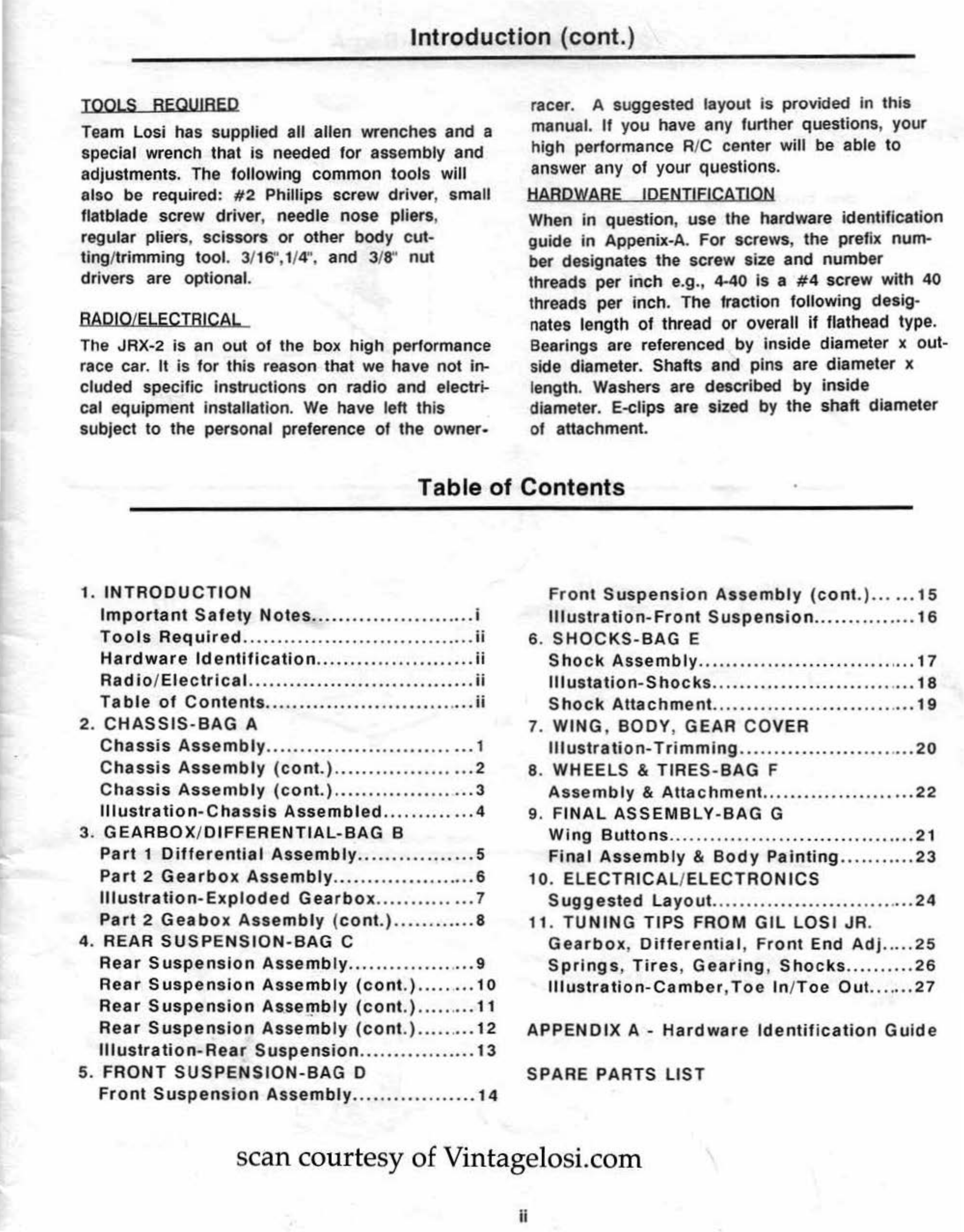
1. Introduction
The JRX-2 kit
is
composed of different bags
marked Bag A through Bag
F.
Each bag contains
all
of
the parts
ne
cessary
to
complete a certain
section
of
the car. It
is
essential that
yo
u open
only one bag at a time and follow the rig
ht
se-
quence, otherwise you will face difficulties in
finding the right part. It is helpful to read the en-
tire instructions for the bag prior to starting as-
sembly. Key numbers (in circles) have been
assigned
to
each part and remain the same
in
the illustration and throughout the intructions.
For your convenience, an actual size hardware
Identification guide
is
included in Appendix A of
the manual. To check a part, hold it against the
silhouette until it is identified. In some cases
extra hardware has been supplied to replace
easily lost parts. When assembling shafts
to
plas-
tic parts, different fits e.g., press, net, loose
have been designed into the parts. To ensure
that parts are not lost during construction, it is
suggested that you work over a towel or mat
to
prevent the parts from rolling away.
IMPORTANT
SAFETY
NOTES
1.
Select an
area
for assembly that Is away from
reach of small children. The parts are small and
can be swallowed by children causing choking
and possible Internal injuries.
2.
The shock fluids and grease supplied should
be kept out
of
childrens reach. They are not
toxic, but were not intended
for
human consump-
tion.
.
3.
Exercise care when using any hand tools,
sharp instruments and power tools during coo-
struction.
4. Carefully read all manufacture warnings and
cautions
for
any glues
or
paints that may be
used for assembly purposes.
Introduction (cont.)
TOOLS
REQUIRED
Team Losi has supplied all allen wrenches and a
special wrench that
is
needed
for
assembly and
adjustments. The following common
to
ols will
also be required:
#2
Phillips screw driver, small
flatblade screw driver, needle nose pliers,
regular pliers, scissors
or
other body c
ut
-
ting/trimming tool. 3/16",1/4
",
and 3/8" nut
drivers are optio
na
l.
RADIO/ELECTRICAL
The JRX-2 is an out of the box high performance
race car.
It
is
f
or
this reason that we have
not
in-
cluded specific instructions on radio and electri-
cal equipment installation.
We
have left this
subject to the personal preference
of
the owner.
racer. A suggested layout
is
provided in this
manual.
If
you have any further questions, your
high performance R/C center will be able
to
answer any of your questions.
HARDWARE IDENTIFICATION
When
in
question, use the hardware identification
guide
in
Appenix-A. For screws, the prefix num-
ber designates the screw size and number
threads per inch e.g
.,
4-40
is
a #4 screw with 40
threads
per
inch. The fraction following desig-
nates length of thread or overall
if
flathead type.
Bearings are referenced by inside diameter x out-
side diameter. Shafts and pins are diameter x
le
ngth. Washers are described
by
inside
diameter. E-clips are sized by the shaft diameter
of attachment.
Table of Contents
1.
INTRODUCTION
Front
Suspension
Assembly
(cont
.)
......
15
Important
Safety
Notes
..........
..............
i
Illu
st
ra
tion-Front
Suspension
...............
16
Tools
Required
..................................
ii 6.
SHOCKS-BAG
E
Hardware
Identification
..
...
.
..
...............
ii
Shock
Assembly
......
.....
...
..........
..
.
.....
17
Bad
io
/
Eiectrical
............................
.....
ii
lllustation
-S
hocks
..............................
18
Table
of
Conten
ts
...........................
.
...
ii
Shoc
k
Attachment
..............................
19
2.
CHASSIS-BAG
A 7. WING, BODY, GEAR
COV
ER
Chassis Assembly
..............................
1
Illustration-
Trimming
......................
.
...
20
C
hass
is
Assembly
(c
ont.)
....................
2 8. WHEELS & TIRES-
BAG
F
C
hassis
Assembly
(con
t.)
........
.
..
.
........
3
Assembly
&
Attachment
......................
22
Illustration
-C
hassis
Assembled
.............
4 9.
FINAL
ASSEMBLY-BAG
G
3.
GEARBOX
/
DIFFERENTIAL-BAG
B
Wing
Buttons
......................
......
........
21
Part
1
Differential
Assembly
..............•..
5
Final
Assemb
ly
&
Body
Painting
.
..........
23
Part
2
Gearbox
Assembly
.
...
..
.
..............
6
10.
ELECTRICAL/ELECTRONICS
Illustration-Exploded
Gearbox
.............
.7 S
uggest
ed
Layout
..........................
.
...
24
Part
2
Geabox
Assembly
(
cont.)
.....
....
...
8
11
.
TUNING
TIPS FROM
GIL
LOSI
JR
.
4. REAR
SUSPENSION
-B
AG C
Gearbox
,
Different
ia
l,
Fro
nt
End
Adj
.....
25
Rear
Suspension
Assemb
ly
............
...
.
...
9
Springs,
Tires
,
Gearing
,
Shocks
..........
26
Rear
Suspension
Assembly
(cont
.)
..
..
..
...
10
Illu
s
tration
-Ca
mber
,
Toe
In
/
Toe
Out.
......
27
Rear
Suspension
As
.
seipbly
(cont
.)
........
.
11
Rear
Suspension
Assembly
(cont
.)
.......
..
12
APPENDIX
A-
Hardwar
e
Identification
Guide
Illustration
-
Bear
Suspension
.................
13
5.
FRONT
SUSPENSION-BAG
D
SPARE
PARTS
LIST
Front
Suspension
Assembly
..................
14
sc
an
courtesy ofVintagelosi.com
ii
2. Chassis Assembly-Bag A
1.
locate
and open Bag
A.
2. Secure side bulkheads (6) to sides
of
chassis
using
four
4-40 X 3/8" flathead screws
(7).
Fig.1
3. Secure
two
aluminum steering posts (13) to
chassis (4) using two 4-40 X 3/8" flathead screws
(
7)
. Fig 2
4. Secure front shock tower {1) to front bulkhead
{2)
using two 4-40 X 3/8" socket head screws
(3). Fig.3
Page 1
C>
..
.,.
_,-
I
J,
I I
(])
FIG. 1
(])
FIG. 2
---
FIG. 3
Chassis Assembly-Bag A (cont.)
5. Insert wing tubes (8)
into
top
of
rear bulkhead
{
9)
as illustrated. *Note: These are a
tight
press
fit.
6. Secure rear
shock
tower (10)
to
front
of
rear
bulkhead
(9)
using
four
4-40 x 3/8" socket head
screws (3).
7. Secure rear bulkhead {9)
to
chassis (4) using
two
4-40 x 3/8" flathead screws (
7)
in front and
two
8-32 x 1/Z' flathead
aluminum
screws (
11
) in
the rear
Page 2
•
I
J
~
0
FIG.
4
Chassis
Assembly-Bag
A
(cont.)
8. Secure front bulkhead (2)
to
front
of
chassis
(4) using four 8-32 X 3/8" long flathead
aluminum
sc
rews
(5
). Fig
.S
9. Secure battery holder (
12
) to chassis (
4)
using
four
8-32 X 1/Z' flathead aluminum screws
(11
).
Fig.6
•
10. Secure antenna mount
(1
4) to right hand side
of
chassis
as
illustrated with a 4-40 X 3/8"
flathead screw (7). Fig.7
11
. Snap antenna cap (112) onto antenna mount.
Fig. 7
0
--
I
I
I I
e ,.
1.----®
®-
Page 3
FIG. 5
FIG. 6
s
FIG. 7
Chassis Assembled
D-.--
@
e--
--
=
Page 4
3.
Part
1-Differential
Assembly-Bag
B
1.
lo
cate and open Bag B. Remove small inner
bag containing differential parts and set
remainder
of
parts aside for
now
.
2.
locate
small white grease container {15) and
open.
3.
Locate differential gear {16) from small bag.
Fig.8
4. Using small instrument such as a toothpick
or
precision screwdriver, carefully dab a minute
amount
of
grease into each bearing hole of the
gear. Keep grease away from gear teeth. Fig.8
FIG. 9
5. Press small ball bearings (17) into greased
holes
of
differential gear (16). Flg.8
6. Insert 1/4" X 3/8" bearing (18) into female half
of
differential (
19
). Fig.9
7. Insert locknut
(20)
into opposite side
of
female differential half (
19)
. Fig.9
8.
Locate
5-4()
X 3/4" button head screw (21) and
build thrust assembly in the following order: Flg.9
a. slide three opposing bellville washers (22) on
screw.
* Note-Bellvilles are slightly coned.
b. one small thrust washer {23)
c. one 5-ball thrust bearing (24)
• Note-Apply liberal amount
of
grease
to
this
part.
d. one small thrust washer (23)
e. Set aside until Step 13.
®
!
0
--
- -
...;..
~'
-
0 0
""'"'=
0 0
0 0
0 0
()
0
~
--of-
+-'\.\~
19
20
FIG. 8
9. Place one hex thrust washer (25) on male half
of
differential (26). Fig.9
10. Place center differential gear on male half
of
differential
(26)
over hex thrust washer (25). Flg.9
11
. Place one hex thrust washer
(25)
on female
half
of
differential gear (
19
). Fig.9
12
. Insert male half
of
differential gear (26) into
bearing
in
female half of differential (
19)
. Fig.9
13. Insert thrust washer screw assembly (from
step
8)
into male half
of
differential
(2
6) and
screw into female half slowly, rotating differen-
tial halves
to
properly seat parts.
DO
NOT OVER-
TIGHTEN
AS
DAMAGE
TO
THE
THRUST
ASSEMBLY
CAN
OCCUR
. Fig
.9
14. Insert a 5/16" x 1/2 ' bearing
(101
) into into
each end of differential assembly. Fig.9
15
. Set differential aside until step
11
in part 2,
Bag B.
Page 5
Pa
rt
2-Gearbox Assembly-Bag 8 (cont.)
1.
Remove remaining parts from lar
ge
Bag B.
2.
Install 3/16" X 3/8'' bearing (27)
into
upper
bearing seat
of
the left half
of
gearbox (28).
Fig.10
3.
Install
two
Smm x
14
mm beari
ngs
(29) i
nto
lower bearing seats
of
the left half
of
gearbox
(28). Fig.9
4. Repeat steps 2 and 3 with the r
ight
side of
gearbox (30).
5.
Install output gear {31)
into
lower bearing seat
of
left half
of
gearbox {28). Fig.12
6.
Slide outdrive spacer {107)
onto
U-joint out-
dr
ive with the flat side away from U-joint. Fig.
12
7.
Install U-joint
outdr
ive (32)
into
outside lower
bearing seat
of
left
half
of
gearbox {28) and turn
until interlocked with output gear
(31
). Fig.12
8.
Secure the
two
toget
her
with a 4-40 X 1/
2"
socket head screw (33) threaded through the
U-
joint outdrive (32)
into
the
ouput
gear
(31
). Fig.12
9.
Repeat Steps 5-8 with the
right
half
of
gear-
box {30). Fig.12
10
. Attach two large 3/16" E-clips (5
4)
to
pinion
shaft assembly (46). Fig.
11
@
-,
@
I
'
®-
-@
I
I
I
FIG.
11
® ,
, FIG. 10
11
. Slide long side
of
p
inion
shaft assembly (46)
through
top
bearing (27) in the
right
half
of
gear-
box (30). Fig.
12
12. Install differential assembly made in Fig. 9 in
ri
ght
half
of
gearbox {30). Locate on boss
provided. Make sure the adjusting screw
(2
1) in
the differential assembly is facing outward so it
accessible for adjusting. Fig.12
13. Assemble the
right
and left gearbox halves
together. Fig.
12
14. Position assembled gearbox against motor
plate (47). Attach
to
motor
plate (47) using three
4-40 X 1 3/
8"
socket head screws (48). NOTE:
Do
not
use the upper forward
hole
at
this
time.
Fig.12
15. Insert 3/
32!
' X 1/2"
pin
(
41
) into hole in pinion
sha
lt
(46). Press
spur
gear (49)
onto
pinion shaft
(46)
carefully aligning
pin
(
41
) with groove in
spur
gear (49). Secure
gear
with 3/16" E;clip
(54). Fig.12
Pa
ge 6
I
®
•
Exploded
Gearbox
Page 7
-"'0
.~
Q)
--
c .c
~
E
Q)
Q)
:::
UJ
·-
UJ
0
<t
!
•
FIG. 12
Part
2-Gearbox
Assembly-Bag B (cont.)
16.
Install 3/
32!
' x 1/Z' pin (41) into pinned ball
(39)
joint so that
it
extends out evenly on both
sides
of
ball. Fig.
13
.
•
17
. Wedge one 3/3Z' x 1/Z' cross p
in
(41) into
one hole
of
the female drive shaft U-jolnt (
50)
.
Fig.14
18
. Using rounded end
of
the TEAM
LOSI
wrench supplied with kit, pry the opposite end of
3/
32!
' x 1/Z' cross pin
(41)
Into remaining hole
in
the drive shaft U-jo
int
(50). Fig.14
19
. Using remaining cross pin (41) in universal
pivot
(39)
repeat this procedure
to
connect
dr
iv
e
shaft (
50)
to
outdrive U-joint (32). Fig.
14
20. While holding rear pivot support (
51)
in
place under rear of gearbox, slide gearbox as-
sembly into rear
of
rear bulkhead (9).Fig.
15
21
. Secure gearbox and rear pivot support to
chassis (4) using four 8-
32
x 1/Z' flathead
screws (11). Fig.15
22. Secure motorplate (47)
to
chassis using a 4-
40
x 1/4" flathead screw (105). Fig
.1
5
23.
Lock gearbox
to
rear bulkhead using a 4-40
x 1 3/4" socket head screw
(5
3) with a #4
washer (
109
) under the head. Fig.15
* NO
TE
: A 4-40. Nylon
nu
t (
88)
will be attached
later
to
secure the gear cover, Along with
the
4-
40
x 1/8" button head screw included in
th
is
kit.
Fig.37 Page 8
I
~
• •
·--
®
FIG.13
FIG. 15
4. Rear Suspension
Assembly-Bag
C
1. Locate and open Bag C.
2. Install 3/8" studded ball
joint
(3
4) pointing
rea
rward in top outside hole
of
rear bulkhead (9)
as shown. Fig.16
3.
Slide
on
one 1/4" ball (36)
over
one 4-40 X
1/2" socket head screw (33). This will create
o
ne
composite ball joint. Fig.
17
4.
Repeat step 3 three more times.
5.
Thread one
compos
ite ball
joint
into
top
ho
le
in side bulkhead (6) so that the ball is on the out-
side and it can just
spin
freely. Fig
.1
7
6. Repeat step 6 using the bottom hole in side
bulkhead (
6)
as shown. Fig.17
7. Thread one composite ball joint into
top
for-
ward hole in
hub
carrier (35) so that the ball is
on the inside and it can just spin freely. * Note:
Hubs are
non
directional. Fig.
18
8. Repeat step 7 using lowest hole on hub car-
rier (
35)
as shown. Fig.18
9.
Install 3/8" studded ball joint (3
4)
in topmost
hole pointing forward in
hub
carrier (35). Fig.
18
Page 9
6.
~
.
t
®
®
--
®
'~
®
--
FIG.16
FIG.
17
FIG.
18
Rear
Suspension
Assembly-Bag
C
(cont.)
10.
Secure shock mount (37)
to
front
of
top
corner hole in rear shock tower (
10
) using a 4-
40
X 3/4" socket head screw (38) threaded from
rear
of
shock tower
to
front. Fig.
19
11
. Place universal pivot (
39)
In rear axle (40)
so that cross pin hole is aligned vertically. Fig.20
12
. Using pliers, push 3/
32
dia. pin (41) through
axle (
40
) and universal pivot (
39
) until pin ex-
tends out evenly on both sides
of
axle (40). Be
sure there is no binding
of
universal pivot (39) in-
side U-jolnt (40). Fig.
20
13
. Pry universal pivot (39) into male section
(
42
)
of
drive shaft using Fig.
14
in
Bag B as a
reference.
14
. Insert two 3/16 X 3/8 X 1/8" bearings (27)
into either side
of
central hole in hub carrier
(3
5). Fig.
21
15
. Slide axle shaft (40) through central hole
in
hub (
35)
as shown. Fig
.21
16.
Slide spacer washer (44) down axle (4
0)
shaft and up
ag
ainst bearing (27). Fig.21
17
. Secu
re
shaft by sliding 1/16" pin (45) into
through hole in axle shaft (
40
) as shown. Flg.21Page 10
I
~
~--
®
FIG.
19
FIG. 20
FIG.
21
Rear Suspension Assembly-Bag C (cont.)
® ®
'
18.
Slide 1/8 X 1.785 hinge pin
(55)
through
hole
in
rear pivot support
(5
1) f
rom
rear
to
front.
Fig.22
19. Once forward end
of
pin {55)
is
loc
ated half
way between pivot
support
{51) and
r~ar
bulkhead (9), slide one end
of
link
(56)
down pin
(55)
to
front of pivot support (51). Fig.22
20. Place 1/8" E-clip
(57)
on forward groove in
pin (55). Fig.
21. Slide one end
of
link
(56) down hinge pin
{55) and
up
against 1/8" E-clip {57). Fig.22
22
. Slide hinge pin (55)
into
rear bulkhead
(9)
so link (56) is secured between 1/8" E-clip
(57)
and rear bulkhead {9). Fig.22
23. Place second 1/8" E-clip (57) on rear
groove
in
hinge
pin
(55)
so
that
link
(56)
is
lo-
cated between front
of
pivot support
and
rear
1/8" E-clip (57). Fig.22
® ®
\ /
@
FIG. 22
24.
Al
ign splines and
gr
ooves
of
drive shaft hal-
ves. Slide male
sec
ti
on (42)
of
drive sha
ft
in
to
the female section (50) that
is
attached
to
gear
box. Fig.23
25. Taking care
not
to
separate t
he
drive sha
ft
,
align the free ends
of
the links (56) on either
side of the hub
{35)
with the hole run
ni
ng
through the
hub
{35) just below the rear axle
{40). Fig.23
26. Slide 1/8 X 1.420" hinge pin (58) t
hr
ou
gh
links (56)
and
hub. Secure
bot
h ends with 1/8" E-
cl
ips
{57). Check for freedom of travel. Fig.23
®
®
/
/
®
Page
11
FIG. 23
Rear Suspension Assembly-Bag C (cont.)
27
. Snap on one end
of
upper trailing link (59)
on
to
upper ball
joi
nt (36) in side bulkhead. Fig.24
28.
Snap free end of upper trailing link (59)
onto
up
per ball
jo
int in hub (35). Fig.24
29.
Orient lower link (
60
) so rib is
on
bottom
and shock mount holes are towards rear. Fig.24
30.
Snap forward end of lower link (60) o
nt
o
lower ball
joint
(36) in side bulkhead (6). Fig
.2
4
31
. Snap rear end
of
lower link (60) onto lower
ball
jo
int (36) in hub carrier
(3
5)
. Assure
freedom
of
movement
Fig.24
32
. Thread an adjustable rod end (61) onto
each end
of
a 1 1/8" turnbuckle (62) taking care
to
note one side of turnbuckle has left hand
thread
s.
Fig.25
33.
Snap one adjustable rod end (61) onto
the
ball joint (34) pointing towards the rear and
secured
to
the rear bulkhead (9). Fig.26
34. Snap free rod end onto topmost ball joint
(3
4)
pointing forward from
the
hub carrier (35).
Fig.26
35.
Refer
to
Tuning Tips for Camber adjustment.
36.
REPEAT
THESE INSTRUCTION
FOR
OP-
POSITE SIDE
OF
C
AR
. Page 12
-·
•
()
@
/
0@
®
/
FIG.
24
FIG.
25
FIG.
26
Exploded Rear Suspension
'
\
•
\
I\
• I
I
--
®
0\
__4
0
;\'~
\ \
I
I
I
I
•
0-
---1
~---
I ----1
L----
1
z
0
-
z
-
...,..
..
r
ClB,.,
a:
I
'<
.:
:?J,
I
I
_,.
of
0 I I
f-
I I
0-
---
t_
j
:E
'c
~f..
,
'
I',
I
',
1 e '
I \ e
~
\
-s'ft
r-
v
/
/
/ •
/
• •
•
\ \
\ \
\ \
\\
\ \ \
\\\
\ \
~
\
\ \
® ) \
I
Page 13
®
\
!
®
'I
'
I
',
I '
I )
I I
I I
, I I
v I
I
I
!'
I
I
''
I
I
I
I I
I
I
I
FIG.37
5. Front Suspension Assembly-Bag D
1. Locate and open Bag D.
2.
Attach one 3/
16
" studded ball joint (
63
) and
studded ball washers (64) in both ends
of
steer-
ing sector arm (65) as shown. Fig.27
3.
Install the 3/8" studded ball (34) into
the
smal-
lest hole on the servo saver (66). Attach the
servo saver (66)
to
the steering sector arm (65)
using a 4-40 X 1/8" shoulder screw (67). *NOTE:
shoulder screw should turn freely in servo saver.
Fig.
27
4. Attach the idler arm (68)
to
the remaining
hole
on
the steering sector arm (65) using a
4-
40
X 1/8" shoulder screw (67). Fig.
27
5.
Slide servo saver (66), idler arm (68), and
steering assembly, down onto steering posts
(
13
) and secure with
two
3/1f/' E-clips (
54
).
Fig.
27
6.
Attach the A-arms (
69)
with the shock mount-
ings forward
to
the front bulkhead
(2)
using the
1/8" X 1.650" hinge pin (70) as shown. Secure
with
two
1/8" E-clips (57). Fig.28
7.
Attach the spindle carrier (71)
to
the A-arm
(69) with the main body pointing upward using a
1/8" X .960 hinge pin (72)
as
shown. Secure with
two
1/8" E-clips (57). Fig.29
•
Page
14
.....
FIG. 27
.....
FIG.
28
.....
.....
.....
.....
FIG.
29
Front Suspension Assembly-Bag D (cont.}
8. Slide front axle (73)
into
large hole in spindle
(74 & 103), as shown making sure king
pin
holes
are aligned vertically. *NOTE: the spindles are
marked left (103) &
right
(74). Fig.30
9. Attach spindle assembly (74)
to
the spindle
carrier (71) using a 1/8" X .690 hinge king
pin
(75). Secure with
two
1/8" E-clips (57). *NOTE:
Letter R & L should face
up
on
spindle arm.
Fig.30
10. Thread a 3/8" studded ball (34)
into
the
to
p
of
the spin
dle
carrier (71). Thread a 3/
16'
'
studded ball (63)
into
each spin
dle
arm (74 &
103). Fig.30
11. Thread an adjustable rod end (61)
onto
each end
of
the 1 1/
2'
'
turnbuckle(
106). *Note:
One end
of
turnbuckle has lett hand threads.
Repeat this step with another 1 1/
2"
turnbuck
le
(106). Fig.25
12. Snap one rod end (61)
onto
end
of
steer
ing
sector arm (65) and free end
onto
steering
spindle arm (74). Fig.31
13. Snap one end
of
the other
tu
r
nbuckle
as-
sembly (106)
onto
top
of
spindle carrier (71) and
the
other
end
onto
lower near corner
of
shock
tower (1). Fig.(31)
14. Thread one 3/16" studded ball (63)
pointing
rearward into lower near corner
of
shock
tower
(1). Secure with 4-40 n
ut
(110) Fig.32
15.
Mount
shockmount
(37)
onto
inside
top
corner hole
pointi
ng forward in
shock
tower
(1)
using 4-40 X 3/4" screw (38) as shown. Fig.32 Page 15
®
•
FIG. 30
FIG. 31
®
-~
®
FIG. 32
Exploded
Front
Suspension
•
--
-------
I
I
I
I
Page
16
\
\
®
•
FIG. 34
6. Shock Assembly-Bag E
1. Snap 1/8" E-clip (57) on shock shaft [rear
(7
6)
, front (84))
into
groove closest to threads.
2. Slide piston (77) onto shaft from grooved end
until
it
rests against E-clip (57).
3. Secure piston (77)
in
place with another E-clip
(57).
4.
Slide shock cartridge (78) over threaded end
and down shaft [rear (76), front (84)] with hex
end toward threads
on
shaft until rounded end
contacts 1/8" E-clip (57).
5. Fill the shock body [front (80), rear (85)] with
shock
oi
l
(7
9) level to the bottom
of
threads.
6. Slide shaft assembly, piston first, into shock
body [front
(8
0), rear (85)].
7. Slowly screw cartridge (78) into shock body
[front (80), rear (85)) allowing excess
oil
to
bleed past threads. Tighten
to
assure proper
seal.
8.
Assure freedom
of
movement
of
piston.
9.
FRONT SHOCKS ONLY -Press shockmount
ball (36) into ball mount (86) and slide ball
mount into shock cup (87). This will create a
lower front shock mount.
10
. Carefully grasp shock shaft [rear {76), front
(84)) with pliers (insulate with rag to prevent
scoring shaft) and thread
into
lower
shock
mount
[rear (81), front (86)].
11.
Slide spring (rear (82), front
(1
04)) over
shock body [rear (85), front (80)) to rest
on
lower shock mount (rear
(8
1)
, front (86).
12
. Insert 4-40 X 3/8" socket head screw (3)
into
larger clamp hole
of
the shock collar (83) and
thread
into
small hole.
13
. With the collar unclamped, slide it down over
top
of
shock body (front
(80)
, rear (85)] and
onto spring [rear (82), front (104)].
14. Compress spring, rear (82), front (104), ap-
proximately 1/4" and secure in place
by
tighten-
ing collar screw (3).
15
. Assure freedom
of
movement
of
piston.
See Fig. 33 on page 18
Page 17

Other manuals for JRX-2

1

Other Team Losi Motorized Toy Car manuals

Team Losi BAJA REY User manual

Team Losi

Team Losi BAJA REY User manual

Team Losi TEN SCTE User manual

Team Losi

Team Losi TEN SCTE User manual

Team Losi Mini Rock Crawler Pro User manual

Team Losi

Team Losi Mini Rock Crawler Pro User manual

Team Losi Mini Desert Truck 1:18 RTR User manual

Team Losi

Team Losi Mini Desert Truck 1:18 RTR User manual

Team Losi Mini-T User manual

Team Losi

Team Losi Mini-T User manual

Team Losi Aftershock User manual

Team Losi

Team Losi Aftershock User manual

Team Losi l8ight Quick start guide

Team Losi

Team Losi l8ight Quick start guide

Team Losi 22-4 twenty two-four User manual

Team Losi

Team Losi 22-4 twenty two-four User manual

Team Losi Double-XT User manual

Team Losi

Team Losi Double-XT User manual

Team Losi 8ight-E 3.0 User manual

Team Losi

Team Losi 8ight-E 3.0 User manual

Team Losi 8IGHT User manual

Team Losi

Team Losi 8IGHT User manual

Team Losi XXTCR Graphite Plus User manual

Team Losi

Team Losi XXTCR Graphite Plus User manual

Team Losi LST 3XL-E RTR User manual

Team Losi

Team Losi LST 3XL-E RTR User manual

Team Losi 22SCT User manual

Team Losi

Team Losi 22SCT User manual

Team Losi Mini-LST User manual

Team Losi

Team Losi Mini-LST User manual

Team Losi Losi Mega Baja User manual

Team Losi

Team Losi Losi Mega Baja User manual

Team Losi XX4 User manual

Team Losi

Team Losi XX4 User manual

Team Losi TEN SCBE User manual

Team Losi

Team Losi TEN SCBE User manual

Team Losi XX User manual

Team Losi

Team Losi XX User manual

Team Losi XXX-SCT User manual

Team Losi

Team Losi XXX-SCT User manual

Team Losi 8IGHT-E 2.0 User manual

Team Losi

Team Losi 8IGHT-E 2.0 User manual

Team Losi MICRO-T User manual

Team Losi

Team Losi MICRO-T User manual

Team Losi XXX-BK2 User manual

Team Losi

Team Losi XXX-BK2 User manual

Team Losi Desert Buggy XL-E 2.0 User manual

Team Losi

Team Losi Desert Buggy XL-E 2.0 User manual

Popular Motorized Toy Car manuals by other brands

Carrera 370402009 quick start guide

Carrera

Carrera 370402009 quick start guide

Peg-Perego RANGER 538 Use and care

Peg-Perego

Peg-Perego RANGER 538 Use and care

Eduard ITALERI quick start guide

Eduard

Eduard ITALERI quick start guide

Traxxas Rally 74076-3 owner's manual

Traxxas

Traxxas Rally 74076-3 owner's manual

Mattel Disney PIXAR THE WORLD OF Cars M6773 instructions

Mattel

Mattel Disney PIXAR THE WORLD OF Cars M6773 instructions

Power Wheels HJL31 owner's manual

Power Wheels

Power Wheels HJL31 owner's manual

ECX Circuit series instruction manual

ECX

ECX Circuit series instruction manual

Traxxas 4810 owner's manual

Traxxas

Traxxas 4810 owner's manual

Redcat Racing Electric RC Vehicle instruction manual

Redcat Racing

Redcat Racing Electric RC Vehicle instruction manual

Power Wheels GNH86 owner's manual

Power Wheels

Power Wheels GNH86 owner's manual

HBX 2098B instruction manual

HBX

HBX 2098B instruction manual

Serpent Viper 977 EVO Instruction manual & reference guide

Serpent

Serpent Viper 977 EVO Instruction manual & reference guide

Kyosho Ultima manual

Kyosho

Kyosho Ultima manual

HYPER TOY COMPANY DRIFTKING3 manual

HYPER TOY COMPANY

HYPER TOY COMPANY DRIFTKING3 manual

Jamara Porsche GT3 RS 2,4GHz instructions

Jamara

Jamara Porsche GT3 RS 2,4GHz instructions

Spinmaster MECCANO EVOLUTION 2 IN 1 instructions

Spinmaster

Spinmaster MECCANO EVOLUTION 2 IN 1 instructions

Carrera RC Ford F-150 Raptor Assembly and operating instructions

Carrera RC

Carrera RC Ford F-150 Raptor Assembly and operating instructions

Horizon Hobby Axial SCX24 B-17 Betty instruction manual

Horizon Hobby

Horizon Hobby Axial SCX24 B-17 Betty instruction manual

manuals.online logo
manuals.online logoBrands
  • About & Mission
  • Contact us
  • Privacy Policy
  • Terms and Conditions

Copyright 2025 Manuals.Online. All Rights Reserved.