manuals.online logo
Brands
  1. Home
  2. •
  3. Brands
  4. •
  5. Team Losi
  6. •
  7. Motorized Toy Car
  8. •
  9. Team Losi XX4 User manual

Team Losi XX4 User manual

Other manuals for XX4

2

Other Team Losi Motorized Toy Car manuals

Team Losi 8ight-E 3.0 User manual

Team Losi

Team Losi 8ight-E 3.0 User manual

Team Losi ROCK REY User manual

Team Losi

Team Losi ROCK REY User manual

Team Losi 22SCT User manual

Team Losi

Team Losi 22SCT User manual

Team Losi mini SCT User manual

Team Losi

Team Losi mini SCT User manual

Team Losi 8IGHT-T 2.0 RTR Truggy Manual

Team Losi

Team Losi 8IGHT-T 2.0 RTR Truggy Manual

Team Losi XXX-SCT User manual

Team Losi

Team Losi XXX-SCT User manual

Team Losi XX User manual

Team Losi

Team Losi XX User manual

Team Losi 8IGHT User manual

Team Losi

Team Losi 8IGHT User manual

Team Losi TENACITY SCT User manual

Team Losi

Team Losi TENACITY SCT User manual

Team Losi XXX-T Sport User manual

Team Losi

Team Losi XXX-T Sport User manual

Team Losi 8IGHT User manual

Team Losi

Team Losi 8IGHT User manual

Team Losi Micro-DT User manual

Team Losi

Team Losi Micro-DT User manual

Team Losi XXX-NT Adam Drake Edition User manual

Team Losi

Team Losi XXX-NT Adam Drake Edition User manual

Team Losi LX-T User manual

Team Losi

Team Losi LX-T User manual

Team Losi Mini-LST2 User manual

Team Losi

Team Losi Mini-LST2 User manual

Team Losi LOS01008 User manual

Team Losi

Team Losi LOS01008 User manual

Team Losi 8ight RTR User manual

Team Losi

Team Losi 8ight RTR User manual

Team Losi Night Crawler LOSB0104 User manual

Team Losi

Team Losi Night Crawler LOSB0104 User manual

Team Losi MICRO 4X4 User manual

Team Losi

Team Losi MICRO 4X4 User manual

Team Losi 8IGHT-XE User manual

Team Losi

Team Losi 8IGHT-XE User manual

Team Losi Raminator User manual

Team Losi

Team Losi Raminator User manual

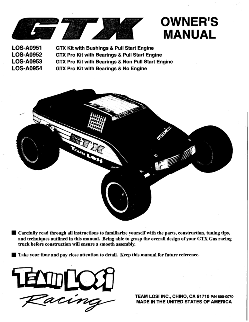
Team Losi LOS-A0951 User manual

Team Losi

Team Losi LOS-A0951 User manual

Team Losi ROCK REY User manual

Team Losi

Team Losi ROCK REY User manual

Team Losi 8IGHT-T 2.0 RTR Truggy User manual

Team Losi

Team Losi 8IGHT-T 2.0 RTR Truggy User manual

Popular Motorized Toy Car manuals by other brands

Reely Dune Fighter 3S operating instructions

Reely

Reely Dune Fighter 3S operating instructions

REVELL 1970 Chevelle SS 454 manual

REVELL

REVELL 1970 Chevelle SS 454 manual

Jamara Mercedes-AMG GLE 63 Instruction

Jamara

Jamara Mercedes-AMG GLE 63 Instruction

Eduard Humber Scout Car Mk.I exterior quick start guide

Eduard

Eduard Humber Scout Car Mk.I exterior quick start guide

Jamara VW T1 Bus Instruction

Jamara

Jamara VW T1 Bus Instruction

REVELL 68 CHEVY CHEVELLE SS 396 manual

REVELL

REVELL 68 CHEVY CHEVELLE SS 396 manual

Schumacher Pro Cat instruction manual

Schumacher

Schumacher Pro Cat instruction manual

Tamiya TT-01 TYPE E instruction manual

Tamiya

Tamiya TT-01 TYPE E instruction manual

Eduard Krupp Protze 6x4 1/48 quick start guide

Eduard

Eduard Krupp Protze 6x4 1/48 quick start guide

New Bright 61072UEP quick start guide

New Bright

New Bright 61072UEP quick start guide

Team Durango DEX410v5 manual

Team Durango

Team Durango DEX410v5 manual

Jamara Mercedes Actros Muldenkipper 2,4 GHz Instruction

Jamara

Jamara Mercedes Actros Muldenkipper 2,4 GHz Instruction

PLAYMOBIL 9536 manual

PLAYMOBIL

PLAYMOBIL 9536 manual

Atomic BZ3 instruction manual

Atomic

Atomic BZ3 instruction manual

Jamara McLaren Senna 2,4GHz instructions

Jamara

Jamara McLaren Senna 2,4GHz instructions

Aiyaplay 370-290V00 user manual

Aiyaplay

Aiyaplay 370-290V00 user manual

ZEROTRIBE Zetricks ZT1144 instruction manual

ZEROTRIBE

ZEROTRIBE Zetricks ZT1144 instruction manual

INJUSA 412 Assembly instructions

INJUSA

INJUSA 412 Assembly instructions

manuals.online logo
manuals.online logoBrands
  • About & Mission
  • Contact us
  • Privacy Policy
  • Terms and Conditions

Copyright 2025 Manuals.Online. All Rights Reserved.

11/J
Carefully
read
through
all instructions to familiarize yourself
with
the
parts, c;onstruction,
tuning tips,
and
techniques outlined in this
manual
. Being able to
grasp
the
overall
design
of
yo
ur
:X:X-4
4WD off-
road
car
before construction
will
ensure
a
smooth
assembly.
11/J
Take
y
our
time
and
pay
close attention
to
detaiL
Keep
this
manual
for future reference.
TEAM
LOSI,
INC
., CHINO,
CA
91710 PIN 800-0087
MADE
IN
THE
UNITED STATES
OF
AMERICA
Scan provided by vintagelosi.com
WELCOME
XX-4
OWNER!
Thank
you for selecting Team Losi and the XX-4 as your new off-road racing vehicle.
As
you will soon see,
we
have
made every effort
to
produce a kit that
is
not only the most competitive,
but
easy to build and maintain as well.
The
simple bag-by-bag assembly sequence and unmatched easy-
to
-
fo
ll
ow instructions, combined with T
ea
m Losi's famous
qualit
y-
fitting parts, should make building your XX
-4
an
enjoyable project.
Before you open a bag
or
start any assembly, please take a
few
moments
to
read completely
thr
ou
gh
the following
instructions. This will familiarize yourself with
not
only the various parts,
but
the tools you
will
need
as well.
Once
again, thank you for choosing Team Losi.
Good luck and good racing!
1.
INTRODUCTION
XX-4 COMPLETED KIT DIMENSIONS
Front Width: 9-5/8" Rear Width:
9-7
/
8"
Height:
5.75"
Ove
raH
Length: 1
5-112"
Whee
lbase:
10
-3/4" All dimensions at ride height.
We
ight will vary depending
on
accessories.
NOTES &
SYMBOLS
USED
mal
This is a common figure numberfound
at
the beginning
of
each new illustrati
on
throughout the manual.
0 Step
I.
-Each step throughout the entire manual has a
check box to the left
of
i
t.
As
you complete each step, mark the
b
ox
with a check. Ify
ou
need to take a break and return to build-
ing at a later time you will be able to locate the exact step where
you le
ft
ofT.
~N
OTE:
This
is
a common note. Itis used to call attention to
specific deta
il
s
of
a
ce
rtain step in the assembl
y.
it,
IMPORTANT
NOTE: Even ifyou are familiar with
Team Losi
ki
ts,
be sure and pay attention to these notes.
They
point out very importantdetails during the assembly process. Do
n
ot
ignore these
not
es!
~
:>
This wrench designates a performance tip.
Th
ese tips
are
n
ot
necessary,
but
can improve the performance
of
your
XX
-4c
ar.
~
In illustrations where it is important to note which
direction parts are pointing, a helmetlike this onewill beincluded
in
the illustration. The helmetwill always face the front
of
the car.
Any reference to the right
or
leftside will relate to the direction
of
the helme
t.
KIT/MANUAL ORGANIZATION
Th
e XX-4
is
composed
of
different bags marked A through H.
Each bagcontains all
of
the parts necessary to completea particu-
larsection
of
the
XX
-4 car. Some ofthese bags have subassembly
bags within the
m.
It is essential that you open only one bag
at
a
time and
foHow
the correct assembly sequence, otherwi
se
you
may face difficulties in finding the correct part. It
is
helpful to
re
ad
through the instructions for
an
entire bag priorto beginning
assembl
y.
Key numbers (in parenthesis) have been assigned to
each part
an
d remain the same throughout the manual. In some
illustrations, parts which havealready been installed are
not
shown
so that the currentsteps can be illustrated more clearly.
For your convenience,
an
actual size hardware identification
guide
is
included with each step.
To
check a part, hold it against
the silhouette until the correct part
is
identified. In some cases
extra hardware has been supplied for
par
~ that may be easy to
lose.
The
molded parts in the
:XX
-4 are manufactured to demand-
ing tolerances. When screws are tightened to the point of being
snug, the parts are held firmly in place. For this reason it
is
very
important that screws
not
be overtightened in any
of
the plastic
parts.
To
insure that parts are not lost during construction, it
is
rec-
ommended that you work over a towel.
or
mat
to prevent parts
from rolling away.
IMPORTANT SAFETY NOTES
I.
Select an area for assembly that
is
away from the reach
of
small childre
n.
The
parts
in
the
kit
are
smalland
can
be
swallowed
by
children,
causing
choking
and
possible
internal
injury.
2.
The
shock fluid
and
greases suppliedshould bekeptout
of
children's reach.
They
are
not
intended
for
human
consumption!
3.
Exercise
care
when using
any
hand tools, sharp instruments,
or
power tools during construction.
4.
Carefully
read
all
manufacturer's
warnings
and
cautions
for any
glues, chemicals,
or
paints that may be used for assembly and
operating purposes.
TOOLS REQUIRED
Team Losi has supplied all necessary Allen wrenches
and
a special wrench that
is
needed for assembly and adjustments.
The
follow-
ingcommon tools
will
also berequired: Needle-nose pliers, regular pliers, hobby knife, scissors
or
otherbodycutting
/t
rimming tools,
and a soldering iron may be necessary for radio installation.
3/
16
", 1/4", and 3/8"
nut
drivers are optional.
RADIO
/EL
ECTRICAL
A suggested radio layout
is
provided in this manual. Your high-performance
RIC
center should be consulted regarding spec
ifics
on
radio/electrical equipment.
HARDWARE IDENTIFICATION
When in question, use the hardware identification guide
in
each step. For screws, the prefix number designates the screw size
and
number ofthreads
per
inch (i.e. 4-40
is
#4
screw with 40 threads
per
inch).
The
second number
or
fraction designates the length ofthe
screw. For cap-head screws, this
number
refers to the length ofthe threaded portion
of
the screw. For flat-head screws, this number
refers to the overall length
of
the screw. Bearings
and
bushings are referenced by the inside diameter x outside diameter. Shafts and
pins are diameter x length. Washers are described by inside diameter or the screw size that will pass through the inside diameter.
E-clips are sized by the shaft diameter that they attach to.
MOTORS AND GEARING
Th
e XX-4 includes an
84
-tooth, 48-pitch spur gear.
The
overall internal drive ratio
of
the XX-4 is 2.3:
I.
Th
e piniongear that
is
used
will
determine the final drive ratio.
To
calculate the final drive ratio, first divide the spurgear size bythe pinion gearsize. Forexample,
ifyou
are
using a 20-tooth pinion gear, you would divide 84 (spurgear size) by
20
{p
inion gearsize). 84120 = 4.2. This tells you that
4.2
is
the externaldrive ratio. Next, multiply the internal drive ratio (2.
3)
by the external drive ratio{in this case
4.2)
.2.3x 4.2 = 9.
66
.
This means that by using a
20
-tooth pinion gear with the standard 84-tooth spurg
ea
r, the final drive ratio is 9.66:
I.
Consult your high-performance shop for recommendations to suit your racing style
and
class.
The
chartbelow lists some
of
the
more common motor types
and
a r
ec
omm
ended initial gearing for that motor. Ratios can be adjusted depending
on
vario
us
track
layouts, tire sizes,
and
battery types.
RECOMMENDED INITIALGEARING FOR COMMON MOTORS
TYPE
OF
MOTOR PINION
24° Stock
24
-
25
36
° Stock 22-23
10-
Turn
Modified
16
11-
Turn
Modified
17
12-Turn Modified
18
13
-
Turn
Modified
19-21
14-
Turn
Modified
20-21
15-Turn
Modified
22
16-Turn
Modified
23
Scan provided
by
vintagelosi.com
TABLE
OF
CONTENTS
SPUR
84
84
84
84
84
84
84
84
84
1.
INTRODUCTION
.............
......
..
......
....
..............
....
..
.i 3.
BAGB
..........
..
................
..
...
..
.........
..
...............
..
5-10
Completed Kit Dimensions .
........
.......
....
...
...................i 4. BAG C..........
..
.........
..
...
....
..
.............
..
..........
....
11-18
Not
es
&Symbols .............................. .
.. ..
..
...
.
..
.
....
.
..
.i
5.
BAG D
..
.....
..
.......
..
........................
..
.........
..
...... 19-24
Kit Manual Organization
.......
.
..
. .
....
.
....
..
..
....
............i 6.
BAG
E ............................................................. 25-29
Important
Sa
fety Notes
......
.
...
.
..
. .
....
..
.
......
.
....
.......
..
i
7.
BAG F ...........................................................
..
30-33
To
ols Required
..
....
..............................
....
......
....
....
ii
8.BAGG
.
..
....
..
.
..
....
..
...
..
..
........................................
34
Radio/Electrical...................................................
..
..
.
...
ii 9. BAG H
....
...................
..
..........................
....
..
.
..
. 35-40
Hardware Identification.........
..
.
..
...
..
.
....
.
....
. .
....
. .ii 10. Tips from the Team
..
..
............................
..
......
..
41-43
Recommended Gearing ..................
....
.
......
.
........
......
ii
11. Spare Parts ..................................................... 44-
47
2. BAG A ....
......
.......................................................1-4
12
. Glossary ...........
..
................
....
...............
....
..........
47
Team
L
os
i
is
co
ntinually
changing
and
improving
designs
;
therefore
, tM
actual
part
ma
y
appear
slightly
diffirent
than
the
illustrated
part.
1/lustra
.
tions
of
par
/J
and
=nrtMu>
may
be
slightly
d
istor
ted
to
e
nhan
ce
ptrtinent
details
.
ll
BAGA
D Step I. Press a .078" x
318"
spiro!
pin
(I) into
the
outer
hole
in
eac
h
end
of
the layshaft{2).
Center
the
pins {I)
in
the shaft
(2
)
so
that
they
extend evenly
from
both
sides
of
the shaft (2).
*NOTE:
The
.078"x 3/B"pins
are
the
two
long
spirol
pinsfound
in
bag
A.
There
is
also
a
shorter
spirol
pin
which
will
be
used
in
step
4.
The
layshaft
has
three
holes
in
it
and
no
threads
on
the
end.
D
Step
2. Place
the
large (42 tooth)
2mm
belt pulley (3)
over
the
end
of
the layshaft (2) farthest away from the
center
hole.
Align
the
pin
(I) with the slot
in
the pulley (3)
and
press the
pulley{3)
over
the
pin
(I). Securethe
pulley
(3) to the layshaft{2)
w~h
a 3/
16"
C-clip {4).
D
Step
3. Attach
the
small (
17
tooth}
3mm
belt
pulley
(5)
to
the
open
end
of
the layshaft{2). Align the
pin
(I}with the slot
in
the
pulley {5)
and
press the
pulley
{5)
over
the
pin
(1). Secure the
pulley (5}
to
the layshaft(2}with a
3/16
" C-clip (4).
D
Step
4. Press the .078" x 51
16"
spiro!
pin
(6
) into the
hole
farthest from the
groove
in the slipper shaft (7).
Center
the
pin
{6) in the shaft (7) so
that
the
pin
(6)
extends
evenly from
both
sidJ!S
of
the shaft(7).
D
Step
.5.
Thread
the 5-40 x 51
8"
set
screw (8) all
the
way into
the
end
of
the slipper shaft {7).
This
is easiest accomplished
by
inserting the
1116
" Allen wrench (9) into the
open
hole
in
the
shaft (7}
to
hold
it
in
place while tightening
the
set
screw (8).
.&.
IMPORTANT NOTE:
The
pin
must
be
centered
in
the slippershaft.
~
::>
A small
amount
of
liquid thread-lock will
hold
the
set
screwsecurely
in
place.
1
Figure
7
Figure
2
BAG A
(Continued)
Figure
3 0
@@@0
@ @
@@
0 Step6. Slide the frontslipper
back
plate(
10
)
over
the
end
of
the
slipper
shaft
(7)
with
no
flat spots.

While
aligning the pin
(6)
in the
shan
(7)
with
the
slot
in
the
back plate (
10),
press
the
back
plate (
10)
all
the
way against the
pin
(6).
0 Step
7.
Place the front(yellow) slipper
pad
(
II
)
on
the side
of
the
spur
gear
(
12
)
and
align the notches
on
the
spur
gear
(
12
) with the
notches in
the
slipper
pad
(
11
).
0
Step
8. Place
the
spur
gear
/slipper
pad
assembly,
pad
side
first,
on
the
slipper
shaft (7). Slide
the
assembly all the way across
the
shaft, against the
back
plate{
10
). Ensure
that
the
slipper
pad
(
II
)
and
spur
gear
(
12
)
are
still
properly
aligned.
0
Step
9.
Position
the
rear
(
dark
-
colored
)
slipper
pad
(
13
)
over
the
slipper
shan
(7) against
the
exposed
side
of
the
spur
gear
(
12
). Be
certain that the notches
in
the slipper
pad
(
13
) align with
the
notches
on
the
spur
gear
(12).
0 Step
10.
Align
the
three
posts
on
the
29
-tooth
2mm
beltpulley (
14
) with
the
three holes
in
the
rear
slipper backplate(
15
).
Press the
pulley (
14
) flush against
the
back plate (
15
).
Slide the
pulley/back
plate assembly, back plate (
15
) first,
over
the slipper s
han
(7)
and
against
the
r
ear
slipper
pad
(
13
).
:J o
If
there
is
any
flashing (three smaH points)
present
on
the
outside surface
of
the pulley,
it
should
be
cut
ofT
before conti
nu
·
ing. Flashing is rarely present,
but
if
it exists it could
make
alignment
of
parts in the
upcoming
steps
more
difficult.
0 Step II. Place
the
pulleyflange
(16)
next
to the pulley (
14
}
and
center
it
over
the shou
ld
er
on
the pulley (
14
}.
Th
e side
of
the flange
(
16
) with the ring
cut
in
it
should
face
away
from the pulley (
14
).
0
Step
12.
Position
one
of
the
two slipper thrust washers (
17
)
next
to the pulley flange (
16
}.
Center
the
thrust washer
so
that
it
sits
over
the
shoulder
on
the
pulley {
14
}. Slide
the
slipper
thrust
bearing
(
18
)
over
the
slipper
shan
(7),
next
to
the
thrust washer (
17
),
foUowed
by
the
second
thrust
washer (
17
). ·
0
Step
13.
Slide
the
thrust
bearing
spacer
(
19
), small flange
side
first,
down
the
shan
(7)
next
to
the
outer
thrust washer (
17
).
The
small flange
on
the
spacer
(
19
) shouldfit into the
center
of
the
outer
washer (
17
)
and
the thrust
bearing
(18)
so
that the large
portion
of
the
spacer
(
19
) rests flush against
the
outer
washer (17}.
0 Step
14.
Pl
ace
a3/16" x 31
8"
bearing
(20)
next
to the thrust
bearing
spacer
(
19
).
Slide the small plastic
bearing
washer
(2
1)
over
the
set
screw (
8)
in
the shaft (7) so
that
it rests against the
bearing
(20).
WOTE:
If
till 3fl6"x
318"
bearing
only
has
one
Tefom
~
seal
(tan,
woven
looking)
in
it,
position
the
seal
to
till outside-
away
from
the
spur
gear.
0 Step 15. Stack the four
118"
Belleville washers (22)
in
opposing
directions
as
sho
wn
in
Figure
3A
so
that
the
small
side
of
the first
washer
(
22
) rests against
the
bearing
washer
(2
1).
The
small
side
of
the fourth washer (22) should face
the
outside
of
the
assembly.
0 Step
16.
Thread
the 5-40locknut (
23
)
onto
the
set
screw (8)
by
hand.
In
sert the 1/
16"
Allen
wrench
(9) into the
open
hole in the
shafi (7
).
Ti
ghten
the
nut
(
23
) until it
just
touches
the
outside Belleville
washer
(
22
). this point, tighten the
nut
{
23
)
one
full
tum
(360"
).
This
should
be
a
good
starting
point
for
the
slipper adjustmenL
Figure
3A
Figure3
2
BAG A
(Continued)
0 Step
17.
Snapa 3/
16"
C-clip (4) into the groove in the center
of
th
e slippershaft (7).
0 Step
18.
Place a 3/
16"
x 3/8'' bearing (20)
over
the shaft (7),
next
to
the C-clip (4).
"NOTE:
If
the
3116"
x
318
"
bearing
only
has
one
Tiflon
"
seal
(tan,
wovm
looki11g}
in
it,
position
the
seal
to
the
outside
-
away
from
the
center
of
the
shaft.
0 Step
19.
Slide the
one
-way/clicker pulley flange (
175
}
over
the shaft {7) so that
the
small shoulder rests against the bearing
(20). Place the
one
-way/clickerpulley (
24
)
over
the shaft(7),
next
to the flange (
175
}so that the splines
on
the
pulley (24) are to the
outsid
e.
0 Step 20. Apply white thrustbearing/assembly grease{49)
to
the
splined surface,
as
well as the inside,
of
the one-way/clicker
plate (25). Align the flat sections
on
the
one
-way/clicker plate
(25) with the flat sections
on
the shaft (7). Place the one-way/
clicker plate (25)
next
to the one-way/clicker puHey {24}, align-
ing the teeth
on
both parts.
0 Step
21.
Center the
one
-way adjustment spring (26)
on
the
end
of
the one--wayIclicker plate (25). Position the adjustment
spring washer (27), small side fust,
over
the shaft (7)
and
in
the
end
ofthe
spring (26).
0 Step 22.
Thread
the
4--40
mini locknut (28)
onto
the
end
of
the shaft(7). Tighten the
nut
(28) all the way, then back itofftwo
full turns {360" x 2). This should be a good initial adjustment.
mm2
*Refer to page 1 of Addendum for
WE
XX4
0 Step 23. Place a short
2mm
drive belt (29}
over
each
of
the
pulleys (
14
), (24).
0 Step24. With the belts {29) in place, install the slippershaft
assembly in the forward area
of
the chassis (
30
) with the
spur
gear
(
12
) to the right side
of
the chassis (
30
).
l:ai
@I@
*Refer to page 1 of Addendum for
WE
XX4
® ® ®
0 Step 25. Apply a small
amount
of
white thrust
bearing/
assembly grease (49) to the belt roller shaft (32)
and
center th.e
belt roller (
31
) on the belt roller shaft(
32
).
0 Step 26. Place a
3/32"
shim (
33
) over each
end
of
the
belt
roller shaft (
32
}.
.
;,
0 Team
Losi
offersa bearingbeltroller kit (A-6912). This
kit replaces
the
bushing belt rollers in the kit with small ball
bearings.
@
Figure
4
Figure
5
Figure
6
3
BAG A
(Continued)
*Refer to page 1 ofAddendum for WE XX4
0 Step
27.
Carefu
ll
ypick
up
thebeltrollerassemblyusinga pair
of
tweezers
or
small needle-nose pliers.
Ho
ld
the
assemblyby the
shims (
:3:3
) on either end as shown. Position the assemb
ly
above
the
area
fo
r the shaft(32) in the chassis (30). This
area
is
located in
the
center
of
the chassis (
30
), directly behind the vertical rib.
0 Step28.
Once
the
assemblyis in position, press
the
shaft {
32
)
into place.
WOTE:& ((lriful
nollo
bnuJ
or
damage
tlu
shims.
17te
rolkr
should
rotate
fruly
once
in
position.
@
@
0 Step 29. Pressa3/16" x
318
" bearing(
20
) into the rightlayshaft
bearing insert (
34
).
The
right bearing insert (
34
)
is
the
one
with
th;
small notch in the bottomcomer.
0 Step 30. Place
the
right bearinginsertassembly
over
the
end
ofithe layshaft (2) with the large pulley.
0 1Step 31. Press a
3/
16" x
3/8"
bearing
(20)
into the leftlayshaft
bearinginsert
(35}
. Place the leftbearinginsertassembly over the
other
end
of
the layshaft
(2)
.
1J
Step 32.Wrap
the
rear drive belt(
36
) around the smallpulley
(5}
;nd
hold the b
elt
(36) tightly around the pulley
(5).
0 Step 33.
Hoo
k
the
sidedrive belt (29) around the large pulley
(3)
.
0 Step 34. Rotate the bearing inserts (34), {
35
) so that
the
fiat
edges faces down
and
the tabs
are
to
the
rear. Press the layshaft
assembly -with belts around the pulleys -into position in
the
chassis (
30
).
The
rear belt(
36
) should run between the centerribs
of
the
chassis (
30
}. Ensure
that
both bearing inserts (
34
), (
35
)
are
all the way down
in
the chassis (
30
}.
WOTE:
17te
top,
exposed
end
of
both
btaring
inserts
should
be
rounded.
4
Figure
7
Figure
8
notch is
on
the
'-..::~,.----ri
g
l
ht-~;ide
bearing ih
se
rt.
F
igure
9
BAGB
@
[J
Step
I.
Insert a 4-40 mini lock
nut
(28) into the
hex
area
of
the
diff
nut
carrier (37).
The
thread-locking portion
of
the
nut
(28) should face
the
outside.
@
@
[J
Step 2. Locate the 5/64" Allen wrench (9)supplied with
the
kit. Place
the
diff
nut
carrier (
37
),
nut
side flfSt, over the Allen
wrench.
[J
Step 3. Stack the six 1/8" Belleville washers (22)
over
the
wrench, next to the diff
nut
carrier (37).
The
washers (22) should
all pointthe same direction and
open
away from the
nut
carrier
(37) as shown in Figure
llA.
[J
Step 4. Place the difftube (
38
)
over
the
wrench, bigside first,
so that the tube (
38
) rests against
the
Belleville washers (22).
@
[J
Step 5. Insert all
of
the parts that
are
stacked on the wrench
intoone
of
the
steeloutdrive/diffhalves (
39
). Line
up
the
tabs on
the
diff
nut
carrier {
37
) with the slots in
the
outdrive (
39
). Make
certain that the diff tube (
38
) is pressed all the way into the
outdrive/diffhalf(
39
),
and
that the tube (
38
)
is
straight.
There
is
a small shoulder on the diff tube (
38
) that should be flush with
the
outersurface
of
the outdrive (
39
).
m.EI
[J
Step 6. Apply a small amount
of
diffgrease (40){clear)to
the
outside ring
of
the
outdrive {
39
). Attach a
diff
drive ring (
41
) to
the outdrive (
39
)
by
lining
up
the slot
in
the ring(
41
) with the slot
in
the
outdrive (
39
).
"'NOTE:
The
diff
grease
is
th
eckar
grease-
not
the
white
colored
grease.
Only
a
smaU
amount
of
grease
is
needed.
It
is
only
there
to
hold
the
drive
ring
in
pW.ce.
& I
MPORTANT
NOTE:
Do
not
glue
the
drive rings to
the outdrive/
cliff
halves. Doing so may
not
allow the washers to
mount
flat.
5
Figure
17
Figure
70
38
22
F=
Hl
""''
A
bttJ
//////
ld
Belleville woshefs shOuld
face
this
d~ecliOn
Figure
77A
Figure
72
Figure
73
BAG B
(Continued)
0 0
@ @
0 Step
7.
Insert a
5mm
x 8mm bearing (42) into the center
of
the rear
cliff
pulley (43).
0 Step
8.
Pressa 3/32"diffball (
44
) into each
of
thesmall holes
in the
cliff
pulley (43).
0 Step 9. Apply a fairly heavy
coat
of
cliff
grease (40) to the
exposedside
of
the drive ring (
41
) that
is
already attached
to
the
outdrive (
39
).
0 Step
lO.
Carefullyplacethe
cliff
pulley (43) overthedilftube
(
38
) so that the diffbaUs (44)
and
cliff
pulley (43) restagainst the
greased drive ring (
41
).
&
IMPORTANT
NOTE
:
ll
is
agood ideato holdthe
cliff
nut
carrier in place so that when installing the pulley, the diff
tube isn't moved.
00
® @
0 Step II. Insert a
5mm
x
8mm
bearing(42) into the second
outdrive/
dilfhalf
(
39
). Make sure.that the bearing(42)
is
pushed
all the way into the outdrive (
39
).
The
handle
of
a hobby knife
(with the blade removed)
or
a pencil can be used
to
push the
bearing (42) into place.
0 Step
12.
Drop the 1/
4"
x 5/
16
" shim (
45
) into the outdrive
(
39
), on top
of
the
5mm
x 8mm bearing (42). Make sure that the
shim (45) sits flat against the bearing (42).
'WOTE:
Be
extra
careful
not
to
bend
tlu
shim!
Figure
74
Figure
76
6
Figure
75
BAG B
(Continued)
©
@ ®
0 Step
13.
I..<>cate
the
diff adjusting screw (46)
and
place the
foam thrustbearing seal (47) over the shoulder
of
the screw (
46
).
0 Step
14.
Place one
of
the 3
mm
x
8mm
raced thrust bearing
washers
(4
8) over the diff screw
(46)
so that
the
groove in the
washer (48) faces up.
0 Step
15.
Using
the
whitethrustbearing/assemblygrease (49),
liberallygrease the thrustwasher(48) and place
the
3
mm
x
8mm
thrust bearing (
50
) over the screw {46),
and
next to the washer
(48). Apply white thrust bearing/assembly grease (
49)
to the ex-
posedside
of
the thrust bearing
(5
0)
and
place
the
second thrust
bearing washer (48) over
the
screw (46), against the thrust
bear
-
ing
(5
0). This time, the groove
in
the thrust washer (48) should
face down.
*NOTE:
Th
e
thrust
bearing/assembly
grease
is
the
white
cowred
grease
-
not
th
e
clear
grease.
0 Step
16.
Very carefully insert the diff screw (46), with
the
thrust bearing assembly installed, into the outdrive (39).
Be
ex-
tremely careful not to
bend
or
pinch the shim (45) while insert-
ingthe diffscrew (
46
). Pull the threaded
end
of
the
diffscrew (46)
w1til
the thrust bearing assembly rests against the shim (45),
next
to the bearing(42) inside the outdrive (
39
).
0 Step
17.
I..<>cat
e the smallest
of
the supplied Allen wrenches
(9) and place
it
in
the slot in the outdrive (39) containing the diff
screw{46).Slide thewrenchall thewayinto the slotin the outdrive
(3
9) against
the
screw {
46
). Handling
the
outdrive (39) with
the
wrench inserted, will hold the diffscrew (46) in place while fin-
ishing assembly
of
the diff.
0 Step
18.
Apply a small amount ofclear
<lifT
grease (40) to the
outer ring
of
the outdrive (
39
). Install the second drive ring(
41
),
again aligning the slots
in
the outdrive (39)
and
the drive ring
(
41
).
~N
OTE:
The
diff
grease
is
the
clear
grease
-
not
the
white
cowred
grease.
Onl
y a
small
amount
of
grease
is
needed.
It
is
only
there
to
hold
th
e
drive
ring
in
place.
0 Step
19.
Apply a fairly
hea
vy coat
of
clear
difT
grease (40)
to
the exposed side
of
the drive ring (
41
).
:J
~
For best results, clean the drive rings with rubbing
al
-
cohol
or
motor spray before
app
lying the grease to the exposed
side.
7
Figure
77
Figure
78