TEC MA-600 Series User manual

TEC Electronic Cash Register
MA-600 SERIES
Owner's Manual
Patersstraat 106-108
2300 Turnhout
Tel:014/42.55.99
info@vanmechelen.be
www.vanmechelen.be
webshop.vanmechelen.be

CE Compliance (for EU only)
This product complies with the requirements of EMC and Low Voltage Directives including their
amendments.
CE- Konformität (nur für EU)
Dieses Produkt entspricht den Anforderungen EMC und Niederspannungs-Richtlinien inclusive
deren Ergänzungen.
Homologué CE
Ce produit répond aux of EMC en matière de courant basse tension.
The socket-outlet shall be installed near the equipment and shall be easily accessible.
Die Ausgangsbuchse sollte leicht erreichbar in der Nähe des Gerätes installiert werden.
Le socle de prise de courant doit être installé à proximité du matériel et doit être aisément
accessible.
La toma de corriente deberá estar instalada cera del equipo y en un lugar de tácil acceso.
Schallemission : unter 70 dB (A) nach DIN 45635 (ISO 7779)
CAUTION!
1. This manual may not be copied in whole or in part without prior written permission of TOSHIBA
TEC.
2. The contents of this manual may be changed without notification.
3. Please refer to your local Authorised Service representative with regard to any queries you
may have in this manual.
Copyright © 2005
by TOSHIBA TEC CORPORATION
A
ll Rights Reserved
570 Ohito, Izunokuni-shi, Shizuoka-ken, JAPAN
< For EU Only >
TOSHIBA TEC Europe Retail Information Systems S.A.
Rue de la Célidée 33 BE-1080 Brussels

Safety Summary
EO1-11154
(i)
Safety Summary
Personal safety in handling or maintaining the equipment is extremely important. Warnings and Cautions
necessary for safe handling are included in this manual. All warnings and cautions contained in this manual
should be read and understood before handling or maintaining the equipment.
Do not attempt to effect repairs or modifications to this equipment. If a fault occurs that cannot be rectified
using the procedures described in this manual, turn off the power, unplug the machine, then contact your
authorized TOSHIBA TEC representative for assistance.
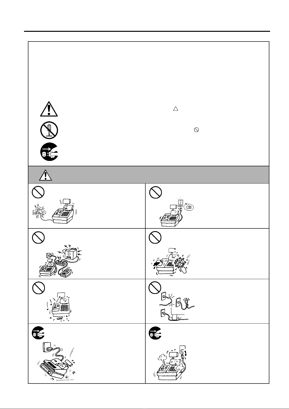
Meanings of Each Symbol
This symbol indicates warning items (including cautions).
Specific warning contents are drawn inside the symbol.
(The symbol on the left indicates a general caution.)
This symbol indicates prohibited actions (prohibited items).
Specific prohibited contents are drawn inside or near the symbol.
(The symbol on the left indicates “no disassembling”.)
This symbol indicates actions which must be performed.
Specific instructions are drawn inside or near the ●symbol.
(The symbol on the left indicates “disconnect the power cord plug from the outlet”.)
This indicates that there is the risk of death or serious injury if the
machines are improperly handled contrary to this indication.
Do not plug in or unplug the
power cord plug with wet
hands as this may cause
electric shock.
Do not use voltages other than the
voltage (AC) specified on the
rating plate, as this may cause fire
or electric shock.
If the machines share the same
outlet with any other electrical
appliances that consume large
amounts of power, the voltage
will fluctuate widely each time
these appliances operate. Be
sure to provide an exclusive
outlet for the machine as this
may cause fire or electric
shock.
Do not place metal objects or
water-filled containers such as
flower vases, flower pots or mugs,
etc. on top of the machines. If
metal objects or spilled liquid enter
the machines, this may cause fire
or electric shock.
Do not insert or drop metal,
flammable or other foreign
objects into the machines
through the ventilation slits, as
this may cause fire or electric
shock.
Do not scratch, damage or modify
the power cords. Also, do not
place heavy objects on, pull on, or
excessively bend the cords, as this
may cause fire or electric shock.
If the machines are dropped or
their cabinets damaged, first
turn off the power switches and
disconnect the power cord
plugs from the outlet, and then
contact your authorized
TOSHIBA TEC representative
for assistance. Continued use
of the machine in that condition
may cause fire or electric
shock.
Continued use of the machines in
an abnormal condition such as
when the machines are producing
smoke or strange smells may cause
fire or electric shock. In these
cases, immediately turn off the
power switches and disconnect the
power cord plugs from the outlet.
Then, contact your authorized
TOSHIBA TEC representative for
assistance.
W
ARNING
Any other than the
specified AC voltage is
prohibited.
Prohibited
Prohibited
Prohibited
Prohibited
Prohibited
Disconnect
the plug.
Disconnect
the plug.

Safety Summary
EO1-11154
(ii)
If foreign objects (metal
fragments, water, liquids) enter
the machines, first turn off the
power switches and disconnect
the power cord plugs from the
outlet, and then contact your
authorized TOSHIBA TEC
representative for assistance.
Continued use of the machine in
that condition may cause fire or
electric shock.
When unplugging the power cords,
be sure to hold and pull on the plug
portion. Pulling on the cord portion
may cut or expose the internal wires
and cause fire or electric shock.
Ensure that the equipment is
properly grounded. Extension
cables should also be grounded.
Fire or electric shock could
occur on improperly grounded
equipment.
Do not remove covers, repair or
modify the machine by yourself.
You may be injured by high
voltage, very hot parts or sharp
edges inside the machine.
Unauthorized modification is
prohibited.
This indicates that there is the risk of personal Injury or damage to objects if
the machines are improperly handled contrary to this indication.
Precautions
The following precautions will help to ensure that this machine will continue to function correctly.
●
Try to avoid locations that have the following adverse conditions:
* Temperatures out of the specification * Direct sunlight * High humidity
* Shared power source * Excessive vibration * Dust/Gas
●
Do not subject the machine to sudden shocks.
●
Do not press the keys too hard. Keys will operate correctly if they are touched lightly.
●
Clean the cover and keyboard, etc. by wiping with a dry cloth or a cloth soaked with detergent and
wrung out thoroughly. Never use thinner or other volatile solvent for cleaning.
●
At the end of the day, turn the power OFF, then clean and inspect the exterior of the machine.
●
Try to avoid using this equipment on the same power supply as high voltage equipment or equipment
likely to cause mains interference.
●
USE ONLY TOSHIBA TEC SPECIFIED consumables.
●
DO NOT STORE the consumables where they might be exposed to direct sunlight, high temperatures, high
humidity, dust, or gas.
●
When moving the machine, take hold of the drawer and lift the machine.
●
Do not place heavy objects on top of the machines, as these items may become unbalanced and fall
causing injury.
●
Do not block the ventilation slits of the machines, as this will cause heat to build up inside the
machines and may cause fire.
●
Do not lean against the machine. It may fall on you and could cause injury.
●
Place the machine on a stable and level surface.
Request Regarding Maintenance
●
Utilize our maintenance services.
After purchasing the machine, contact your authorized TOSHIBA TEC representative for assistance
once a year to have the inside of the machine cleaned. Otherwise, dust will build up inside the
machines and may cause a fire or a malfunction. Cleaning is particularly effective before humid rainy
seasons.
●
Our preventive maintenance service performs the periodic checks and other work required to maintain
the quality and performance of the machines, preventing accidents beforehand.
For details, please consult your authorized TOSHIBA TEC representative for assistance.
●
Using insecticides and other chemicals
Do not expose the machines to insecticides or other volatile solvents. This will cause the cabinet or
other parts to deteriorate or cause the paint to peel.
CAUTION
Disconnect
the plug.
Connect a
grounding wire.
Disconnect
the plug.
No
disassembling.

OPERATOR’S GUIDE

EO1-11154
MA-600 SERIES
TABLE OF CONTENTS
Page
1. TO OUR CUSTOMERS -------------------------------------------------------------------------------1- 1
2. ACCESSORIES-----------------------------------------------------------------------------------------1- 1
3. APPEARANCE AND NOMENCLATURE --------------------------------------------------------3- 1
4. MODE LOCK AND MODE SELECTOR KEYS -------------------------------------------------4- 1
4.1 Mode Lock ------------------------------------------------------------------------------------------------- 4- 1
4.2 Mode Selector Keys ------------------------------------------------------------------------------------- 4- 1
5. DISPLAY--------------------------------------------------------------------------------------------------5- 1
5.1 LCD Display ----------------------------------------------------------------------------------------------- 5- 2
5.2 10-digit 7-segment Numeric Display ---------------------------------------------------------------- 5- 4
5.3 Message Description (Status Lamps)---------------------------------------------------------------5- 4
6. OUTLINE OF PREPARATION PROCEDURE BEFORE OPERATING THE ECR ----6- 1
6.1 Installing/Replacing the Receipt/Journal Roll -----------------------------------------------------6- 2
7. CASHIER SIGNING OR CASHIER KEY OPERATIONS-------------------------------------7- 1
7.1 Cashier Code Entry-------------------------------------------------------------------------------------- 7- 1
7.2 Cashier Key Method ([CLK] Keys) ------------------------------------------------------------------ 7- 3
7.3 Cashier Interrupt Operation----------------------------------------------------------------------------7- 4
7.4 Training Mode Start and End--------------------------------------------------------------------------7- 7
8. KEYBOARD LAYOUT --------------------------------------------------------------------------------8- 1
9. FUNCTIONS OF EACH KEY ------------------------------------------------------------------------9- 1
10. DAILY OPERATION FLOW ----------------------------------------------------------------------- 10- 1
11. REGISTERING PROCEDURE AND PRINT FORMAT ------------------------------------- 11- 1
11.1 No-Sale --------------------------------------------------------------------------------------------------- 11- 2
11.2 Department Entry--------------------------------------------------------------------------------------- 11- 3
11.3 PLU Entry (Manual PLU Code Entry) ------------------------------------------------------------- 11- 3
11.4 PLU Price Shift Entry---------------------------------------------------------------------------------- 11- 4
11.5 Repeat Entry--------------------------------------------------------------------------------------------- 11- 5
11.6 Quantity Extension (Multiplication) for DEPTs/PLUs------------------------------------------ 11- 6
11.7 Single-Item Department or Single-Item PLU Entry -------------------------------------------- 11- 7
11.8 Returned Merchandise-------------------------------------------------------------------------------- 11- 7
11.9 Amount Discount --------------------------------------------------------------------------------------- 11- 8
11.10 Percent Discount, Percent Charge ---------------------------------------------------------------- 11- 8
11.11 Store Coupon-------------------------------------------------------------------------------------------- 11- 9
11.12 Vendor Coupon ----------------------------------------------------------------------------------------- 11- 9
11.13 Item Correct--------------------------------------------------------------------------------------------- 11-10
11.14 Void ------------------------------------------------------------------------------------------------------- 11-10
11.15 All Void--------------------------------------------------------------------------------------------------- 11-11
11.16 Non-Add Number Print------------------------------------------------------------------------------- 11-11
Patersstraat 106-108
2300 Turnhout
Tel:014/42.55.99
info@vanmechelen.be
www.vanmechelen.be
webshop.vanmechelen.be

EO1-11154
MA-600 SERIES
Page
11.17 Listing Capacity Open-------------------------------------------------------------------------------- 11-12
11.18 Tax Status Modification------------------------------------------------------------------------------ 11-12
11.19 Subtotal (Sale Total Pre-taxed) Read------------------------------------------------------------ 11-12
11.20 VAT Calculation and Print--------------------------------------------------------------------------- 11-13
11.21 VAT Print ------------------------------------------------------------------------------------------------ 11-13
11.22 Add-on Tax Calculation and Print ----------------------------------------------------------------- 11-13
11.23 Tax Exemption (for Add-on Tax Feature) ------------------------------------------------------- 11-14
11.24 VAT Exemption (for VAT Feature) ---------------------------------------------------------------- 11-14
11.25 Finalizing a Sale --------------------------------------------------------------------------------------- 11-15
11.26 Multi-Tendering ---------------------------------------------------------------------------------------- 11-16
11.27 Split Tendering----------------------------------------------------------------------------------------- 11-16
11.28 Cheque Cashing (No-sale cashing of a non-cash media) ---------------------------------- 11-17
11.29 Special Rounding-------------------------------------------------------------------------------------- 11-17
11.30 Denmark Rounding ----------------------------------------------------------------------------------- 11-18
11.31 Sale Paid in Foreign Currencies------------------------------------------------------------------- 11-20
11.32 No-Sale Exchange from Foreign Currency to Domestic Currency ----------------------- 11-21
11.33 No-Sale Exchange from Domestic Currency to Foreign Currency ----------------------- 11-21
11.34 Paid-out-------------------------------------------------------------------------------------------------- 11-22
11.35 Received-on-Account -------------------------------------------------------------------------------- 11-22
11.36 Salesperson Entry (Salesperson Sign-ON)----------------------------------------------------- 11-23
11.37 Receipt-Issue/Non-Issue Selection --------------------------------------------------------------- 11-23
11.38 Receipt Post-Issue------------------------------------------------------------------------------------ 11-24
11.39 Charge Posting: Previous Balance Manual Entry Type ------------------------------------- 11-25
11.40 Journal Print (Thailand Specification) ------------------------------------------------------------ 11-27
11.41 VAT Total Display ------------------------------------------------------------------------------------- 11-27
11.42 Consignment Print ------------------------------------------------------------------------------------ 11-28
11.43 Validation Print----------------------------------------------------------------------------------------- 11-28
11.44 Remote Slip Printer (hardware option) Operation--------------------------------------------- 11-29
11.45 When a Power Failure Occurs… ------------------------------------------------------------------ 11-30
12. JOURNAL AND RECEIPT PAPER-END DETECTOR ------------------------------------- 12- 1
13. PRINTER HEAD OPEN DETECTOR------------------------------------------------------------ 13- 1
14. REMOTE SLIP PRINTER MOTOR LOCK DETECTOR ------------------------------------ 13- 1
15. GENERAL MAINTENANCE ----------------------------------------------------------------------- 15- 1
15.1 Cleaning the Covers----------------------------------------------------------------------------------- 15- 1
15.2 Removing Jammed Paper --------------------------------------------------------------------------- 15- 1
15.3 When “VOLTAGE ERROR” is displayed... ------------------------------------------------------ 15- 1
15.4 Removing the Drawer --------------------------------------------------------------------------------- 15- 1
15.5 Media Slot------------------------------------------------------------------------------------------------ 15- 2
15.6 Changing the Layout of the Money Case -------------------------------------------------------- 15- 2
15.7 Drawer Key ---------------------------------------------------------------------------------------------- 15- 3
16. SPECIFICATIONS ----------------------------------------------------------------------------------- 16- 1

1. TO OUR CUSTOMERS EO1-11154
1. TO OUR CUSTOMERS
1- 1
1. TO OUR CUSTOMERS
Thank you for choosing the TEC electronic cash register MA-600 series. This instruction manual provides a
description of the functions and handling of this ECR and should be read carefully to ensure optimum
performance. Since every consideration has been given to safety and reliability, there is no danger of damaging
the machine by incorrect operation.
Please refer to this manual whenever you have any questions concerning the machine. This machine has been
manufactured under strict quality control and should give you full satisfaction. However, if the machine is
damaged during transport or there are any unclear points in this manual, please contact your local TOSHIBA
TEC representative.
• The specifications described in this manual may be modified by TOSHIBA TEC, if necessary.
• Be sure to keep this manual for future reference.
2. ACCESSORIES
Confirm that all the following accessories are contained in the carton. If any accessories are missing or damaged,
contact your nearest TOSHIBA TEC service representative.
S
MA
MGR
REG
Journal Take-up Reel (1 pc.) Drawer Key (2 pcs.) Printer Cover Key (2 pcs.)
Owner’s Manual (1 copy) Paper Roll (2 pcs.) Mode Selector Keys
(REG, MGR, MA, S key: 2 pcs. each)

3. APPEARANCE AND NOMENCLATURE EO1-11154
3. APPEARANCE AND NOMENCLATURE
3- 1
3. APPEARANCE AND NOMENCLATURE
Receipt Cover and Journal Cover
The Receipt Cover is provided for the receipt paper holder and the receipt printer.
The Journal Cover is provided for the journal paper holder and the journal printer.
Receipt Outlet or Journal Window
The receipt for the finalized sale is issued from the Receipt Outlet.
The operator see which items have already been entered through the Journal Window.
Mode Lock
Type of register operation is selected by the Mode Lock. (See Section 4.)
Operator Display and Customer Display
The entered contents and the status of the ECR are confirmed on these displays. (See Section 5.)
Keyboard
Sale items are entered through the Keyboard. (See Section 8.)
Interface Connectors (USB Connector, Expansion PLU Keyboard Connector)
The USB Connector allows a connection of a PC. (for maintenance)
The Expansion PLU Keyboard Connector allows a connection of an Expansion PLU Keyboard (PK-2).
The RS-232C Connector allows a connection of a Remote Slip Printer.
Brightness Control
To make the LCD display brighter, turn the Brightness Control clockwise. To make it darker, turn the control
counterclockwise.
Customer Display
Mode Lock
Power Cord
Receipt Cover
Receipt Outlet
Journal Window
Keyboard
Drawer
Operator Display
Journal Cover
Release Button
Release Button
Interface Connectors
Brightness Control
Connector Cover

4. MODE LOCK AND MODE SELECTOR KEYS EO1-11154
4.1 Mode Lock
4- 1
4. MODE LOCK AND MODE SELECTOR KEYS
4.1 Mode Lock
4.2 Mode Selector Keys
REG Key: The REG key is used by the cashier or clerk who operates the ECR.
This key can access the positions of LOCK and REG of the Mode Lock.
MGR Key: The MGR key is used by the store manager. This key can access the
positions of LOCK, REG, X, and MGR.
MA Key: The MA key is used by the owner who will daily supervise the collection
of money and the printout of transactions recorded by the ECR. This
key is also used when programming the ECR. This key can access the
positions of SET, LOCK, REG, X, MGR, - and Z.
S Key: The Skey is used by the service person from TOSHIBA TEC
representative to access any position. To prevent programmed data
and sales data from being changed or cleared by mistake, do not use
this key without instructions of our TOSHIBA TEC representative.
The keys may be inserted or pulled out at the “LOCK” or “REG” position.
In the OPERATOR’S GUIDE, functions and operations will be described within the range of the Mode Lock
positions of LOCK and REG using the REG key. Since operations requiring other positions and keys are
controlled by the store manager, they are described in the MANAGER’S GUIDE.
(POSITION) (FUNCTION)
SET In this position, the ECR will allow programming
operations.
(LOCK position) The register operations are
locked when the Mode Lock is in this mode.
Meanwhile, the current time is displayed.
REG Normal cash register operations are carried out in
this mode. However, the operations requiring a
Manager Intervention cannot be performed in this
mode.
XThe sale totals in memory can be read and the
programmed data can be verified in this mode.
MGR This position allows to register all normal cash
register operations to be carried out in the “REG”
mode and the operations requiring a Manager
Intervention.
This is the “Negative Mode” which automatically
processes all the entries in the reverse way, i.e.
positive items into negative, and the negative into
positive. It is usually used to return or cancel all
the items once purchased in a sale in the “REG”
or “MGR” mode.
ZAll the resettable totals and their respective
counters in memory will be read and reset in this
mode.
MA
Key
REG
Key
MGR
Key
REG
MGR
MA
S

5. DISPLAY EO1-11154
5. DISPLAY
5- 1
5. DISPLAY
The operator display is located at the top of the ECR just above the keyboard.
OPERATOR DISPLAY (Front Display)
LCD display
10-digit 7-segment
Numeric display
The customer display can be moved horizontally, and thus is fully adjustable according to the position of the
customer.
CUSTOMER DISPLAY (Rear Display)
TL ST
AMOUNT
TL ST
DPT RPT AMOUNT
(
()
)
PC

5. DISPLAY EO1-11154
5.1 LCD Display
5- 2
5.1 LCD Display
The LCD display adopts 192 x 64 dot LCD display tubes and displays department name, PLU name, item count,
transaction name, error message, and so on. Numbers of digits and lines to be required vary depending on the
status of the mode lock.
Status of the Mode Lock Description
REG, MGR, - modes Department name, PLU name, item count, transaction name, etc. are displayed
with up to 16 one-byte or 8 two-byte characters per line in two lines.
X, Zmodes Read/Reset menus and titles are displayed with up to 24 one-byte or 12 two-byte
characters per line in four lines.
SET mode Programming menu and programmed data are displayed with up to 24 one-byte
or 12 two-byte characters per line in four lines.
•Digit Range for Various Sales Items (“REG”, “MGR”, “ - ”)
PLU Code
(4 digits Item Count (11 digits in the upper line)
in the upper line)
16 15 14 13 12 11 10 9 8 7 6 5 4 3 2 1
Transaction Name (12 digits in the lower line)
Department/PLU Name (16 digits in the lower line)
•Error Messages (in any mode except “LOCK”)
When an error occurs, an error message (programmable) is displayed with an error buzzer generated (a long
tone).
16 15 14 13 12 11 10 9 8 7 6 5 4 3 2 1
Error Message (16 digits x 2 lines)
Read the error message, depress the [C] key to cancel the error status and tone, operate the sequence again
after removing the cause of the error.
The following table shows the cause of the error.
If the error status cannot be cancelled or an error message not listed in the table on the next page is displayed,
please contact your nearest TOSHIBA TEC representative.

5. DISPLAY EO1-11154
5.1 LCD Display
5- 3
ERROR MESSAGE TABLE
Error Message
(Standard Setting) Cause of the Error Cancelling the Error
OPERATION ERROR Key sequence or operation procedure error Depress the [C] key, then retry to perform the
operation correctly.
MANAGER REQUIRED The operation requires a Manager Intervention. Call your manager to perform the operation in
MGR mode.
CLOSE DRAWER The drawer must be closed before the operation. Fully close the drawer.
COMPULSORY CODE No code has been entered where it is
compulsory.
Input a specified code.
MISC ERROR Other errors
PC COMM ERROR File receiving error (when a PC is connected). Retry to perform PC communication.
CODE ERROR A specified code has not been programmed at
the PLU entry.
Input the PLU code.
DRAWER LIMIT Media pick up warning Call your manager.
CONSIGNMENT
COMPULSORY
Consignment compulsion error Perform a consignment print operation.
COMPULSORY SLIP The operation requires a slip print. Perform a slip print operation after finalizing a
sale.
PAPER END
←RECEIPT
The receipt printer runs out of the paper. Replace the receipt roll with a new one, then
depress the [C] key.
COVER OPEN
←RECEIPT
Receipt cover open error Fully close the receipt cover, then depress the
[C] key.
HEAD OPEN
JOURNAL →
Journal paper retainer open error Fully close the journal paper ratainer, then
depress the [C] key.
PAPER END
JOURNAL →
The journal printer runs out of the paper. Replace the journal roll with a new one, then
depress the [C] key.
SLIP OFF LINE Remote slip printer is off line status.
(The remote slip printer is off or the printer cable
is disconnected.)
When this error message is displayed, the [ITEM
CORR] key depression will let a confirmation
message displayed. By following the
confirmation message, the [ITEM CORR] key
depression will let the printer disconnected,
meanwhile the [C] key depression will let the
printer remain connected.
SLIP PAPER OUT No slip paper is set. Set a slip paper on the remote slip printer.
ST COMP The [ST] key entry compulsion error Depress the [ST] key prior to finalizing a sale.
SALESPERSON COMP Salesperson entry compulsion error Prior to performing a registration operation, input
a salesperson code then depress the
[Salesperson] key.
FIN R/A PROHIBIT Finalizing a Received-on-account entry is
attempted even when it is prohibited.
Finalize a sale by media keys other than the
[R/A] key.
MDR COMP When the money declaration feature has been
selected, the issuance of the daily financial
report or prohibited reports is attempted prior to
performing the money declaration operation.
Call your manager to perform a money
declaration operation.
PRICE INPUT
PROHIBIT ERROR
A price entry is attempted at the preset-price
department/PLU entry.
Depress the [PR OPEN] ([OPEN]) key, then
input a price.
NO PRICE INPUT The open-price department/PLU entry without
the price entry is attempted.
Input a price, then perform the registration
operation.
MODE-CH PROHIBIT Mode change is done while any operation is
performed.
Return the Mode Lock to a proper position.
SALES-P PROHIBIT The salesperson entry during a registration
operation is attempted even when it is
prohibited.
Prohibition of the salesperson entry during a
registration operation has been programmed.
Contact your nearest TOSHIBA TEC
representative if necessary.
TOTAL ONLY Total only error The depressed key has been programmed with
the total-only status. Contact your nearest
TOSHIBA TEC representative if necessary.
TENDER ONLY Tender only error The depressed key has been programmed with
the tender-only status. Contact your nearest
TOSHIBA TEC representative if necessary.
SH_TEND PROHIBIT The depressed key has been programmed with
the status of short-tendering prohibition.
Perform a registration operation so as not to
result in short-tendered amount.
OV_TEND PROHIBIT The depressed key has been programmed with
the status of over-tendering prohibition.
Perform a registration operation so as not to
result in over-tendered amount.

5. DISPLAY EO1-11154
5.2 10-digit 7-segment Numeric Display
5- 4
ERROR MESSAGE TABLE (continued)
Error Message
(Standard Setting) Cause of the Error Cancelling the Error
CASHING PROHIBIT Cheque cashing prohibition error The depressed key has been programmed with
the status of no-purchase cashing prohibition.
Contact your nearest TOSHIBA TEC
representative if necessary.
NEGATIVE NUMBER Negative balance error when the credit balance
is allowed by the program option.
Perform the discount operation within an
allowance.
PROGRAM ERROR Programming error
VOLTAGE ERROR Printer voltage error
Contact your nearest TOSHIBA TEC
representative.
It is recommended to prepare a copy of the above table, and place it near the ECR.
5.2 10-digit 7-segment Numeric Display
(1) Numeric Display
AMOUNT (7 digits) Displays the numeric data such as amount and quantity. When the obtained total or
subtotal amount is 10-digit value, the RPT and DPT digits are also used for the amount
display. When no entries are under way and the Mode Lock is in the REG position, the
current time is displayed.
DPT (2 digits) Displays a Department Code of a department item just entered. The department name is
also displayed in the LCD display. It remains lit when the entry of the same department
item is repeated.
RPT (1 digit) Displays the repeat count of the same Department or PLU item. The count is indicated
from the second entry on, and only the lowest digit of the repeat count will be displayed
even when the count exceeds nine (such as “0” for 10, “1” for 11, etc.)
5.3 Message Description (Status Lamps)
Status Lamp Colour Description
ALM Red Illuminates with the alarm buzzer generated to indicate that the last operation or
numeric entry was an error. To clear the error status, depress the [C] key.
SLIP Green Blinks when the program option “slip print compulsory” has been selected. This
lamp does not illuminate even when a slip is set to the slip printer.
R OFF Red
Illuminates when the Receipt-OFF mode is declared by the [LOG/RECEIPT] (or
[RECEIPT]) key. In this condition, no receipts will be issued for a sale to be
entered. It extinguishes by depressing the [LOG/RECEIPT] (or [RECEIPT]) key
again for Receipt-ON mode.
SIGN ON Green
Illuminates only when the Cashier Code Entry method is selected. It illuminates
when a cashier has signed ON. It extinguishes when the cashier has signed
OFF, and the message “LOG” is displayed in the LCD display instead.
PC Green Illuminates during data communication between the ECR and a PC.
TL Green Illuminates on a finalizing operation with the total amount displayed when the sale
is finalized without any amount tendered.
ST Green Illuminates when the [ST] key is depressed, indicating that the displayed amount
is subtotal.
CG Red When an amount tendering operation is performed, it illuminates with the change
due displayed.
Patersstraat 106-108
2300 Turnhout
Tel:014/42.55.99
info@vanmechelen.be
www.vanmechelen.be
webshop.vanmechelen.be

6. OUTLINE OF PREPARATION PROCEDURE BEFORE OPERATING THE ECR EO1-11154
6. OUTLINE OF PREPARATION PROCEDURE BEFORE OPERATING THE ECR
6- 1
6. OUTLINE OF PREPARATION PROCEDURE BEFORE
OPERATING THE ECR
This chapter shows the outline of set-up procedure of the ECR before actually starting the register operation.
WARNING!
1. Be sure to connect the power plug into a rated wall outlet. Failure to do this may cause fire or
electric shock.
2. Do not connect or disconnect the power plug with wet hands as this may cause electric shock.
1. Remove the ECR from the carton. And take out all
the parts and accessories.
2. Place the ECR on a stable and level surface, then
remove the tapes and seals for holding parts or
protecting surface of the ECR.
3. Connect the power plug into a wall outlet. Make
sure that the outlet voltage matches that of the
power required for the ECR.
4. Insert the REG key into the mode lock.
5. Turn the mode lock to the REG position and power
on the ECR.
6. Install the receipt and journal rolls. (Refer to the
following section “Installing/Replacing the
Receipt/Journal Roll”.)
S
MA
REG
S
ET
Z
X
R
EG
MGR
S
ET
Z
X
R
EG
MGR

6. OUTLINE OF PREPARATION PROCEDURE BEFORE OPERATING THE ECR EO1-11154
6.1 Installing/Replacing the Receipt/Journal Roll
6- 2
6.1 Installing/Replacing the Receipt/Journal Roll
WARNING!
1. Never touch the print head and around it just after printing. You may get burned as the print
head becomes very hot during printing.
2. Carefully close the receipt cover so as not to catch your fingers. You may get injured.
3. Do not touch the cutter portion as you may get injured.
CAUTION!
1. Be sure to use the paper which meets the specifications below. Failure to do this may cause a
paper jam and a printer failure.
Media----------------------------------------Thermal roll paper
Width ----------------------------------------58 +0/-1 mm
Thickness ----------------------------------0.06 mm to 0.08 mm
Outside dimension -----------------------80 mm or less
Recommended thermal paper --------Only paper rolled onto a core is acceptable, however, the paper end
should not be pasted to the core.
Standard paper: TF60KS-E (Nippon Paper Industries)
PD150R (Oji Paper Co., Ltd)
High-sensitive paper: TF50KS-E4 (Nippon Paper Industries)
Medium-term preserving paper: TP60KS-F1 (Nippon Paper Industries)
P220VBB-1 (MITSUBISHI PAPER MILLS LIMITED)
PD170R (Oji Paper Co., Ltd)
Long-term preserving paper: TP50KJ-R (Nippon Paper Industries)
PD160R-N (Oji Paper Co., Ltd)
AFP-235 (MITSUBISHI PAPER MILLS LIMITED)
HA220AA (MITSUBISHI PAPER MILLS LIMITED)
PD152R (Oji Paper Co., Ltd)
2. Do not pull the receipt being issued during a print operation. When taking an issued receipt, be
sure to confirm that the cutter operation stops. Failure to do this may cause a paper jam or a
printer failure.
3. Be sure to attach the receipt cover before issuing the receipt. Failure to do this may cause a
printer failure.
Turn the mode lock to the REG position using the Mode Selector Key to perform the paper roll installation in this
section.
When the receipt roll is installed for the first time or when the receipt paper ends, the following error status is
indicated both on the LCD display and on the 10-digit 7-segment Numeric display. In this case, install or replace
the receipt roll by following the procedure on the next page. (See Installing/Replacing the Receipt Roll.)
Pblinks on the leftmost digit of the 10-digit 7-segment
Numeric display.

6. OUTLINE OF PREPARATION PROCEDURE BEFORE OPERATING THE ECR EO1-11154
6.1 Installing/Replacing the Receipt/Journal Roll
6- 3
Installing/Replacing the Receipt Roll
1. Push the release button and open the receipt cover.
2. Remove the remaining paper roll or paper core from
the receipt paper holder. (When loading the receipt
paper roll for the first time, go to Step 3.)
3. Load the receipt paper roll so that the beginning of
the paper faces down.
4. Pull the beginning of the receipt paper out from the
receipt outlet. Slowly close the receipt cover while
holding the paper.
2
1
Release Button
Receipt Cover
Paper Core
Receipt Outlet
Receipt Cover

6. OUTLINE OF PREPARATION PROCEDURE BEFORE OPERATING THE ECR EO1-11154
6.1 Installing/Replacing the Receipt/Journal Roll
6- 4
5. Fully close the receipt cover until it clicks.
6. Press and hold the [RF] key for a few sconds and
make sure that the the receipt paper is fed correctly.
If it is not fed correctly, start from Step 1 again.
7. Press the [C] key to cancel the error status. Then
the status shown in the figure is displayed.
8. Manually cut the receipt paper which was fed.
Recei
p
t Cove
r
RF
Current time is displayed here.

6. OUTLINE OF PREPARATION PROCEDURE BEFORE OPERATING THE ECR EO1-11154
6.1 Installing/Replacing the Receipt/Journal Roll
6- 5
When the journal roll is installed for the first time or when the journal paper ends, the following error status is
indicated both on the LCD display and on the 10-digit 7-segment Numeric display. In this case, install or replace
the journal roll by following the procedure below. (See Installing/Replacing the Journal Roll.)
Pblinks on the third leftmost digit of the 10-digit 7-
segment Numeric display.
Installing/Replacing the Journal Roll
1. To remove the journal cover, insert the printer
cover key to the journal cover lock, and then turn it
90°clockwise.
2. When installing the journal roll for the first time, go
to Step 3.
When replacing the journal roll, remove the take-
up reel from the holder, then pull the paper out of
the reel.
CAUTION: Never try to pull out the remaining
paper end by hand. It may cause a
paper jam. The remaining paper
should be fully taken up by pressing
the [JF] key.
3. Push the release button to raise the journal paper
retainer.
Journal Cover
Take-up Reel
Journal Paper
2
1
Release Button
Journal Paper Retainer.

6. OUTLINE OF PREPARATION PROCEDURE BEFORE OPERATING THE ECR EO1-11154
6.1 Installing/Replacing the Receipt/Journal Roll
6- 6
4. When installing the journal roll for the first time, go
to Step 5.
When replacing the journal roll, remove the paper
core from the journal paper holder.
5. Load the journal roll as indicated with the figure on
the left. Then, pull the end of the journal roll until
about 8 inches (about 20 cm) of paper comes out
of the journal outlet.
6. Slowly close the journal paper retainer until it
clicks.
7. Press the [C] key to cancel the error status. Then
the status shown in the figure is displayed.
Paper Core
Journal Paper Retainer
Current time is displayed here.
Other manuals for MA-600 Series
2
Table of contents
Other TEC Cash Register manuals

TEC
TEC FS-2600-1 SERIES User manual

TEC
TEC MA-1535-2 series User manual

TEC
TEC TEC MA-230 User manual

TEC
TEC MA-1595-1 SERIES User manual

TEC
TEC TEC MA-71 User manual

TEC
TEC MA-215 User manual

TEC
TEC MA-1190 User manual

TEC
TEC TEC FS-3600 User manual

TEC
TEC TEC MA-315 User manual

TEC
TEC TEC MA-1350-1 SERIES User manual

TEC
TEC MA-132 SERIES User manual

TEC
TEC TEC MA-1900 User manual

TEC
TEC MA-600 Series Owner's manual

TEC
TEC MA-1600-100 User manual

TEC
TEC TEC MA-206 User manual

TEC
TEC TEC EO1-11095 User manual

TEC
TEC MA-305-200 User manual

TEC
TEC TEC MA-1300 User manual

TEC
TEC TEC MA-1100-400 SERIES User manual

TEC
TEC MA-600 Series User manual