Copyright 2011 The Energy Conservatory (revised 02-11)
Fan Configuration Flow Range (cfm)
For Series B Duct Blaster
Open (no Flow Ring) 1,500 - 600
Ring 1 800 – 225
Ring 2 300 – 90
Ring 3 125 – 10
Quick Guide DB-PR700
One-Point 25 Pascal Total Leakage Duct Pressurization Test
(blowing air into the duct system)
Using the Minneapolis Duct Blaster
and DG-700 Digital Gauge
1. Connect the Duct Blaster fan to the duct system.
a) Choose a location to install the Duct Blaster fan. In single, double or triple returned systems, the largest and closest return to the
air handler is usually the best choice. Note: In multi-return systems (a return in every room), installing at the air handler cabinet is
often best.
b) Remove any remote filters from the chosen return and then connect the black square transition piece to the return using
temporary tape. Completely seal the remaining open area of the return with
tape.
c) Pull the Duct Blaster fan and flex duct out of the carrying case. Connect
the flex duct to the exhaust side of the fan (i.e. the side with the metal
guard) using the round transition piece and connect trim. Connect the open
end of the flex duct to the square transition piece using the velcro strap on
the flex duct.
d) Connect the fan speed controller to the fan and plug it into a grounded
power outlet.
e) Install the Flow Ring which you think best matches the needed fan flow.
f) If your DG-700 gauge and fan speed controller are compatible with Cruise Control, install the fan control cable into the 3.5 mm
communication jacks located on top of the DG-700 and on the side of the speed controller (otherwise skip this step). **
2. Prepare the duct system and house for the Test.
a) Adjust the HVAC system controls so that the air handler does not turn on during the Test.
b) Temporarily seal off all remaining supply and return registers, and combustion or ventilation air inlets which are connected to the
duct system. Use Duct Mask
temporary register sealing material provided with your Duct Blaster, or use painters tape and paper.
c) Turn off any exhaust fans, vented dryers, and room air conditioners.
d) Remove all central filters (i.e. in air handler or return plenum).
e) Open a door or window between the building and outside to prevent changes in building pressure when the Duct Blaster is
running.
f) If the Duct Blaster is installed in an attic,
garage or crawlspace - open vents or access
panels or doors from these spaces to the outside.
3. Connect tubing to the DG-700 Pressure
Gauge.
a) Select a location to measure duct pressure.
The best location for measuring duct pressure is
often in the supply trunkline or plenum. Drill a
small hole (1/4" to 3/8" OD) into the duct to
allow a static pressure probe to be installed.
Install the static pressure probe with the end of
the probe pointing into the air flow that will be
coming from the Duct Blaster fan. If the duct
system is reasonably airtight (e.g. less than 200
cfm25 of leakage), duct pressures can be
measured at any supply register by inserting a
piece of tubing through the temporary register
seal.
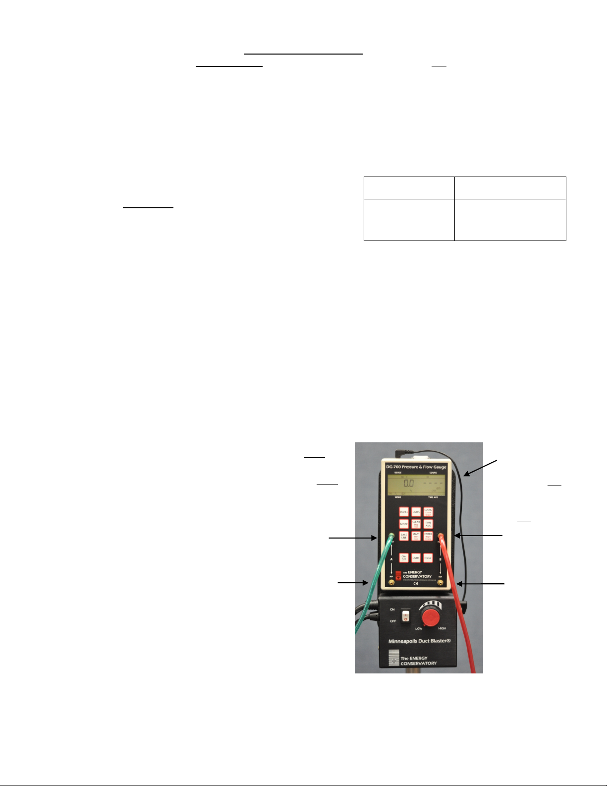
b) Connect tubing to the DG-700 as shown in
the illustration to the right.
** Your DG-700 gauge is compatible with Cruise Control if the CONFIG, CLEAR, START and ENTER keys have additional red
lettering below the main black script. Cruise Control also requires a Duct Blaster speed controller with a 3.5 mm communication jack
installed on the side of the controller box, and a fan control cable.
Connect the Red
tubing to the
Chan B Input tap.
The other end of
the Red tubing
should be
connected to the
brass tap in the
middle of the DB
fan housing.
Connect Chan A Ref
tap to inside of
building (if gauge is
located in the
building, leave this
tap open). Be sure
window is open.
Connect Chan B Ref
tap to space where
the fan is installed (if
fan and gauge are in
the same space,
leave this tap open).
Connect the Green (or
Clear) tubing to the
Chan A Input tap. The
other end of the Green
tubing should be
connected to the duct
system (by either
inserting into a sealed
register, or connecting
to the end of the
installed static
pressure probe).
Optional fan
control cable
(for Cruise Control).


