TECALEMIT TankQuick eco Operational manual
Translation of the original operating manual
TankQuick eco
Item-No.: 013896200, 013896210

2 44 1657 101-H TankQuick eco
TankQuick ecoTankQuick eco
TankQuick eco
Copyright
The operating manual is always to be read before commissioning the equipment.
The operating manual is always to be read before commissioning the equipment. The operating manual is always to be read before commissioning the equipment.
The operating manual is always to be read before commissioning the equipment.
No
No No
No warranty claim will be granted for faults and damage to the equipment arising
warranty claim will be granted for faults and damage to the equipment arising warranty claim will be granted for faults and damage to the equipment arising
warranty claim will be granted for faults and damage to the equipment arising
from insufficient knowledge of the operating manual.
from insufficient knowledge of the operating manual.from insufficient knowledge of the operating manual.
from insufficient knowledge of the operating manual.
© HORN GmbH & Co. KG. All rights reser ed.
Text, graphics and layout copyright protected. Reproduction and copying, including in
part, only permitted with written permission. Technical changes reser ed.
Service Hotline 49 1805 900 301
Reparatur Service 49 1805 900 302
(0,14 €/Min: on the German landline network, Mobile telephone max. 0,42 €/Min.)
service@tecalemit.de
Document-No.: 44 1657 101-H
Translation of: 44 1657 001-L
As of: February 12, 2020

44 1642 101-H TankQuick eco
TankQuick ecoTankQuick eco
TankQuick eco 3
Table of content
1
11
1 Safety instructions
Safety instructionsSafety instructions
Safety instructions
................................
................................................................
................................................................
................................................................
................................................................
................................................................
..................................
....
..
4
44
4
2
22
2 Technical description
Technical descriptionTechnical description
Technical description
................................
................................................................
................................................................
................................................................
..............................................................
............................................................
..............................
6
66
6
2.1 Product description / Appropriate use ............................................................. 6
2.2 Product ersions ...................................................................................................... 6
2.3 Equipment .................................................................................................................. 6
2.4 Technical data ........................................................................................................... 7
2.5 Accessories ................................................................................................................ 7
2.6 Outline drawing ........................................................................................................ 8
2.7 Functional diagram ................................................................................................. 8
3
33
3 Inst
InstInst
Installation
allationallation
allation
................................
................................................................
................................................................
................................................................
................................................................
................................................................
.................................................
..................................
.................
9
99
9
3.1 Place of installation ................................................................................................ 9
3.2 Change of location ................................................................................................... 9
3.3 Compressed Air Supply .......................................................................................... 9
4
44
4 Commissioning
CommissioningCommissioning
Commissioning................................
................................................................
................................................................
................................................................
................................................................
................................................................
..........................................
....................
..........
9
99
9
4.1 Specifying the Liquid .............................................................................................. 9
4.2 Operation with exchange containers ............................................................. 10
4.2.1 Emptying the deli ery systems .......................................................... 10
4.2.2 Changing the drum .................................................................................. 10
4.3 Adjusting the Operating Pressure ................................................................... 10
5
55
5 Operation
OperationOperation
Operation
................................
................................................................
................................................................
................................................................
................................................................
................................................................
................................................
................................
................
10
1010
10
5.1 Safety instructions ............................................................................................... 10
5.2 Remo ing Fuel ....................................................................................................... 11
5.2.1 Extracting fuel ia the filler pipe ....................................................... 11
5.2.2 Preparation of the hose set .................................................................. 11
5.2.3 Extracting fuel ia the fuel line ........................................................... 12
5.3 Refilling the Vehicle with Fuel ......................................................................... 13
5.3.1 Preparation oft he hose set .................................................................. 13
5.3.2 Refilling ....................................................................................................... 13
5.4 Breaks in works ..................................................................................................... 14
6
66
6 Ser icing and maintenance
Ser icing and maintenanceSer icing and maintenance
Ser icing and maintenance
................................
................................................................
................................................................
................................................................
................................................
................................
................
14
1414
14
6.1 Cleaning ................................................................................................................... 14
6.2 Container ................................................................................................................. 14
6.3 Dirt trap ................................................................................................................... 15
6.4 Pressure regulator ................................................................................................ 15
6.5 Deli ery system .................................................................................................... 15
6.6 Wheels ...................................................................................................................... 15
6.7 Type Plate and Warning Signs .......................................................................... 15
6.8 Troubleshooting .................................................................................................... 16
7
77
7 Spare parts
Spare partsSpare parts
Spare parts
................................
................................................................
................................................................
................................................................
................................................................
................................................................
.............................................
..........................
.............
17
1717
17
8
88
8 Disposal
DisposalDisposal
Disposal
................................
................................................................
................................................................
................................................................
................................................................
................................................................
...................................................
......................................
...................
18
1818
18
9
99
9 Declaration of c
Declaration of cDeclaration of c
Declaration of conformity
onformityonformity
onformity
................................
................................................................
................................................................
................................................................
..................................................
....................................
..................
19
1919
19

4 44 1657 101-H TankQuick eco
TankQuick ecoTankQuick eco
TankQuick eco
1Safety instructions
This de ice was manufactured taking into account the rele ant laws and directi es
for ensuring security as well as the protection of the en ironment and health. Despite
this, its use may result in hazards for persons and material assets. Hence, it is
essential that the instructions in this manual are complied with.
Warning notices and symbols
Warning notices and symbolsWarning notices and symbols
Warning notices and symbols
In this operating manual, the following symbols are used to point out especially
important information:
Specific details on the economic use of the device
Specific details on the economic use of the deviceSpecific details on the economic use of the device
Specific details on the economic use of the device.
Specific details and/or instructions for damage prevention
Specific details and/or instructions for damage preventionSpecific details and/or instructions for damage prevention
Specific details and/or instructions for damage prevention.
Details and/or instructions for preventing injury to persons or extensive material
Details and/or instructions for preventing injury to persons or extensive material Details and/or instructions for preventing injury to persons or extensive material
Details and/or instructions for preventing injury to persons or extensive material
damages
damagesdamages
damages
Intended use
Intended useIntended use
Intended use
Use the de ice only when it is in perfect working condition and only for its intended
purpose while obser ing all safety precautions and risks. In particular, all
malfunctions that could pose a safety hazard are to be corrected immediately.
The de ice and its components are intended for use exclusi ely with the liquids listed
and only for the purpose described. Any other use or additional manner of usage is
not intended.
Organizational measures
Organizational measuresOrganizational measures
Organizational measures
This operating manual is to be kept within easy reach at the place of operation. The
nameplate and the warning labels on the de ice must be obser ed and kept
completely legible at all times.
Qualified personnel
Qualified personnelQualified personnel
Qualified personnel
The personnel for installation, commissioning, operation, and maintenance of the
de ice must possess the rele ant and adequate qualifications for these tasks. The
operator must ensure that the contents of this manual are fully understood and
implemented by the personnel.
Maintenance and repairs
Maintenance and repairsMaintenance and repairs
Maintenance and repairs
Do not make any changes, extensions and/or modifications to the de ice without the
manufacturer's permission. Replacement parts must conform to the technical
specifications defined by the manufacturer. For original parts, this conformity is
always guaranteed.
Hazardous substances
Hazardous substancesHazardous substances
Hazardous substances
In exceptional cases, the components of this de ice may contain hazardous
substances. In accordance with the requirements of the European REACH regulation,
we pro ide current information on this on our homepage, in the download section.
Obser e all safety regulations for the respecti e product when handling oils, greases,
fuels and other chemical substances!

44 1642 101-H TankQuick eco
TankQuick ecoTankQuick eco
TankQuick eco 5
Hydraulics
HydraulicsHydraulics
Hydraulics
Only personnel with special knowledge of and experience in hydraulics are allowed to
perform work of any type on hydraulic equipment. Depressurize the de ice before
performing any work on it. All pressure-bearing components are to be inspected
regularly for leaks and damage.
Pneumatics
PneumaticsPneumatics
Pneumatics
Only personnel with special knowledge of and experience in pneumatics are allowed
to perform work of any type on pneumatic equipment. Depressurize the de ice
before performing any work on it. All pressure-bearing components are to be
inspected regularly for leaks and damage.
Explosion protection
Explosion protectionExplosion protection
Explosion protection
The de ice has been constructed for use with potentially explosi e substances. The
design and production took place in accordance with pre ailing regulations, in
particular the ATEX directi e 2014/34/EU and technical regulations. The operator is
to obser e all regulations for the operation of such de ices, in particular the ATEX
guideline 1999/92/EC and the respecti e regulations applicable at the place of
operation.
Water protection
Water protectionWater protection
Water protection
The de ice has been constructed for use with water contaminants. It is to be operated
such that bodies of water cannot be polluted by it. All applicable regulations at the
place of operation are to be complied with!

6 44 1657 101-H TankQuick eco
TankQuick ecoTankQuick eco
TankQuick eco
2Technical description
2.1
2.12.1
2.1 Product description
Product descriptionProduct description
Product description
/
/ /
/ Ap
ApAp
App
pp
propriate use
ropriate useropriate use
ropriate use
The TankQuick eco is a de ice for transferring fuel out of ehicle tanks into the
de ice's own containers, and for returning it to the empty tank. It was specifically
designed to be used in ehicle workshops, at filling stations and similar sites. It can be
used for emptying the tanks of ehicles on which repairs are to be carried out, and
for emptying tanks that ha e been wrFongly filled.
This
ThisThis
This
device is approved for use with potentially explosive liquids and for opera
device is approved for use with potentially explosive liquids and for operadevice is approved for use with potentially explosive liquids and for opera
device is approved for use with potentially explosive liquids and for opera-
--
-
tion in potentially explosive atmospheres. The permissible type of use is speci
tion in potentially explosive atmospheres. The permissible type of use is specition in potentially explosive atmospheres. The permissible type of use is speci
tion in potentially explosive atmospheres. The permissible type of use is speci-
--
-
fied by the Ex mark in the declaration of conformity and on the type plate. The
fied by the Ex mark in the declaration of conformity and on the type plate. The fied by the Ex mark in the declaration of conformity and on the type plate. The
fied by the Ex mark in the declaration of conformity and on the type plate. The
device may be opera
device may be operadevice may be opera
device may be operated exclusively with the liquids listed below.
ted exclusively with the liquids listed below.ted exclusively with the liquids listed below.
ted exclusively with the liquids listed below.
The de ice accords with the requirements of the applicable regulations, and in
particular with ATEX (2014/34/EU). This is certified by the Declaration of Conformity
and by the CE mark.
In addition the TankQuick has been subject to a GS-testing. The compliance of quality
and safety standards in engineering, production and quality management has been
appro ed. A regularly inspection by the testing authority is carried out. For
erification the de ice is marked with the GS-label.
In operation, the pneumatic double-membrane pump sucks the fuel out of the tank,
through the suction hose and into the container. The fuel is kept in the container
while the work is carried out. After changing o er the deli ery hoses, fuel is
discharged again from the container. The gas displacement de ice ensures that the
gases displaced during filling do not escape to the open air.
The container deli ered with the equipment is appro ed for the transport of the
appro ed liquids and can be exchanged with no great effort.
2.2
2.22.2
2.2 Product versions
Product versionsProduct versions
Product versions
The TankQuick eco is a ailable in two ariants. They differ in the type of suction
hose.
013 896 200 - TankQuick eco Suction hose 15x9 mm
013 896 210 - TankQuick eco S Suction hose 12x8 mm
2.3
2.32.3
2.3 Equipment
EquipmentEquipment
Equipment
•Four-wheeled trolley with 2 lockable steering rolls
•120 litre exchangeable container with le el display
•Pump unit with deli ery pump, fuel filter, compressed air regulator and starting
al e
•Hose system with filler pipe adapter, emptying/refilling hose and gas
displacement hose
•Accessories (optional): Adapter set for extraction ia the fuel hose

44 1642 101-H TankQuick eco
TankQuick ecoTankQuick eco
TankQuick eco 7
2.4
2.42.4
2.4 Technical data
Technical dataTechnical data
Technical data
Dimensions
Height
approx.
1096 mm
Width
approx.
483 mm
Depth
approx.
680 mm
Empty weight
With
container
approx.
35 kg
Noise emission
Free sound field,
accuracy class 2, EN ISO 11201
68,2dB +2,5dB
Container
Volume
120l
Useful olume
110l
Pump unit
Pumping capacity
approx.
7,5 l/min
Operating means
Compressed air, oil
-
free
filtered
Compressed air inlet
min 6
bar, max. 10 bar
Permissible ambient
temp.
Operation and breaks in work
5
°
…
40° C
Permissible media
temperature
5
°
…
40° C
Pumping media
Petrol, diesel,
E85 (ethanol fuel),
others on enquiry
2.5
2.52.5
2.5 Accessories
AccessoriesAccessories
Accessories
The following items can be used as accessories depending on the application:
Item-No.
Adapter set for extraction ia the fuel line 020 202 011
Exchange drum with le el display 013 896 300
Adapter for Mercedes C-Class 027 028 021

8 44 1657 101-H TankQuick eco
TankQuick ecoTankQuick eco
TankQuick eco
2.6
2.62.6
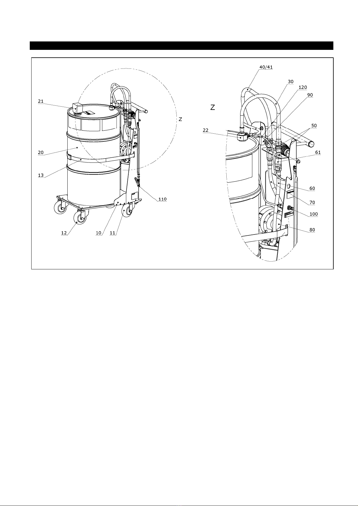
2.6 Outline drawing
Outline drawingOutline drawing
Outline drawing
Figure 1
2.7
2.72.7
2.7
Functional diagram
Functional diagramFunctional diagram
Functional diagram
Figure 2
44 1642 101-H TankQuick eco
TankQuick ecoTankQuick eco
TankQuick eco 9
3Installation
3.1
3.13.1
3.1 Place of installation
Place of installationPlace of installation
Place of installation
The TankQuick may only be used at sites such as petrol stations or workshops that
ha e been properly set-up for such work. The place of installation must be chosen in
such a way as neither to present danger to persons nor to pollute the en ironment.
The following points must be obser ed:
•The de ice must be used in such a way that any spilt fuel is trapped, is noticed,
and can be collected. It must therefore only be used and stored on a liquid-tight
floor. Spilt drops must be collected immediately.
•In accordance with TRBS 3151, the area with a radius of approx. 0.2 m around the
equipment is to be classified as Ex-zone 2. The de ice must therefore only be used
in the open air or in well- entilated rooms. The necessary explosi e hazard
protection measures must be taken.
In particular smoking, naked flames and working with tools that generate sparks
In particular smoking, naked flames and working with tools that generate sparks In particular smoking, naked flames and working with tools that generate sparks
In particular smoking, naked flames and working with tools that generate sparks
are forbidden in the vicinity of the device.
are forbidden in the vicinity of the device.are forbidden in the vicinity of the device.
are forbidden in the vicinity of the device.
•When not in use it must only be stored in rooms where people do not stay. Ensure
good entilation and that the temperature of the de ice will not rise.
•In order to disperse any static electric charge, the unit must not be placed on
insulating surfaces.
•The place of installation must offer sufficient protection against unauthorised use.
•It must be kept where it is protected from damage by third parties, e.g. not close
to the path of ehicles or working areas.
•The equipment is to be installed such that it is protected against influences of the
weather and also protected against heating up (e.g. direct sunlight).
3.2
3.23.2
3.2 Change of location
Change of locationChange of location
Change of location
When mo ing the TankQuick, it may be pushed / pulled exclusi ely by the handle of
the trolley. When parking it must always be ensured that the wheel locks are applied
securely.
3.3
3.33.3
3.3 Compressed Air
Compressed Air Compressed Air
Compressed Air Supply
SupplySupply
Supply
Fault
FaultFault
Fault-
--
-free operation involving relatively little servicing is only ensured if the
free operation involving relatively little servicing is only ensured if the free operation involving relatively little servicing is only ensured if the
free operation involving relatively little servicing is only ensured if the
supply of compressed air is free from dirt, water condensation and oil.
supply of compressed air is free from dirt, water condensation and oil.supply of compressed air is free from dirt, water condensation and oil.
supply of compressed air is free from dirt, water condensation and oil.
The use of a compressed air filter with an automatic condensate drain by the user is
to be greatly recommended.
An input pressure of at least 6 bar is necessary in order to reach the max. deli ery
flow rate.
4Commissioning
4.1
4.14.1
4.1 Specifying the Liquid
Specifying the LiquidSpecifying the Liquid
Specifying the Liquid
Liquid residues will be found e en when the container has been emptied. In order to
ensure that there is no mixing of sorts, the medium for a de ice must be specified
during commissioning (diesel, petrol or E85).
The operator is responsible for properly labeling the receptacles containing
The operator is responsible for properly labeling the receptacles containing The operator is responsible for properly labeling the receptacles containing
The operator is responsible for properly labeling the receptacles containing
hazardous materials.
hazardous materials.hazardous materials.
hazardous materials.

10 44 1657 101-H TankQuick eco
TankQuick ecoTankQuick eco
TankQuick eco
The hazardous material labels included in the scope of deli ery can be used for this
purpose.
4.2
4.24.2
4.2 Operation with exchange containers
Operation with exchange containersOperation with exchange containers
Operation with exchange containers
The container supplied with the unit is an open head drum, authorized for dangerous
goods transport of the appro ed medium (UN appro al no.
UN1A1/X300/2010/DBAM1166-GDH). It can, for example, be changed for single
ariety use with different mediums. Only replacement drums with a filling le el
indicator, a ailable as an accessory, may be used.
Emptying the delivery systems
Emptying the delivery systemsEmptying the delivery systems
Emptying the delivery systems
A small quantity of
A small quantity of A small quantity of
A small quantity of fuel remains in the delivery system after operation.
fuel remains in the delivery system after operation.fuel remains in the delivery system after operation.
fuel remains in the delivery system after operation.
In order to empty the system as completely as possible before exchanging the drum,
the extraction procedure should be carried out for approx. 15 sec with the suction
hose raised.
Changing the drum
Changing the drumChanging the drum
Changing the drum
In order to change the drum, dismount the drum connection, loosen the safety belt
and lift the drum off the trolley.
Place the new drum on the trolley, press it against the support plate and secure it
with the belt. Now mount the drum connection with fuel hose, gas displacement hose
and potential equalisation cable.
Check that the drum is secured after changing the drum and regularly during use!
Check that the drum is secured after changing the drum and regularly during use!Check that the drum is secured after changing the drum and regularly during use!
Check that the drum is secured after changing the drum and regularly during use!
4.3
4.34.3
4.3 Adjusting the Operating Pressure
Adjusting the Operating PressureAdjusting the Operating Pressure
Adjusting the Operating Pressure
The internal operating pressure is limited ia the de ice’s own pressure regulator. It
is preset in the factory to the max. permissible output pressure of 6 bar and fixed.
The max. pumping capacity of the de ice is reached at this pressure. A higher output
pressure is not possible.
Howe er, the operating pressure can be reduced if necessary with the pressure
regulator of the air supply system. For proper operation the input pressure may not
fall below 2 bar.
5Operation
5.1
5.15.1
5.1
Safety instructions
Safety instructionsSafety instructions
Safety instructions
The de ice may only be operated by trained personnel and under constant
super ision. The following points must be obser ed:
•Wear protecti e glo es when handling the TankQuick
•Inflammable fuels must only be put into containers that are suitable for this
purpose.
•The engine and the external heating of the ehicle whose fuel is to be remo ed or
returned must be switched off during operation.
•Suitable fire-fighting equipment must be to hand during operation (e.g. fire
extinguishers)
•The wheels' contact with the ground ensures that static buildup is discharged.
Hence, clean the wheels before operation if necessary.
•
Emergency stop In the e ent of a malfunction or an emergency, operation can be
stopped immediately by releasing the start button.
44 1642 101-H TankQuick eco
TankQuick ecoTankQuick eco
TankQuick eco 11
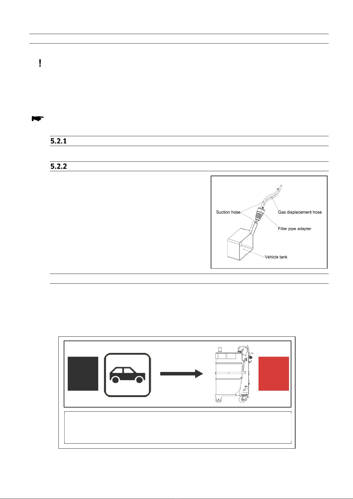
Hose to the ehide Hose to the container
BLACK RED
Left Right
5.2
5.25.2
5.2 R
RR
Removing Fuel
emoving Fuelemoving Fuel
emoving Fuel
Check the filling le el in the container before starting the extraction procedure.
Avoid overfilling the container
Avoid overfilling the containerAvoid overfilling the container
Avoid overfilling the container.
..
.
If o erfilling should ne ertheless occur, the excess pumping medium is fed back by
the gas displacement hose to the ehicle tank and o erfilling can be quickly
recognised in the transparent gas displacement hose. The extraction procedure must
then be stopped immediately.
Liquid can escape out of the level display if overfilling persists. This collects on
Liquid can escape out of the level display if overfilling persists. This collects on Liquid can escape out of the level display if overfilling persists. This collects on
Liquid can escape out of the level display if overfilling persists. This collects on
the drum lid and can be disposed of afterwards. The level display is to be cleaned
the drum lid and can be disposed of afterwards. The level display is to be cleaned the drum lid and can be disposed of afterwards. The level display is to be cleaned
the drum lid and can be disposed of afterwards. The level display is to be cleaned
and its functio
and its functioand its functio
and its functional capability checked.
nal capability checked.nal capability checked.
nal capability checked.
Extracting fuel via the filler pipe
Extracting fuel via the filler pipeExtracting fuel via the filler pipe
Extracting fuel via the filler pipe
As a rule the tank contents are extracted ia the ehicle filler pipe.
Prepa
PrepaPrepa
Preparation of t
ration of tration of t
ration of the hose set
he hose sethe hose set
he hose set
The suction hose set can be used as in the
deli ery condition with the suction hose fed
through the extraction adapter; see figure 3.
5.2.2.1
5.2.2.15.2.2.1
5.2.2.1
Extraction Procedure
Extraction ProcedureExtraction Procedure
Extraction Procedure
1. Mo e the TankQuick to the ehicle from which the fuel is to be extracted and
apply the parking brakes.
2. Attach the fastening clip of the potential equalisation cable to the ehicle.
3. Connect the deli ery hoses for the ‘extraction’ operating mode – pay attention to
the colour coding of the hoses:
Figure
3
Figure
4

12 44 1657 101-H TankQuick eco
TankQuick ecoTankQuick eco
TankQuick eco
4. Feed the suction/refilling hose into the ehicle tank and mount the filler pipe
adapter in the filler pipe.
During operation the filler pipe adapter must extend into the filler pipe and be
During operation the filler pipe adapter must extend into the filler pipe and be During operation the filler pipe adapter must extend into the filler pipe and be
During operation the filler pipe adapter must extend into the filler pipe and be
fixed securely!
fixed securely!fixed securely!
fixed securely!
5. Connect the compressed air.
6. Press the start button – the contents of the fuel tank are extracted.
The extraction procedure can be controlled ia the pumping noise of the pump. It
is possible that the pump may draw in air, e en though the ehicle tank has not
yet been fully emptied. In this case, the suction hose must either be pushed
further into the tank or pulled further out of the tank through the gripper piece in
the filler pipe. This should be done slowly and in short steps, since the suction
hose must first be refilled with liquid. Only then it is possible to discern the
pumping status of the pump.
The tank level must be monitored during the extraction procedure in order to
The tank level must be monitored during the extraction procedure in order to The tank level must be monitored during the extraction procedure in order to
The tank level must be monitored during the extraction procedure in order to
avoid overfilling.
avoid overfilling.avoid overfilling.
avoid overfilling.
7. After the extraction procedure is finished, allow the pump to run on briefly in
order to empty the hoses, then disconnect the de ice from the compressed air
supply.
Extracting fuel via the fuel line
Extracting fuel via the fuel lineExtracting fuel via the fuel line
Extracting fuel via the fuel line
Extraction takes place ia a suction hose connected to the ehicle’s fuel line. The
adapter set, which is a ailable as an accessory, is required for this.
Extraction via the fuel line may take place only with the permission of the
Extraction via the fuel line may take place only with the permission of the Extraction via the fuel line may take place only with the permission of the
Extraction via the fuel line may take place only with the permission of the
respective vehicle manufacturer!
respective vehicle manufacturer!respective vehicle manufacturer!
respective vehicle manufacturer!
5.2.3.1
5.2.3.15.2.3.1
5.2.3.1 Preparation of
Preparation ofPreparation of
Preparation of
the hose set
the hose setthe hose set
the hose set
The suction hose set must be mounted with the
adapter set according to figure 5. The assembly
instructions for the adapter set are to be
followed.
1. Pull the suction hose out of the filler pipe
adapter.
2. Fit the sealing plug into the free hole in the
filler pipe adapter.
3. Screw the hose adapter into the thread of the
ball point.
5.2.3.2
5.2.3.25.2.3.2
5.2.3.2
Extraction Procedure
Extraction ProcedureExtraction Procedure
Extraction Procedure
1. Mo e the TankQuick to the ehicle from which the fuel is to be extracted and
apply the parking brakes.
2. Attach the fastening clip of the potential equalisation cable to the ehicle.
3. Connect the deli ery hoses for the ‘extraction’ operating mode; see fig. 4.
4. Mount the filler pipe adapter with the gas displacement line in the filler pipe.
During operation the filler pipe adapter must extend into the filler pipe and be
During operation the filler pipe adapter must extend into the filler pipe and be During operation the filler pipe adapter must extend into the filler pipe and be
During operation the filler pipe adapter must extend into the filler pipe and be
fixed securely!
fixed securely!fixed securely!
fixed securely!
Figure
5

44 1642 101-H TankQuick eco
TankQuick ecoTankQuick eco
TankQuick eco 13
Hose to the container Hose to the ehicle
RED BLACK
Left Right
5. Feed the hose adapter with the suction hose into the fuel line.
6. Connect the compressed air.
7. Press the start button – the contents of the fuel tank are extracted.
The extraction procedure can be controlled ia the pumping noise of the pump.
During operation the filler pipe adapter must
During operation the filler pipe adapter mustDuring operation the filler pipe adapter must
During operation the filler pipe adapter must
extend into the filler pipe and be
extend into the filler pipe and be extend into the filler pipe and be
extend into the filler pipe and be
fixed securely!
fixed securely!fixed securely!
fixed securely!
8. If only air is still being sucked in by the pump, the extraction procedure can be
terminated. Allow the pump to run on briefly in order to empty the hoses, then
disconnect the de ice from the compressed air supply.
9.
5.3
5.35.3
5.3 Refilling the Vehicle with Fuel
Refilling the Vehicle with FuelRefilling the Vehicle with Fuel
Refilling the Vehicle with Fuel
Refilling the ehicle tank with fuel from the container may take place exclusi ely ia
the tank filler pipe.
Refilling the tank via the fuel line is not permitted!
Refilling the tank via the fuel line is not permitted!Refilling the tank via the fuel line is not permitted!
Refilling the tank via the fuel line is not permitted!
In order to avoid over
In order to avoid overIn order to avoid over
In order to avoid over-
--
-filling, only the
filling, only the filling, only the
filling, only the fuel that was removed from any particular
fuel that was removed from any particular fuel that was removed from any particular
fuel that was removed from any particular
vehicle should be returned to that vehicle.
vehicle should be returned to that vehicle.vehicle should be returned to that vehicle.
vehicle should be returned to that vehicle.
Preparation oft he hose set
Preparation oft he hose setPreparation oft he hose set
Preparation oft he hose set
The hose set is to be installed ia the filler pipe as for extraction (see chapter 5.2.1).
Refilling
RefillingRefilling
Refilling
1. Bring the TankQuick to the ehicle that is to be refuelled, and lock the wheels.
2. Attach the fastening clip of the potential equalisation cable to the ehicle.
3. Connect the deli ery hoses for the ‘refilling’ operating mode – pay attention to the
colour coding of the hoses:
Figure
6

14 44 1657 101-H TankQuick eco
TankQuick ecoTankQuick eco
TankQuick eco
4. Feed approx. 20 cm of the suction/refilling hose into the ehicle tank and mount
the filler pipe adapter in the filler pipe.
During operation the
During operation the During operation the
During operation the filler pipe adapter must extend into the filler pipe and be
filler pipe adapter must extend into the filler pipe and be filler pipe adapter must extend into the filler pipe and be
filler pipe adapter must extend into the filler pipe and be
fixed
fixedfixed
fixed
securely
securelysecurely
securely
5. Make the compressed air connection
6. Press the start button – the container contents are refilled into the tank.
7. To end the refilling procedure, release the start button and disconnect the de ice
from the compressed air supply.
5.4
5.45.4
5.4 Breaks in works
Breaks in worksBreaks in works
Breaks in works
The TankQuick is to be placed in special rooms during work breaks; see chapter 3.
The container on the device may be used exclusively for fuels in this particular
The container on the device may be used exclusively for fuels in this particular The container on the device may be used exclusively for fuels in this particular
The container on the device may be used exclusively for fuels in this particular
work step and must accordingly be emptied again after max. 1 day.
work step and must accordingly be emptied again after max. 1 day.work step and must accordingly be emptied again after max. 1 day.
work step and must accordingly be emptied again after max. 1 day.
If it is to be used for the storage of the extracted fuels, then the container must be
remo ed from the de ice and placed in a suitable storeroom that complies with the
regulations. The regulations applying to storage must be followed.
In order to ensure that the de ice works perfectly at all times, it should be emptied
before breaks in work if at all possible. To do this, carry out the emptying procedure
as described in the chapter “Refilling the Vehicle with Fuel” until only air exits from
the dispensing hose.
The ambient temperature specified in the chapter
The ambient temperature specified in the chapter The ambient temperature specified in the chapter
The ambient temperature specified in the chapter “Technical data” must also be
“Technical data” must also be “Technical data” must also be
“Technical data” must also be
maintained during breaks in work.
maintained during breaks in work.maintained during breaks in work.
maintained during breaks in work.
6Servicing and maintenance
6.1
6.16.1
6.1 Cleaning
CleaningCleaning
Cleaning
Clean the equipment only from the outside with cold or lukewarm water. Do not use
aggressi e detergents or soap. If a water hose is used, do not direct the water jet onto
the components at full pressure. Do not use steam-jet or high-pressure cleaners.
6.2
6.26.2
6.2 Container
ContainerContainer
Container
The container may only be filled with flammable liquids when in perfect condition. It
must be regularly checked for damages and corrosion.
A damaged container, or one which is not in perfect condition, may not be continued
to be used under any circumstances!

44 1642 101-H TankQuick eco
TankQuick ecoTankQuick eco
TankQuick eco 15
6.3
6.36.3
6.3 Dirt trap
Dirt trapDirt trap
Dirt trap
The dirt traps in the compressed air and deli ery system are to be cleaned at regular
inter als, examined for wear and renewed if necessary.
•Dirt trap on the suction side of the pump:
Undo the plug screw of the dirt trap and pull the sie e insert out in a downward
direction.
•Dirt trap in the compressed air supply:
Unscrew the pin of the compressed air connection from the threaded connection
of the pressure regulator. Unscrew the dirt trap from the connecting nozzle of the
pressure regulator using a suitable tool (e.g. flat-blade screwdri er). Seal the joint
when reassembling.
6.4
6.46.4
6.4 Pressure regulator
Pressure regulatorPressure regulator
Pressure regulator
Proper function of the air pressure regulator must be checked at regular inter als.
6.5
6.56.5
6.5 Delivery system
Delivery systemDelivery system
Delivery system
The deli ery system and in particular the deli ery hoses are to be examined regularly
for damage, check the couplings for leaks.
The metal sheathing of the deli ery hoses ensures the dissipation of static electric
charges.
Hoses without sufficient conductivity may not be used.
Hoses without sufficient conductivity may not be used.Hoses without sufficient conductivity may not be used.
Hoses without sufficient conductivity may not be used.
The connection of the wire mesh to the integrating parts must therefore be checked
regularly; the continuity must be measured if necessary.
6.6
6.66.6
6.6 Wheels
WheelsWheels
Wheels
The wheels of the TankQuick pro ide for potential equalisation to earth. They are also
to be cleaned and inspected for damage regularly.
The TankQuick is not to be operated if conductive contact with the ground cannot
The TankQuick is not to be operated if conductive contact with the ground cannot The TankQuick is not to be operated if conductive contact with the ground cannot
The TankQuick is not to be operated if conductive contact with the ground cannot
beensured.
beensured.beensured.
beensured.
Therefore, exclusively spare wheels
Therefore, exclusively spare wheels Therefore, exclusively spare wheels
Therefore, exclusively spare wheels procured from the manufacturer may be
procured from the manufacturer may be procured from the manufacturer may be
procured from the manufacturer may be
mounted!
mounted!mounted!
mounted!
6.7
6.76.7
6.7 Type Plate and Warning Signs
Type Plate and Warning SignsType Plate and Warning Signs
Type Plate and Warning Signs
The warning signs attached to the device and the type plate must be well legible.
The warning signs attached to the device and the type plate must be well legible. The warning signs attached to the device and the type plate must be well legible.
The warning signs attached to the device and the type plate must be well legible.
Dirty signs must be cleaned, and replaced if necessary.
Dirty signs must be cleaned, and replaced if necessary.Dirty signs must be cleaned, and replaced if necessary.
Dirty signs must be cleaned, and replaced if necessary.

16 44 1657 101-H TankQuick eco
TankQuick ecoTankQuick eco
TankQuick eco
6.8
6.86.8
6.8 Troubleshooting
TroubleshootingTroubleshooting
Troubleshooting
Fault Possible cause Action
Pump does not start
Compressed air not connected
Connect the compressed air
supply and check the input
pressure
Start button not pressed
The start button must be kept
pressed during operation
Operating pressure too low
–
input pressure to low
The input pressure is of < 2 bar
Check the adjustment of the
pressure regulator of the air
supply and switch to a higher
input pressure
Low or no pumping
capacity
Wrong pumping direction
Connect the
deli ery hoses
according to the desired mode
of operation (chapter 5)
Difficult operating conditions
The pumping capacity is limited
when extracting through
winding filler pipes and with
small suction hose cross-
sections.
Operating pressure too low
–
input pressure of the compressed
air supply too low
Check the input pressure of the
compressed air supply, the
input pressure must exceed the
desired operating pressure.
Leak in the compressed air
system
Examine the compressed air
system for leaks, clean and
replace damaged parts if
necessary
Dirt trap in the compressed air
system is dirty
Remo e the dirt trap from the
pressure regulator and clean it
(chapter 6.3)
Silencer on the pump is dirty
Clean the silencer
Dirt trap in the deli ery
system is
dirty
Remo e the sie e from the dirt
trap and clean it (chapter 6.3)
Suction line kinked or damaged
Check the fuel suction/refilling
line for possible damage
Ser ice life of the wearing parts
of the pump exceeded
Return the pump for
o erhaul
44 1642 101-H TankQuick eco
TankQuick ecoTankQuick eco
TankQuick eco 17
7Spare parts
Pos.
Designation Item no.
10 Chassis 516570001
11 Castor with brake – electrically conducti e 491102900
12 Castor – electrically conducti e 491103300
13 Safety belt 492000800
20 Barrel 120 Liter 816578001
21 Le el display with barrel adapter 816578005
22 Barrel adapter with suction tube 816578009
30 Barrel hose with quick coupling 816578004
40 Deli ery hose, quick coupling and tank adapter eco 816578003
41 Deli ery hose, quick coupling and tank adapter eco s 816578002
50 Plug for quick coupling 422322400
60 Fuel suction hose 816578010
61 Dirt trap 409001500
70 Fuel pressure hose 816578011
80 Feed pump 432202700
90 Start button 816578006
100 Compressed air connection with pressure regulator 816578007
110 Potential equalisation cable to the ehicle 813740012
120 Potential equalisation cable chassis to barrel 816578021

18 44 1657 101-H TankQuick eco
TankQuick ecoTankQuick eco
TankQuick eco
8Disposal
The de ice is to be emptied completely and the liquids properly disposed of in case it
is taken out of ser ice.
The equipment is to be disposed of properly when taken permanently out of ser ice:
- Return old metal for recycling.
- Return plastic parts for recycling.
- Return electronic waste for recycling.
The water legal regulations are to be followed.
The water legal regulations are to be followed.The water legal regulations are to be followed.
The water legal regulations are to be followed.
44 1642 101-H TankQuick eco
TankQuick ecoTankQuick eco
TankQuick eco 19
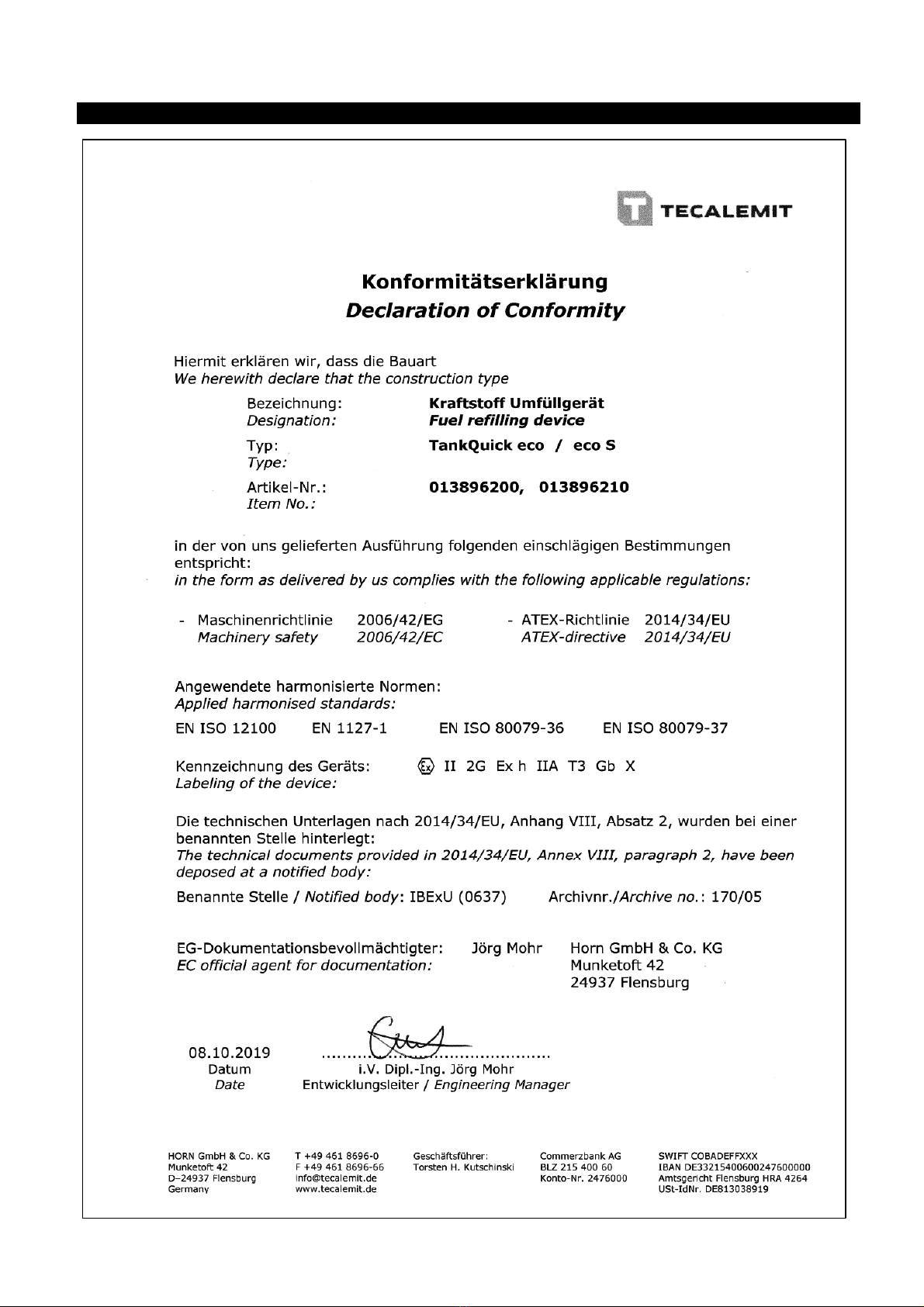
9Declaration of conformity

20 44 1657 101-H TankQuick eco
TankQuick ecoTankQuick eco
TankQuick eco
HORN GmbH & Co. KG
Mun etoft 42
24937 Flensburg
Germany
T +49 461-8696-0
F +49 461-8696-66
www.tecalemit.de
This manual suits for next models
3
Table of contents
Other TECALEMIT Service Equipment manuals

Popular Service Equipment manuals by other brands

Hofmann
Hofmann monty 3300 2speed 24/GP Operation manual

JBM
JBM 53873 instruction manual

AVL DITEST
AVL DITEST VAS 6910 Unpacking Instructions, Start-up, Brief instructions

Race Ramps
Race Ramps RR-STR instructions

Spin
Spin COUNTRY CLIMA Manual for use and maintenance

BGS technic
BGS technic 1674 instruction manual


