TECH ST-19 User manual

Principle of operation
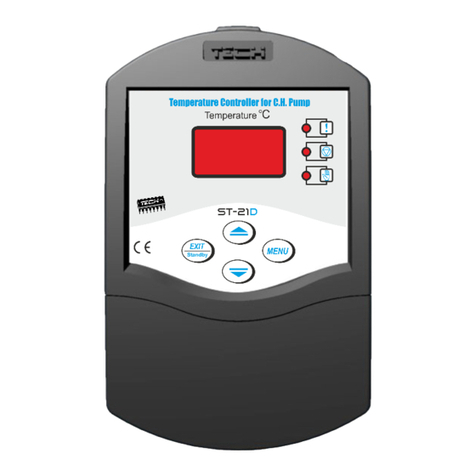
The ST-19 regulator is responsible for controlling the central heating pump. It is used
to start the pump when the temperature exceeds a given value and stop it when the
boiler has cooled down (as a result of damping). This is to prevent the pump from
runningunnecessarilyandsaveenergyconsumedbytheboiler(upto60%depending
on the amount of use), as well as extend the life of the pump, while increasing its
reliabilityandreducingrunningcosts.
Operation
The pump switch-on temperature is set with a potentiometer (between 25oC and
85oC). The pump is stopped when the actual temperature drops 2oC below the
setpoint value (set with the potentiometer). Thus, the pump is not switched on and off
incycles(reducingitslifespan)asaresultofsmallchangesofthetemperature.
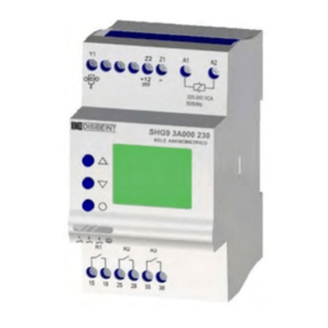
Apart from the potentiometer, the regulator is fitted with an ON/OFF switch
(POWER LED lit), manual pump start-up button (MANUAL MODE LED lit) and a
DUTY LED to indicate that the pump is running.
ANTI-STOP
The regulator is also intended for protecting the motor against blockage. The pump is
started every 10 days for 5 minutes. Additionally, the current time is stored within
EEPROMmemorytomakesurethetimeiscorrectevenafterapowerfailure.
TheregulatorisprotectedwithaWT1.6Atubefuse.
Installation
Allconnectionworksmustonlybecarriedoutbyqualifiedelectricians.
The sensor should be located at the boiler outlet with a band clip and separated from
externalconditionswithaninsulationtape.
The power supply line should be connected as follows: blue and brown – 230 V,
yellow-green(protective)shouldbeearthed
Thedistancebetweentheinstallationholesis123.6mm.
ATTENTION!
High voltage!
Make sure the regulator is disconnected from the mains before installation (pump
cableconnections,deviceinstallation,etc.)!
Donotdisassembletheregulatoranddonotinsertanyobjectsthroughtheinstallation
holes. The regulator must be protected against contamination and humidity. Any
damage to the housing may lead to an electric shock. The device needs to be
connectedtoagroundedcircuit.
!! !!
ST-19 ST-19
tech tech

....................... ....................... ....................... .......................
Salespersonstamp Dateofsale Salespersonstamp Dateofsale
1. Potentiometer 1. Potentiometer
2. Powerswitch 2. Powerswitch
3. PowerindicationLED 3. PowerindicationLED
4. PumpdutyindicationLED 4. PumpdutyindicationLED
5. Temperaturesensor 5. Temperaturesensor
6. Centralheatingpumpoutput 6. Centralheatingpumpoutput
7. Powersupply 7. Powersupply
8. 1Afuse
9. ManualmodeindicationLED
10.Manualmodebutton
8. 1Afuse
9. ManualmodeindicationLED
10.Manualmodebutton
O O
Ambienttemperature 0 C-40 C O O
Ambienttemperature 0 C-40 C
WARRANTY WARRANTY
Tech warrants to the Buyer that the device will be free of any defects for a period of
24monthsfromthedateofsale(upto30monthsfromthedateofproduction).Adefectivedevice
should be returned to the point of sale, accompanied by this Warranty Card with a confirmed
date of purchase. The faulty device will be replaced by the warrantor provided that the fault is
attributabletothemanufacturer.
The Warranty does not cover damage due to improper use or attributable to the user,
mechanicaldamageordamagecausedbyatmosphericdischarges,overvoltage,short-circuits. The Warranty does not cover damage due to improper use or attributable to the user,
mechanicaldamageordamagecausedbyatmosphericdischarges,overvoltage,short-circuits.
This Warranty Card is valid only with a receipt (invoice) containing the date of sale,
dateofdeliveryandsignatures.Itisrecommendedtoencloseabriefdescriptionofthefault.The
parcelshouldbeprovidedwithsender’sfulladdressandtelephonenumber.
This Warranty Card is valid only with a receipt (invoice) containing the date of sale,
dateofdeliveryandsignatures.Itisrecommendedtoencloseabriefdescriptionofthefault.The
parcelshouldbeprovidedwithsender’sfulladdressandtelephonenumber.
1 1
5 5
6 6
7 7
8 8
2 2
Temperatureadjustmentrange O O
25 C-85 C Temperatureadjustmentrange O O
25 C-85 C
O
Hysteresis 2 C O
Hysteresis 2 C
Powerconsumption 1W Powerconsumption 1W
Supplyvoltage 230V/50Hz+/-10% Supplyvoltage 230V/50Hz+/-10%
Sensorcablelength do1.5m Sensorcablelength do1.5m
Output 230V/50Hz Output 230V/50Hz
Max.outputloadcurrent 1A Max.outputloadcurrent 1A
O
Measurementerror +/-1 C O
Measurementerror +/-1 C
10 10
ST-19 ST-19
2-YEAR
WARRANTY
2-YEAR
WARRANTY
Temperature Regulator Temperature Regulator
Anti-Stop Anti-Stop
Other TECH Controllers manuals
