TECHFIT B380 User manual

1
MAGNETIC UPRIGHT BIKE
OWNER’S MANUAL
BENUTZERHANDBUCH
MANUALUL UTILIZATORULUI
IMPORTANT: Read all instructions carefully before using this product. Retain this
owner’s manual for future reference.
The specifications of this product may vary from this photo, subject to change without
notice.

2
EN. TABLE OF CONTENTS
SAFETY INSTRUCTIONS.......................................................................................................3
PARTS LIST ..............................................................................................................................4
HARDWARE PACKING LIST.................................................................................................5
TOOLS.......................................................................................................................................5
OVERVIEW DRAWING...........................................................................................................6
ASSEMBLY INSTRUCTIONS.................................................................................................7
OPERATING THE COMPUTER............................................................................................11
MAINTENANCE....................................................................................................................12
TROUBLESHOOTING...........................................................................................................13
WARM UPAND COOL DOWN ROUTINE..........................................................................14
D. INHAL TCVERZIECHNIS
SICHERHEITSHINWEISE.....................................................................................................18
LISTE DER BESTANDTEILE ...............................................................................................19
LISTE DER GESCHMIEDETEN DICHTUNGEN................................................................21
WERKZEUGE.........................................................................................................................21
GRAPHISCHE DARSTELLUN .............................................................................................22
MONTAGEANLEITUNG.......................................................................................................23
BETRIEB DES COMPUTERS ...............................................................................................27
INSTANDHALTUNG .............................................................................................................28
RO. CUPRINS
INSTRUCŢIUNI PRIVIND SIGURANŢA ............................................................................34
LISTA DE COMPONENTE....................................................................................................35
LISTA DE ARTICOLE DE FIERĂRIE DIN GARNITURĂ ..................................................37
UNELTE ..................................................................................................................................39
DESEN DE PREZENTARE....................................................................................................40
INSTRUCŢIUNI DE ASAMBLARE......................................................................................41
OPERAREA CALCULATORULUI........................................................................................44
ÎNTREȚINEREA.....................................................................................................................45
SOLUŢIONAREA PROBLEMELOR.....................................................................................46
RUTINA DE ÎNCĂLZIRE ŞI DE RELAXARE.....................................................................47

EN
3
SAFETY INSTRUCTIONS
Basic precautions should always be followed, including the following safety
instructions when using this equipment: Read all instructions before using this
equipment.
1. Read all the instructions in this manual and do warm up exercises before using
this equipment.
2. Before exercise, in order to avoid injuring the muscle, warm-up exercise of every
position of the body is necessary. Refer to Warm Up and Cool Down Routine
pages. After exercise, relaxation of the body is suggested for cool-down.
3. Please make sure all parts are not damaged and fixed well before use. This
equipment should be placed on a flat surface when using. Using a mat or other
covering material on the ground is recommended.
4. Please wear proper clothes and shoes when using this equipment; do not wear
clothes that might catch any part of the equipment; remember to tighten the
pedaling straps.
5. Do not attempt any maintenance or adjustments other than those described in
this manual. Should any problems arise, discontinue use and consult an
Authorized Service Representative.
6. Do not use the equipment outdoors.
7. This equipment is for household use only.
8. Only one person should be on the equipment while in use.
9. Keep children and pets away from the equipment while in use. This machine is
designed for adults only. The minimum free space required for safe operation is
not less than two meters.
10. If you feel any chest pains, nausea, dizziness, or short of breath, you should stop
exercising immediately and consult your physician before continuing.
WARNING: Before beginning any exercise program consult your
physician. This is especially important for the persons who are over 35 years
old or who have pre-existing health problems. Read all instructions before
using any fitness equipment.
CAUTION: Read all instructions carefully before operating this
product. Retain this Owner’s Manual for future reference.
11. The maximum weight capacity for this product is 120 kgs.

EN
4
PARTS LIST
No.
Description
Qty
No.
Description
Qty
001
Main Frame
1
030
Cap Nut M8
4
002
Front Stabilizer
1
031
Flywheel Ø230x40xØ32
1
003
Rear Stabilizer
1
032
Bearing Cup
2
004
Idle Wheel Bracket
1
033
Bearing 6000ZZ
2
005
Seat Post
1
034
Bearing Nut I 15/16"
1
006
Seat Sliding Tube
1
035
Bearing Nut II 7/8"
1
007
Handlebar Post
1
036
Washer Ø24xØ40x3.0
1
008
Handlebar
1
037
Washer Ø23xØ34.5x2.5
1
009
U Bracket
2
038
Hexagon Nut 7/8"
1
010
Washer Ø16xØ8x1.5
6
039
Belt Pulley with Crank Ø240J6
1
011
Eyebolt M8x85
1
040
Bolt M5X45
1
012
End Cap For Front Stabilizer
2
041
Big Curve Washer Ø5
1
013
End Cap For Rear Stabilizer
2
042
Bolt M5X10
4
014
Big Curve Washer Ø8
8
043
Handlebar Foam Grip
Ø24xØ30x550
2
015
Adjustable Leveler M8
1
044
Left Pedal YH-30X
1
016
Spring Ø6
2
045
Right Pedal YH-30X
1
017
Bolt M8x70
4
046
End Cap for Handlebar
2
018
Seat Sliding Tube End Cap (□
38)
2
047
Cover Cap
2
019
Bolt M8x15
4
048
Round Knob M16
1
020
Bolt M8x20
1
049
Hand Pulse Sensor with Wire
L=750mm
2
021
Eyebolt M6x36
2
050
Sensor with Wire L=750mm
1
022
Idle Wheel Ø10xØ35
1
051
Left Chain Cover
1
023
Screw ST2.9×12
2
052
Right Chain Cover
1
024
Screw ST4.2×20
6
053
Seat Post Bushing
1
025
Screw ST4.2×25
7
054
Tension Control Knob
1
026
Pan Head Phillips Self Drilling
Screw ST4.2x25
4
055
Tension Cable L=1150mm
1
027
Nylon Nut M8
6
056
Clamp Cover
1
028
Nut M6
2
057
Spacer (Ø12x20x1.5)
1
029
Hexagon Nut M10
2
058
Handlebar Post Cover
1
059
Seat Post Cover
1
064
Handlebar T-Knob (M8x55)
1
060
Belt PJ360 J6
1
065
Washer Ø12x Ø6x1.0
1
061
Seat Cushion DD-982AT
1
066
Bolt M6X10
1
062
Computer
1
067
Plug
1
063
Extension Sensor Wire
(L=1000mm)
EN
5
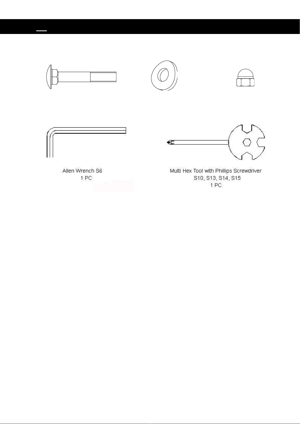
HARDWARE PACKING LIST
TOOLS
(17) Bolt M8x70
4 PCS
(14) Big Curve Washer Ø8
4 PCS
(30) Cap Nut M8
4 PCS
EN
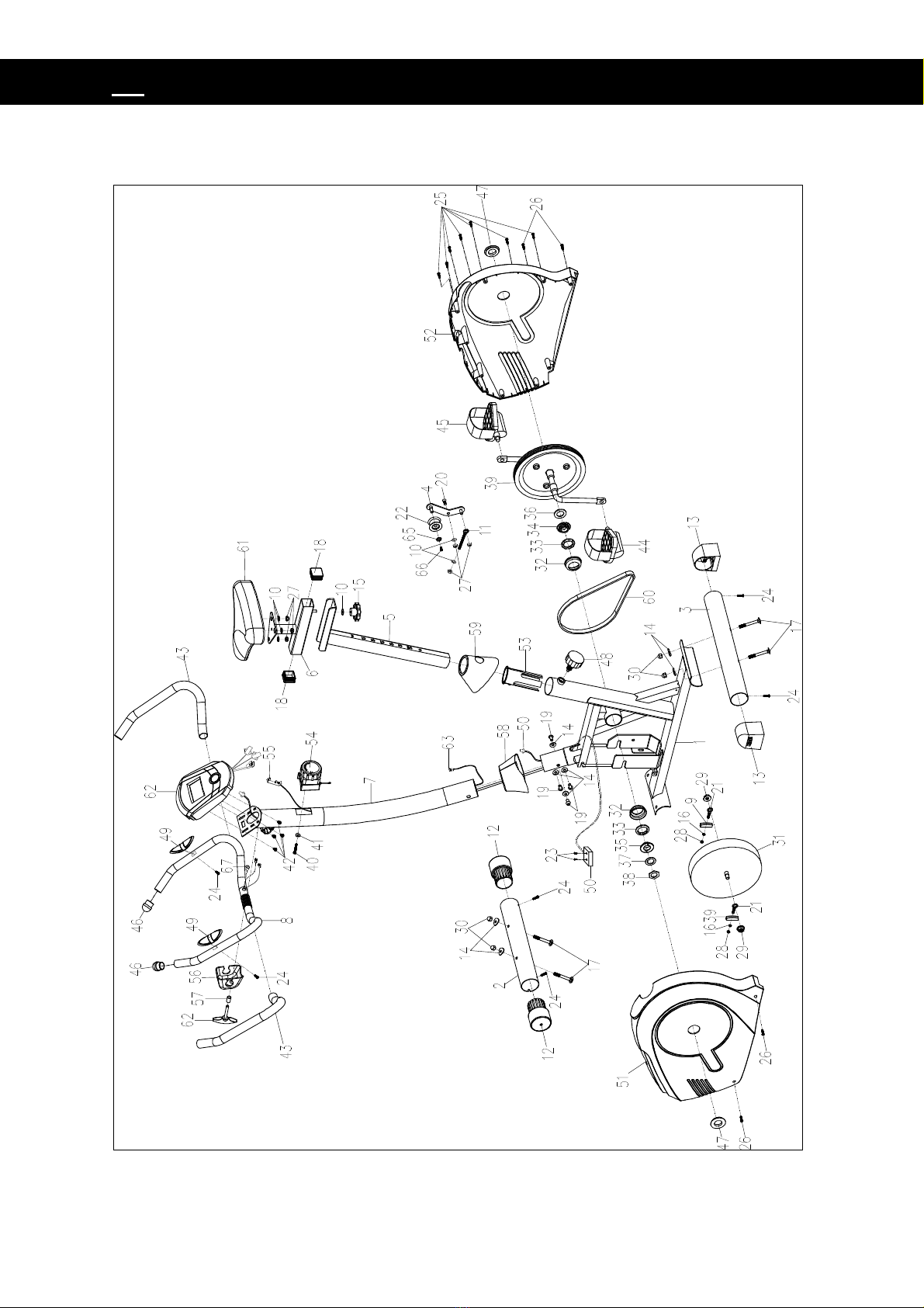
6
OVERVIEW DRAWING
EN
7
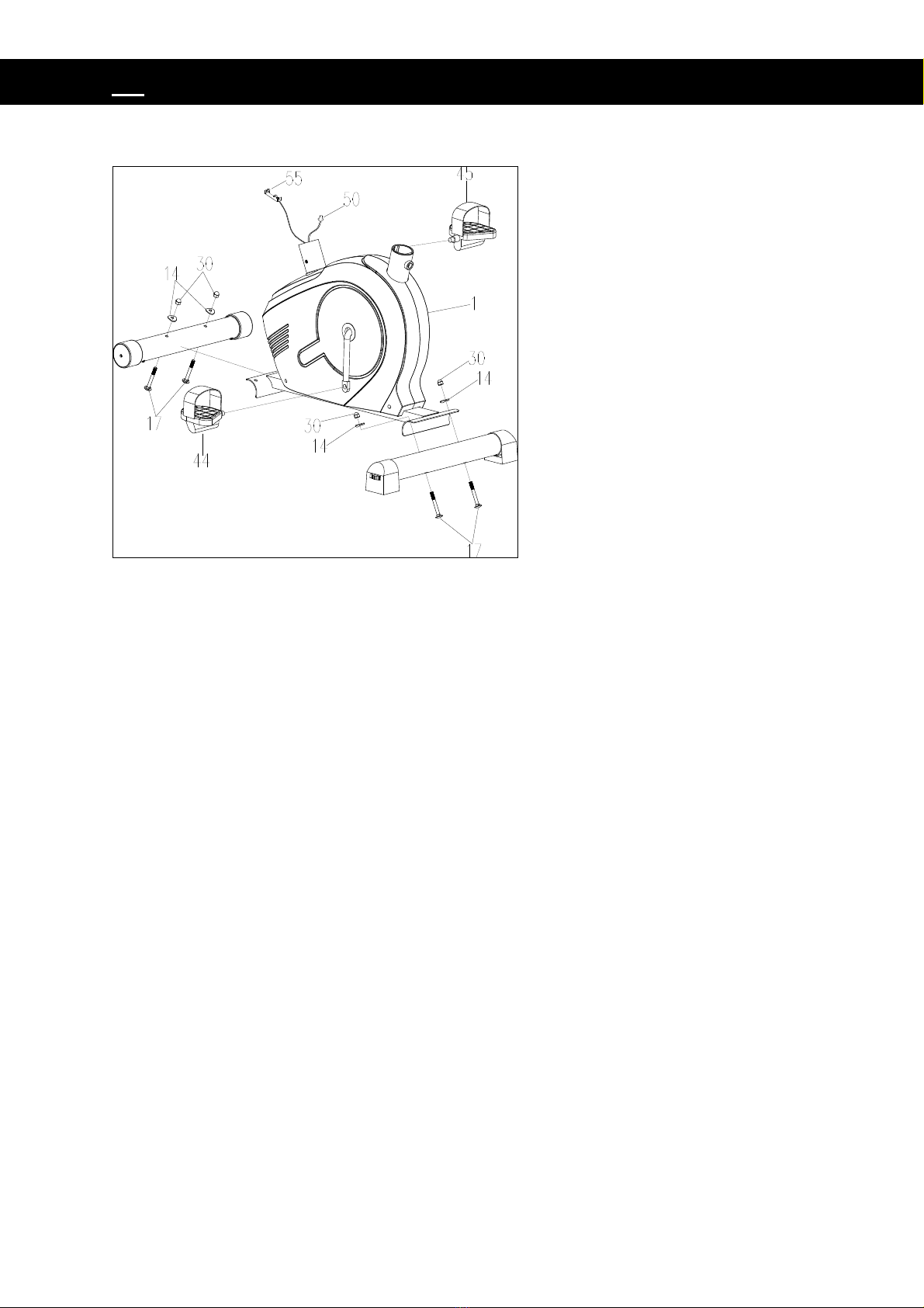
ASSEMBLY INSTRUCTIONS
1. Front and Rear Stabilizers Installation
Position the Front Stabilizer (2) in front of the Main Frame (1) and align bolt holes.
Attach the Front Stabilizer (2) onto the front curve of the Main Frame (1) with two M8x70
Bolts (17), two Ø8 Big Curve Washers (14), and two M8 Cap Nuts (30).
Position the Rear Stabilizer (3) behind the Main Frame (1) and align bolt holes.
Attach the Rear Stabilizer (3) onto the rear curve of the Main Frame (1) with two M8x70
Bolts (17), two Ø8 Big Curve Washers (14), and two M8 Cap Nuts (30).
2. Foot Pedals Installation
The Cranks, Foot Pedals, Pedal Shafts and Pedal Straps are marked “R” for
Right and “L” for Left.
Insert the pedal shaft of Left Foot Pedal (44) into threaded hole in the left Crank (39).
Turn the pedal shaft by hand in the counter-clockwise direction until snug.
Note: DO NOT turn the pedal shaft in the clockwise direction, doing so will strip
the threads.
Screwdriver provided Insert pedal shaft of Right Foot Pedal (45) into threaded hole in
right Crank (39). Turn the pedal shaft by hand in the clockwise direction until snug.

EN
8
3. Seat Post, Seat Post Cover, Seat Cushion, and Seat Sliding Tube
Installation
Slide the Seat Post Cover (59) onto the tube of the Main Frame (1). Insert the Seat
Post (5) into the Seat Post Bushing (53) on the tube of the Main Frame (1) and then
attach the Seat Post Knob (48) onto the tube of the Main Frame (1) by turning it in a
clockwise direction with Multi Hex Tool provided to lock the Seat Post (5) in the
suitable position.
Remove three M8 Nylon Nuts (27) and three Ø16xØ8x1.5 Washers (10) from
underside of the Seat Cushion (61). Remove nylon nuts and washers with the Multi
Hex Tool with Phillips Screwdriver provided. Guide bolts on underside of the Seat
Cushion (61) through holes on top of the Seat Sliding Tube (6), attach with three
removed M8 Nylon Nuts (27) and Ø16xØ8x1.5 Washers (10). Tighten nylon nuts and
washers with the Multi Hex Tool with Phillips Screwdriver provided.
Guide the Seat Sliding Tube Bolt on underside of the Seat Sliding Tube (6) through
hole on top of the Seat Post (5), attach with one Ø10xØ20x2 Washer (10) and Seat
Adjustment Knob (15).

EN
9
4. Handlebar Post, Handlebar Post Cover, and Tension Control Knob
Installation
Remove four M8x15 Bolts (19), four Ø20xØ8x2.0 Washers (14) from the Main Frame
(1). Remove bolts with the S6 Allen Wrench provided.
Slide the Handlebar Post Cover (58) up to the Handlebar Post (7).
Insert the Tension Cable (55) through into the bottom hole of Handlebar Post (7) and
pull it out from the square hole of Handlebar Post (7).
Connect the Sensor Wire (50) from the Main Frame (1) to the Extension Sensor Wire
(63) from the Handlebar Post (7).
Insert the Handlebar Post (7) onto the tube of the Main Frame (1) and secure with
four M8x15 Bolts (19), four Ø20xØ8x2.0 Washers (14) that were removed. Tighten
bolts with the S6 Allen Wrench provided.
Slide the Handlebar Post Cover (58) down to the Handlebar Post (7).
Remove the M5x45 Bolt (40) and Ø5 Big Washer (41) from the Tension Control Knob
(54). Remove bolt with the Multi Hex Tool with Phillips Screwdriver provided.

EN
10
Put the cable end of resistance cable of Tension Control Knob (54) into the spring
hook of Tension Cable (55) as shown in drawing A of figure 3. Pull the resistance
cable of Tension Control Knob (54) up and force it into the gap of metal bracket of
Tension Cable (55) as shown in drawing B of figure 3. Attach the Tension Control
Knob (54) onto the Handlebar Post (7) with the M5x45 Bolt (40) and Ø5 Big Washer
(41) that were removed. Tighten bolt with the Multi Hex Tool with Phillips Screwdriver
provided.
5. Handlebar Installation, Computer
Insert the Hand Pulse Sensor Wires (49)
into the hole on the Handlebar Post (7) and
then pull them out from the top end of the
Handlebar Post (7). Place the Handlebar (8)
through clamp on the Handlebar Post (7)
with hand pulse sensors facing the seat.
Hold the Handlebar (8) in desired position
and fasten Clamp Cover (56), Ø12x20x1.5
Spacer (57), and Handlebar T-Knob (62)
onto clamp. Tighten the Handlebar T-Knob
(62) after adjustment.
NOTE: Handlebar T-Knob should be
tightly secured before using.
6. Computer Installation
Remove four M5x10 Bolts (42) from the
Computer (62). Remove bolts with the Multi
Hex Tool with Phillips Screwdriver provided.
Connect the Hand Pulse Sensor Wires (49)
and Extension Sensor Wire (63) to the wires
that come from the Computer (62). Tuck
wires into the Handlebar Post (7). Attach the
Computer (62) onto the top end of the
Handlebar Post (7) with four M5x10 Bolts
(42) that were removed. Tighten bolts with
the Multi Hex Tool with Phillips Screwdriver
provided.

EN
11
OPERATING THE COMPUTER
SPECIFICATIONS:
TIME--------------------------------------------------0:00 - 99:59 MIN:SEC
SPEED-----------------------------------------------0.0 –999.9 KM/H OR ML/H
DISTANCE------------------------------------------0.00 –99.99 KM OR ML
CALORIES------------------------------------------0.0 –999.9 KCAL
TOTAL/ODOMETER------------------------------0.00 –99.99 KM OR ML
PULSE-----------------------------------------------40 - 200 BEATS/MIN
KEY FUNCTION:
MODE: To select the function you want. Hold the key for 4 seconds to have all
function values reset except the TOTAL.
SET: To input the target value.
RESET: To let the value reset.
OPERATION PROCEDURES:
AUTO ON/OFF The monitor will be automatically shut off if there is no signal coming
in for 4 minutes. The monitor will be auto-powered when start exercise or press the
key.
FUNCTION:
<1>.TIME(TMR) Auto-memorize the workout time while exercising.
<2>.SPEED(SPD) Display the current speed.
<3>.DISTANCE(DST) Accumulate the distances while exercising.
<4>.TOTAL/ODO Display the total distances while exercising. When the
signal input, it start the value up on the original data. The TOTAL/ODO can’t be
reset(by any key)except you replace battery once.
<5>.CALORIES(CAL) Auto-memorize calories amount consumed while
exercising.
<6>.PULSE(PUL) Display the user’s heart rate per minute while exercising.
Remark: You have to hold on reaction planks with both hands.
<7>.SCAN Automatically scan through each function
BATTERY:
If there is a possibility to see an improper display on the monitor, please replace the
batteries to have a good result. This monitor uses two “AA”or one“AAA” battery or
one“1.5V” button battery. You can replace the batteries at the same time.

EN
12
MAINTENANCE
Cleaning
The upright bike can be cleaned with a soft cloth and mild detergent. Do not use
abrasives or solvents on plastic parts. Please wipe your perspiration off the upright
bike after each use. Be careful not get excessive moisture on the computer display
panel as this might cause an electrical hazard or electronics to fail.
Please keep the upright bike, specially, the computer console, out of direct sunlight to
prevent screen damage.
Please inspect all assembly bolts and pedals on the machine for proper tightness
every week.
Storage
Store the upright bike in a clean and dry environment away from children.

EN
13
TROUBLESHOOTING
PROBLEM
SOLUTION
The upright bike wobbles when in use.
Turn the adjustable leveler on the rear
stabilizer as needed to level the upright
bike.
There is no display on the computer
console.
1. Remove the computer console and
verify the wires that come from the
computer console are properly
connected to the wires that come
from the handlebar post.
2. Check if the batteries are correctly
positioned and battery springs are in
proper contact with batteries.
3. The batteries in the computer
console may be dead. Change to
new batteries.
There is no heart rate reading or heart rate
reading or is erratic / inconsistent.
1. Make sure that the wire connections
for the hand pulse sensors are
secure.
2. To ensure the pulse readout is more
precise, please always hold on to the
handlebar grip sensors with two
hands instead of just with one hand
only when you try to test your heart
rate figures.
3. Gripping the hand pulse sensors too
tight. Try to maintain moderate
pressure while holding onto the hand
pulse sensors.
The upright bike makes a squeaking noise
when in use.
The bolts may be loose on the upright
bike, please inspect the bolts and tighten
the loose bolts.

EN
14
WARM UP AND COOL DOWN ROUTINE
A good exercise program consists of a warm-up, aerobic exercise, and a cool down.
Do the entire program at least two to three times a week, resting for a day between
workouts. After several months you can increase your workouts to four or five times
per week.
AEROBIC EXERCISE is any sustained activity that sends oxygen to your muscles via
your heart and lungs. Aerobic exercise improves the fitness of your lungs and heart.
Aerobic fitness is promoted by any activity that uses your large muscles eg: legs,
arms and buttocks. Your heart beats quickly and you breathe deeply. An aerobic
exercise should be part of your entire exercise routine.
The WARM-UP is an important part of any workout. It should begin every session to
prepare your body for more strenuous exercise by heating up and stretching your
muscles, increasing your circulation and pulse rate, and delivering more oxygen to
your muscles.
COOL DOWN at the end of your workout, repeat these exercises to reduce soreness
in tired muscles.
HEAD ROLLS
Rotate your head to the right for one count,
feeling the stretch up the left side of your neck,
then rotate your head back for one count,
stretching your chin to the ceiling and letting
your mouth open. Rotate your head to the left for
one count, then drop your head to your chest for
one count.
SHOULDER LIFTS
Lift your right shoulder toward your ear for one
count. Then lift your left shoulder up for one
count as you lower your right shoulder.

EN
15
SIDE STRETCHES
Open your arms to the side and lift them until
they are over your head. Reach your right arm
as far toward the ceiling as you can for one
count. Repeat this action with your left arm.
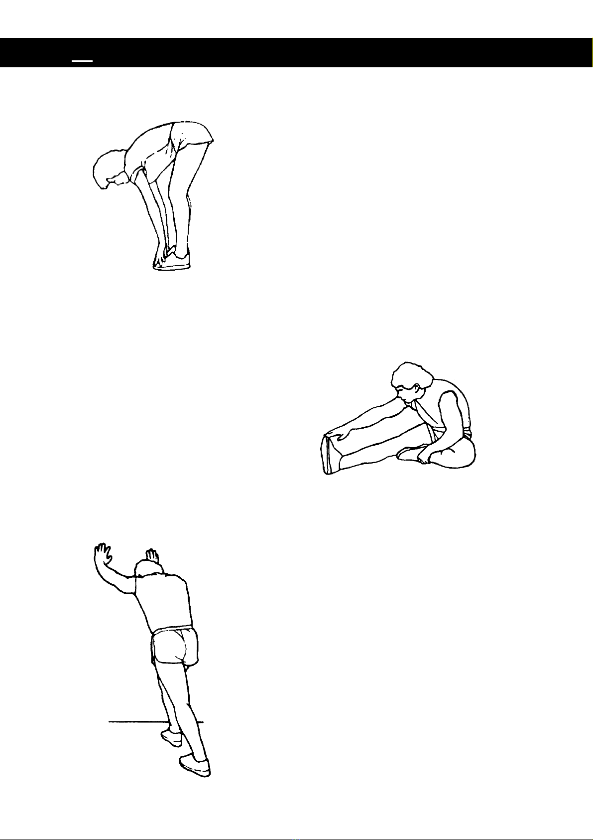
QUADRICEPS STRETCH
With one hand against a wall for balance, reach
behind you and pull your right foot up. Bring
your heel as close to your buttocks as possible.
Hold for 15 counts and repeat with left foot.
INNER THIGH STRETCH
Sit with the soles of your feet together and your
knees pointing outward. Pull your feet as close
to your groin as possible. Gently push your
knees toward the floor. Hold for 15 counts.
EN
16
HAMSTRING STRETCHES
Extend your right leg. Rest the sole of
your left foot against your right inner
thigh. Stretch toward your toe as far as
possible. Hold for 15 counts. Relax and
then repeat with left leg.
CALF/ACHILLES STRETCH
Lean against a wall with your left leg in front of
the right and your arms forward. Keep your
right leg straight and the left foot on the floor;
then bend the left leg and lean forward by
moving your hips toward the wall. Hold, then
repeat on the other side for 15 counts.
TOE TOUCHES
Slowly bend forward from your waist, letting
your back and shoulders relax as you stretch
toward your toes. Reach as far as you can and
hold for 15 counts.

D
17
WICHTIG: Lesen Sie alle Anweisungen sorgfältig durch, bevor Sie dieses Gerät
nutzen! Bewahren Sie dieses Benutzerhandbuch zum späteren Nachschlagen
auf. Die technischen Daten des Produkts können, aufgrund von Änderungen
ohne vorherige Ankündigung von dieser Ansicht abweichen.

D
18
SICHERHEITSHINWEISE
Bei der Verwendung dieses Geräts empfehlen wir die grundlegenden
Sicherheitshinweise zu beachten und die nachstehenden
Sicherheitsmaßnahmen zu befolgen. Lesen Sie alle Anweisungen, bevor Sie
das Gerät nutzen.
1. Lesen Sie alle Anweisungen in dieser Bedienungsanleitung und machen Sie
Aufwärmübungen, bevor Sie vom Gerät Gebrauch machen.
2. Vor dem Training, um Muskelschäden zu vermeiden, ist es
notwendig, Aufwärmübungen für jede Körperposition durchzuführen. Siehe Seite
über die Routine zum Aufwärmen und Entspannung. Nach der Übung, empfehlen
wir. Entspannung des Körpers zur Beruhigung.
3. Vor dem Gebrauch, prüfen Sie die Bestandteile auf Schäden und sichere
Befestigung. Das Gerät muss während des Gebrauchs auf eine ebene Fläche
aufgestellt werden. Die Nutzung einer Matte oder eines anderen Materials für
das Bedecken des Bodens ist empfehlenswert.
4. Tragen Sie geeignete Kleidung, wenn Sie das Gerät nutzen. Tragen Sie keine
Kleidung, die in den verschiedenen Teilen des Geräts verfangen werden
könnten; denken Sie daran, die Pedalriemen enger zu schnallen.
5. Führen Sie keine Wartungen oder Einstellungen durch, die nicht in diesem
Handbuch beschrieben sind. Sollten Probleme auftreten, beenden Sie die
Nutzung des Geräts und konsultieren Sie einen autorisierten Servicetechniker.
6. Verwenden Sie das Gerät nicht draußen.
7. Dieses Gerät ist nur für den häuslichen Gebrauch bestimmt.
8. Die Nutzung des Geräts ist einer einzigen Person gestattet.
9. Halten Sie Kinder und Haustiere vom Gerät während des Gebrauchs fern. Der
Freiraum für den sicheren Betrieb beträgt mindestens zwei Meter.
10. Sollten Sie Schmerzen in der Brust, Übelkeit, Schwindel, oder Atemnot
empfinden, beenden Sie sofort die Übungen und holen Sie sich einen Arzt zur
Hilfe, bevor Sie mit der Wiederaufnahme der Übungen fortfahren.
WARNUNG:Vor erstmaligem Training, konsultieren Sie Ihren Arzt.
Diese. Phase ist besonders wichtig für Menschen, die älter als 35 Jahren oder
mit Gesundheitsproblemen konfrontiert sind. Lesen Sie alle Anweisungen,
bevor Sie die Fitnessgeräte nutzen.
ACHTUNG: Lesen Sie die Anweisungen sorgfältig durch, bevor Sie von
diesem Produkt Gebrauch machen. Bewahren Sie dieses Handbuch zum
späteren Nachschlagen auf.
11. Das maximal zulässige Gewicht für dieses Gerät ist 120Kg.

D
19
LISTE DER BESTANDTEILE
Nr.
Beschreibung
Menge
Nr.
Beschreibung
Menge
001
Hauptrahmen
1
030
Mutterschutzkappe M8
4
002
Vordere Stützstange
1
031
Schwungrad Ø230x40xØ32
1
003
Hintere Stützstange
1
032
Lagerring
2
004
Zwischenhebel
1
033
Lager 6000ZZ
2
005
Sattelstange
1
034
Lagermutter I 15/16"
1
006
Sattel-Gleitstange
1
035
Lagermutter II 7/8"
1
007
Stange für Lenker
1
036
Scheibe Ø24xØ40x3.0
1
008
Lenker
1
037
Scheibe Ø23xØ34.5x2.5
1
009
U-Konsole
2
038
Sechskantmutter 7/8"
1
010
Scheibe Ø16xØ8x1.5
6
039
Kurbelwelle Ø240J6
1
011
Ringschraube M8x85
1
040
Stift M5X45
1
012
Endkappe für vordere Stützstange
2
041
Große gebogene Scheibe Ø5
1
013
Endkappe für hintere Stützstange
2
042
Stift M5X10
4
014
Große gebogene Scheibe Ø8
8
043
Horn aus Schaumstoff für Lenker
2
Ø24xØ30x550
015
Stellfuß M8
1
044
Linke Pedal YH-30X
1
016
Federscheibe Ø6
2
045
Rechte Pedal YH-30X
1
017
Stift M8x70
4
046
Endkappe für Lenker
2
018
Endkappe für Sattel-Schiebestange
2
047
Schraubenkopfabdeckung
2
(□38)
019
Stift M8x15
4
048
Runder Handgriff M16
1
020
Stift M8x20
1
049
Handpulssensor mit Kabel
L=750mm
2
021
Ringschraube M6x36
2
050
Sensorkabel L=750mm
1
022
Spannrolle Ø10xØ35
1
051
Kettenkastendeckel links
1
023
Schraube ST2.9×12
2
052
Kettenkastendeckel rechts
1
024
Schraube ST4.2×20
6
053
Buchse für Befestigungshülse
1
025
Schraube ST4.2×25
7
054
Spanndrehknopf
1
026
Kreuzzylinderkopfschraube
eingekerbt
4
055
Netzkabel L=1150mm
1
ST4.2x25
027
Sicherheitsmutter aus Stahl und
Nylon M8
6
056
Schutzbügel
1

D
20
Nr.
Beschreibung
Menge
Nr.
Beschreibung
Menge
028
Mutter M6
2
057
Distanzscheibe (Ø12x20x1.5)
1
029
Sechskantmutter M10
2
058
Hülse für Lenkerbefestigung
1
059
Sattelhülse
1
064
T-förmiger Lenkergriff (M8x55)
1
060
Gürtel PJ360 J6
1
065
Scheibe Ø12x Ø6x1.0
1
061
Sattelkissen DD-982AT
1
066
Stift M6X10
1
062
Computer
1
067
Steckdose
1
063
Sensor-Verlängerungskabel
(L=1000mm)
Table of contents
Languages:
Other TECHFIT Exercise Bike manuals


Popular Exercise Bike manuals by other brands


Reebok
Reebok Rb 310 Exercise Bike Manuel de l'utilisateur

Stamina
Stamina 15-4845 owner's manual

Keys Fitness
Keys Fitness CardioMax 700r owner's manual

cecotec
cecotec DRUMFIT CYCLE 9000 TALOS PRO instruction manual

Christopeit Sport
Christopeit Sport EMT 2200 Assembly and exercise instructions

TITAN LIFE
TITAN LIFE Athlete C55 manual