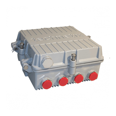
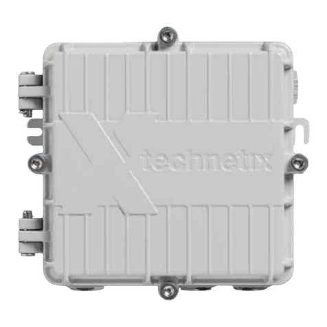
technetix DBE-1200S User manual

Contents
Precautions..............................................................................................................................................................................1
Intended audience .................................................................................................................................................................1
List of tools required ..............................................................................................................................................................1
Software ...................................................................................................................................................................................2
Modules available for the DBE-1200S ................................................................................................................................3
Chapter 1: Overview of the DBE-1200S..............................................................................................................................5
Chapter 2: DBE-1200S RF amplifier or optical node........................................................................................................6
Chapter 3: Installing the DBE-1200S amplifiers................................................................................................................11
3.1 Mounting the DBE-1200S housing................................................................................................................................................................ 11
3.2 Electrical connections ..................................................................................................................................................................................... 12
3.3 Closing the amplifier ........................................................................................................................................................................................ 13
3.4 Configuring the Power Supply Unit (PSU)................................................................................................................................................. 14
3.5 Powering up the amplifier.............................................................................................................................................................................. 15
3.6 Downstream activation ................................................................................................................................................................................... 16
3.7 Upstream activation.......................................................................................................................................................................................... 21
Chapter 4: Maintenance........................................................................................................................................................25
4.1 PSU replacement ............................................................................................................................................................................................... 25
4.2 Amplifier module replacement..................................................................................................................................................................... 26
Chapter 5: Optical node 1x1 to 3x3 .....................................................................................................................................28
5.1 General installation............................................................................................................................................................................................ 28
5.2 Downstream connection................................................................................................................................................................................ 28
5.3 Upstream connection...................................................................................................................................................................................... 29
5.4 CWDM applications.......................................................................................................................................................................................... 30
5.5 Software settings.............................................................................................................................................................................................. 31
5.6 Upgrading an RF amplifier into an optical node..................................................................................................................................... 32
5.7 Optical modules................................................................................................................................................................................................. 35
Product user manual
DBE-1200S
Technetix Group Limited04/2019 - EN/V8

104/2019 - EN/V9 Technetix Group Limited
Product user manual
DBE-1200S
1 Precautions
CAUTION
AC voltages in the range of 20 – 90 VAC (110/230 VAC local power) can be present when
power is connected to the DBE-1200S. Observe all notes and cautions in this user manual.
Opening or removing the equipment cover may expose you to dangerous voltages. Refer all
servicing to qualified service personnel only.
Electric shock can cause personal injury or even death. Avoid direct contact with dangerous voltages at
all times. Know the following safety warnings and guidelines:
■Only qualified service personnel are allowed to perform equipment installation or replacement
■Only qualified service personnel are allowed to remove equipment covers and access any of the
components inside the chassis
■This equipment may have multiple power sources. Be sure to disconnect all power sources before
working on this equipment
Intended audience
The DBE-1200S User manual is intended for network engineers and technicians responsible for planning,
configuring, installing and testing the Technetix DBE-1200S amplifier. Installers should have a working
knowledge of coaxial cable systems and cabling practices and should heed all safety warnings.
List of tools required
The following tools and supplies are required when installing a DBE-1200S:
■A 1/2" wrench for the lid bolts
■A set of crosshead (Philips) screwdrivers
■A pair of linesman’s pliers (only needed if changing the diplex filters) or a DBGB-A-1 digital broadband
diplex grabber tool
■A torque wrench
■The appropriate bolts/screws/washers for mounting the DBE-1200S (see Chapter 3)
■The appropriate USB cable:
■A USB A type for the DBDCM-A-1 FSK module (for local control/ALSC)
■A USB A type for the DBDCM-B-2 DOCSIS control module (DOCSIS cabling is included
in transponder set)
■A USB A type for the T-BOX (Bluetooth/Wi-Fi communication)
The connector on the other side of the cable will depend on the device you are using.

204/2019 - EN/V9 Technetix Group Limited
Product user manual
DBE-1200S
USB cables available from Technetix:
■19005966 USB MICRO OTG (3.9" – mini USB)
■19005965 USB A-male to B-mini 2M
Software
The software you require to configure a DBE-1200/DBE-1200S depends on the device you are using to connect to the
modules within the amplifier:
■Laptop – BLL software. The software is compatible with Windows OS
■Android – BLA software. The software is compatible with Android version 4.1 or higher and USB host.
Note: We refer to BLx to identify BLL software for use on a laptop and BLA software for use on an Android device.
To install the BLL software on a Windows operating system, complete the following steps:
1. Remove any previous versions before installing the latest version (remove full stop)
2. Click on the BLL Setup icon
3. Follow the installation directions displayed on the computer
To install the BLA software on an Android phone or tablet, complete the following steps:
1. To ensure the device will allow unknown sources:
a. Go to Settings > Lock screen and security
b. Turn on the Unknown sources toggle switch
2. To copy the “BLA vx.x.apk”file to the Android device:
a. Go to Applications > Settings > Wireless and Network > USB Settings
b. Select Mass storage
c. Connect the phone/tablet to your PC
d. The drives of the phone will appear in file explorer
e. Copy the .apk file to a suitable place on the phone/tablet
3. Go to applications > my files
4. Browse to the .apk file
5. Click the BLA .apk file
6. Select “OK”to install
7. Once installed you can select ‘open’ or ‘done’
8. The Technetix BLA shortcut can now be found with all the other applications on your device
■19010840 USB A-male to A-male 16.4 ft
■19007113 USB A-male to B-mini 16.4 ft

304/2019 - EN/V9 Technetix Group Limited
Product user manual
DBE-1200S
Modules available for the DBE-1200S
Upstream (US)
DBUS-C-1 Main module: 204 MHz US amplifier 26 dB gain and IDS
DBUS-D-1 Bridger module: 204 MHz upstream amplifier 26 dB gain and IDS
Downstream (DS)
DBDS-B-4-1 Main: 1.2 GHz DS amplifier 44 dB - 49 dbmV output
DBDS-B-4-ET Main: 1.2 GHz DS amplifier 44 dB - 49 dbmV output – ET:25 dB tilt
DBDS-B-5-1 Main: 1.2 GHz DS amplifier 38 dB - 49 dbmV output
DBDS-B-6-1 Main: 1.2 GHz DS amplifier 32 dB - 49 dbmV output
DBDS-B-7-1 Main: 1.2 GHz DS amplifier 44 dB - 53 dbmV output
DBDS-B-7-ET Main: 1.2 GHz DS amplifier 44 dB - 53 dbmV output ET:25 dB tilt
DBDS-F-2 Bridger: 1.2 GHz downstream amplifier 44 dB - I2C
DBDS-F-5-1 Bridger: 1.2 GHz downstream amplifier 44 dB - I2C - 53 dBmV output
Control Module
DBDCM-A-1 AGC/ALSC, FSK
DBDCM-B-2 AGC/ALSC, DOCSIS transponder compatible
DBDDM-A-1 DOCSIS 3.0 transponder
DBDDM-B-1 EuroDOCSIS 3.0 transponder
Optical Modules
R
DBRX-A-1 Optical 1.2 GHz downstream receiver, 53 dBmV output
TX
DBTX-A-1 Optical upstream transmitter module. Holds up to 2 DBLB optical transmitters
DBLB-31-3D-1 Optical 204 MHz transmitter plug-in, 1310 nm, DFB, 3 dBm output, SC/APC
DBLB-55-3D-1 Optical 204 MHz transmitter plug-in, 1550 nm, DFB, 3 dBm output, SC/APC
DBLB-BP-1 Bypass laser board for DBTX-A-1 (insert in second slot if second laser is not installed)
DBLB-CB-1 Combiner board to combine two upstream RF signals into a single laser

404/2019 - EN/V9 Technetix Group Limited
Product user manual
DBE-1200S
Fiber Trays
DBE-FT-A-1 Fiber management for DBE cabinet
DBES-FT-A-1 Fiber management for DBE strand mount
Diplexers A range of field replaceable, plug-in diplex filters:
DBDIP-01-W 65/85 MHz diplexer
DBDIP-02-W 85/105 MHz diplexer
DBDIP-03-W 204/258 MHz diplexer
DBDIP-04-W 42/54 MHz diplexer
DBDIP-05-W 85/102 MHz diplexer
Power Supply
DBPSU-07-1 DBE 90 W POWER SUPPLY 90 VAC

504/2019 - EN/V9 Technetix Group Limited
Product user manual
DBE-1200S
Chapter 1: Overview of the DBE-1200S
The Technetix DBE-1200S strand mount amplifiers and optical nodes are an innovative ‘crossover’ design which provides a
field upgradeable solution to deep fiber/fiber to the last amplifier (FttLA). Its RF function can be configured for use as a 1x1 up
to 3x3 or as an RF/optical hybrid as a single, dual, or triple output device. The amplifier provides reverse path transmission with
a hybrid amplification stage.
Forward and return path attenuation can be adjusted with electronic attenuators through software control. Electronic equalizers
can be adjusted via software for forward and return path equalization. Cable simulation can be implemented by inserting an
appropriate JXP module (available in 1 to 7 and 9 to 15 dB tilt values for applications up to 1.2 GHz).
The DBE-1200S has a highly ecient long-life switched-mode 90 W power supply (DBPSU-07-1) to provide power, with ample
margin, to the internal electronics.
Surge arrestors at the input and output ports protect the RF circuits in the event of lightning or mains power surges.
In the DBE-1200S these protection devices are field replaceable plug-in modules.
Benefits
■Full digital control and setup with user selectable integrated Automatic Temperature Control (ATC), Automatic Gain Control
(AGC) or Automatic Level and Slope Control (ALSC)
■Improved intermodulation distortion performance - innovative GaN technology operates to 1218 MHz
■Energy ecient hybrid technology provides more gain with the same power consumption
■Flexible and modular to meet changing network needs
■Technetix CPD Safe®technology and surge protection mean fewer reported faults, improved customer service
and a reduction in truck rolls
* Note: Common Path Distortion (CPD)
■On-board ingress detection facility provides an option to apply -6 dB or -40 dB of return path attenuation either by; (1)
local control through a USB connection in conjunction with the software, or (2) via a simple Frequency Shift Keying (FSK)
communications protocol via an FSK transmitter in the headend, or (3) through Simplified Network Management Protocol (SNMP)
control when the amplifier/node is outfitted with a Data Over Cable Service Interface Specification (DOCSIS) transponder.

604/2019 - EN/V9 Technetix Group Limited
Product user manual
DBE-1200S
Chapter 2: DBE-1200S RF amplifier or optical node
1
17
15
16
12
14
11
12
1548732561012
15
13
14
9
15
Item No. Description
1 Removable power supply
2 Main upstream amplifier module (one place)
3 Upstream bridger amplifier module (one place)
4Upstream auxiliary plug-in JXP attenuator location
(can be used for other types of JXP plug-ins) (three places)
5 Digital control module
6 Digital control module USB connection port
7 Main downstream amplifier module (one place)
8 Downstream bridger amplifier modules (two places)
9Downstream cable simulator JXP location
(can be used for other types of JXP plug-ins) (three places)
Item No. Description
10 Input diplex filters; 42/54, 65/85, 85/102, 85/105
and 204/258 options available (one place)
11 Output diplex filters;42/54, 65/85, 85/102, 85/105 and 204/258
options available (three places)
12 Fuses (four places)
13 Input -20 dB test point (omnidirectional) (one place)
14 Output downstream -20 dB test point (upstream injection -20 dB
test point) (three places)
15 Field replaceable surge arrestors (four places)
16 Optional local powering port (mains or 65 VAC)
17 Optional DOCSIS Transponder
(Requires DBDCM-B-2 DOCSIS Control Module and cables)
DBE-1200S RF amplifier

704/2019 - EN/V9 Technetix Group Limited
Product user manual
DBE-1200S
Block diagram for RF configuration
Power supply
Local power
input port
Port 2Port 3
Auto fuses
-20 dB
testpoint
Port 1
-20 dB
testpoint
-20 dB
testpoint
-20 dB
testpoint
DOCSIS
transponder
DBDCM-X-X control module
DBDS-B-x-xx downstream
DBDS-F-x-xx
DBDS-F-x-xx
DBUS-D-1
DBUS-C1 upstream module
-6dB
off
-6dB
off
Digital control
-6dB
off
-6dB
off
Digital control

804/2019 - EN/V9 Technetix Group Limited
Product user manual
DBE-1200S
DBE-1200S optical node
Fiber
management
tray
Downstream optical
receivers
Upstream optical
transmitters

904/2019 - EN/V9 Technetix Group Limited
Product user manual
DBE-1200S
Block diagram for Optical Node
Power supply
Local power
input port
Port 2Port 3
Auto fuses
Port 1
-20 dB
testpoint
-20 dB
testpoint
DBDCM-X-X control module
DBRX optical receiver
O
E
DBRX optical receiver
O
E
DBRX optical receiver
O
E
DBTX-A-1 optical transmitter
O
E
DBTX-A-1 optical transmitter
O
E
O
E
0dB
TP
0dB
TP
0dB
TP
-20 dB
testpoint
DOCSIS
transponder

1004/2019 - EN/V9 Technetix Group Limited
Product user manual
DBE-1200S
DBE-1200S electrical/optical hybrid
In a hybrid configuration all of the upstream and downstream connections to the headend are through fiber. Here is an
example hybrid configuration of the DBE-1200S with one upstream optical transmitter module with two lasers, and a second
upstream optical transmitter module with one laser, and one downstream optical receiver feeding two downstream bridger
amplifier modules. Other configurations are also possible. All upstream data inputs can be combined on one laser transmitter.

1104/2019 - EN/V9 Technetix Group Limited
Product user manual
DBE-1200S
Chapter 3: Installing the DBE-1200S amplifiers
3.1 Mounting the DBE-1200S housing
There are two options for mounting the DBE-1200S amplifier:
Strand mount
Two messenger clamps are located on the top of the housing and are secured with 5/16" x 18 threads per inch stainless steel
bolts. These should be torqued to 0.37 ft*lb (0.5 N*m).
Rear mounting direct to cabinet back panel
For mounting directly onto a cabinet back panel, the rear 5/16"-18 UNC bolt holes can be used with four 5/16"-18 UNC
threaded bolts (see following picture). When using this method of mounting, make sure that the bolt’s threads will not protrude
any more than 5/16" (8 mm) in length through the back board that the amplifier will be mounted onto. The total bolt length
should be 5/16" (8 mm) + back board thickness + washer thickness.
Mounting holes on the centerline of the back of the DBE-1200S housing are spaced 12-1/16" on-center.
They are 5/16"-18 UNC x 11/32" (9 mm) deep.

1204/2019 - EN/V9 Technetix Group Limited
Product user manual
DBE-1200S
3.2 Electrical connections
1. There is a ground contact on the left side of the housing to connect a ground wire. A crosshead (Phillips)
screwdriver should be used to tighten the ground screw to a torque value of 0.37 ft*lb (0.5 N*m).
Grounding screw located
on the side of the housing.
2. To install the coaxial cable, cut the connector pins to a length of 1.1" (28 mm) for threaded connectors
as shown below. When using 5/8"-18 UNC threaded connectors and 5/8" reducing rings, add 7/64" (2.5 mm)
to the connector pin length = 1.2" (30.5 mm).
3. Tighten the connectors into the housing in accordance with the connector manufacturer’s specification. The maximum
torque force for the coaxial connector and 5/8" adapter ring is 14.75 ft*lb (20 N*m).

1304/2019 - EN/V9 Technetix Group Limited
Product user manual
DBE-1200S
4
1
56
2
3
3.3 Closing the amplifier
The housings have a woven wire RF gasket and a rubber gasket to provide a seal between the housing base and lid.
The RF gasket provides shielding to prevent RF ingress/egress and the rubber gasket keeps out water. The rubber
gasket should be replaced if it is damaged.
To close the amplifier lid, first tighten the six lid securing bolts hand tight. Next, using a 1/2" wrench, or a cross head (Phillips)
screwdriver, hand tighten the lid bolts in the sequence shown in the figure:
1- bottom left bolt at hinge
2- top right bolt
3- bottom right bolt at hinge
4- top left bolt
5- left side bolt
6- right side bolt
Then, using a torque wrench set to a torque value of 3.7 ft*lb (5 N*m), go around again in sequence and tighten
to the final torque setting.
Following this sequence will ensure:
1. The rubber gasket between the lid and the amplifier housing is sealed correctly, providing a sound, watertight seal to
prevent water ingress.
2. A good RF seal between the RF gasket in the lid and the amplifier housing to prevent RF ingress/egress.
3. A good lid to housing contact for the dissipation of amplifier heat. The lid acts as a radiator when it is correctly
secured, keeping the amplifier operating temperature within operating limits when installed as recommended.

1404/2019 - EN/V9 Technetix Group Limited
Product user manual
DBE-1200S
3.4 Configuring the Power Supply Unit (PSU)
The DBE-1200S has the following power supply options:
1. Local powering is achieved on the RF input port using a power inserter.
2. Remote powering through the External Power port (see item 16 on page six). Maximum AC power passing = 10 Amps.
See page Chapter 4.1 for removal/installation of PSU unit.
Fuses
Referring to the network design documentation, remove any fuses not required for passing power.
Remove fuses on the output ports of the
DBE-1200S if it is not necessary to carry power. Ext. power port

1504/2019 - EN/V9 Technetix Group Limited
Product user manual
DBE-1200S
3.5 Powering up the amplifier
1. After any bench pre-configuration required by the network design and once the amplifier is mounted into the network
location, temporarily remove the fuses. Connect the RF cables to the relevant RF ports and connect the earth/grounding
wire (in accordance with local electrical installation regulations) on the right-hand side of the housing.
2. Using a true RMS digital voltmeter, confirm AC power is present on the port where incoming power is present in
accordance with the network design drawings. The voltage should be within the amplifier specification and thenetwork
design drawing calculation.
3. Install the input port fuse per the network design drawings and ensure that it is fully inserted into the fuse holder
for incoming AC power. Then check that the amplifier DBDCM module LED (DBDCM-A-x = red, DBDCM-B-x = green)
is illuminated.
The LED on the control module indicates
that the DBE-1200S amplifier is powered
up when it is illuminated.

1604/2019 - EN/V9 Technetix Group Limited
Product user manual
DBE-1200S
3.6 Downstream activation
Connect a spectrum analyzer to the input -20 dB test point, then measure and record the RF pilot frequencies’ input levels as
per the design drawings.
DBE-1200S input testpoint
Note: Ensure all amplifier ports are connected to a 75 Ω terminated load so that the RF test instrument readings are correct.

1704/2019 - EN/V9 Technetix Group Limited
Product user manual
DBE-1200S
Electronic setup downstream
Note: For advanced settings and configurations, please refer to the latest release of our BLL, BLA, or T-Box
Using a laptop with the Technetix BLL software installed or an Android device with the Technetix BLA software installed,
connect the laptop or Android device to the amplifier through the USB connection.
Next, carry out the following steps:
Note: Steps 1 to 3 can be completed on the bench if the amplifier is powered up before it is deployed.
1. The BLx should connect with the amplifier control module automatically when the software is running and the computer
is connected to the control module via the USB cable. To connect manually: with the BLx software running, click on Scan
Bus at the top left of the application screen.
This enables the BLx application to connect to the DBDCM control module. Once the communication with the amplifier
is established, the amplifier type name will appear at the top left of the application. All amplifier operating parameters
and settings (equalization and attenuation, and ingress detection switch settings) will be displayed.
USB cable connected to the control module in the DBE-1200S.
Scan Bus Icon

1804/2019 - EN/V9 Technetix Group Limited
Product user manual
DBE-1200S
BLx Screen when connected to DBE-1200S optical node (hybrid)
2. Set the Amplifier Type (End, Single, Group, Trunk
etc.) to its respective application followed by the
Diplexer Type and the upper equalizer hinge point,
End Frequency.
Once these values are set in the application, click on
Send to amp (on the bottom right of the screen, at
the left side of the control panel) to set these values
electronically.
3. The downstream Inter-stage equalizer and Inter-
stage attenuator can be set as required by the
network/system design documentation in two ways.
You can set them in the amplifier schematic
inter-stage tabs or in the table to the right of the
application screen (see the screen shot below).
Once the values are set in the application, click
on Send to amp to set these values electronically.
Table of contents
Other technetix Amplifier manuals

technetix
technetix LINDSAY BROADBAND LMDA3726 Series User manual
technetix
technetix DBC-1200 User manual
technetix
technetix AIMA3000.EDFA Operational manual
technetix
technetix AIMA3000.RPAS Operational manual
technetix
technetix AIMA-FPAS Operational manual
technetix
technetix DBD-1200 User manual
technetix
technetix DBC-1200 User manual
technetix
technetix EDFA-R Operational manual
technetix
technetix DBC-1200S User manual
technetix
technetix AIMA3000.FPAE Operational manual

