technetix LINDSAY BROADBAND LMDA3726 Series User manual

LMDA3726 Series 1.2 GHz Compact MDU Amplifiers
Installation Manual
Page 1 of 3
Lindsay Broadband’s exclusive, compact, multiple-dwelling unit (MDU) amplifier delivers reliable performance supporting DOCSIS®3.1 frequencies to 1.2 GHz.
The LMDA3726 series of amplifiers is designed for advanced HFC network installations in apartment buildings, hotels, schools, hospitals and similar facilities having
high RF amplification requirements. Designed with high gain, this two-way, upgradeable amplifier uses the latest 1.2 GHz GaAs-FET push-pull technology to provide
superior distortion performance and low noise. This amplifier can be mounted directly to a wall, and further reduces operational costs with increased heat dissipation
and low power consumption.
FEATURES
•Fully meets the requirements of DOCSIS 3.1
•Downstream frequency bandwidth extends to 1.2 GHz
•Operating Temperature: -30°C to +55°C (-22°F to +131°F)
•Forward gain 37 dB; reverse gain 26 dB
•-20 dB external test points
•GaAs-FET push-pull technology for high output levels with low distortions
•Variable attenuators are designed to include a potentiometer - digital
signal attenuator combination to match excellent return loss performance
•SCTE compliant F-type connectors
•6 kV surge protection on all ports
•Powering Options: HFC 40-90 VAC, 24 VDC, 100-240 VAC
•Finned, diecast aluminum housing for heat dissipation
PRODUCT OVERVIEW
Part # Power Socket Type Frequency Range
LMDA3726-A-xx 100-240 VAC (N. America) 5-42 MHz / 54-1220 MHz
5-85 MHz / 102-1220 MHz
5-204 MHz / 258-1220 MHz
LMDA3726-B-xx 100-240 VAC (Europe)
LMDA3726-C-xx 40-90 VAC (HFC-powered)
CAUTION
Risk of electric shock. Do not open.
No serviceable parts inside. Refer servicing to qualified service personnel.
WARNING: To prevent shock hazard, do not expose this unit to rain or moisture. This apparatus shall not be exposed to dripping or splashing
water and no objects filled with liquids, such as vases, shall be placed on the apparatus.
WARNING: This product is a Class-I construction. Please ensure a connection to power source includes a protective earthing connection.
Remember to replace cover after adjusting. Cover must be in place for CE, safety and protection.
FUNCTIONAL SCHEMATIC

LMDA3726 Series 1.2 GHz Compact MDU Amplifiers Installation Manual
Page 2 of 3
SPECIFICATIONS
Parameter Specification
Forward Reverse
Bandwidth
(1)
54-1220 MHz 5-42 MHz
102-1220 MHz 5-85 MHz
258-1220 MHz 5-204 MHz
Technology GaAs
Average Full Gain 37 dB 26 dB
Flatness < ± 1 dB
Return Loss In -16 dB (< 1 GHz) -14 dB
Out -14 dB (1-1.2 GHz) -14 dB
Test Points Fwd In/Rev Out (bi-directional) -20 dB
Fwd Out/Rev In (bi-directional) -20 dB
Gain Control Variable Attenuator
(2)
0-20 dB In/Mid 0-20 dB In/Out
Slope Control Variable Attenuator
(2)(3)(4)
0-18 dB In/Mid 0-15 dB In/Out
Forward Distortions: 33/48 dBmV output level (72 NTSC analog channels plus 111 equivalent digital 256 QAM channels, 102-1220 MHz)
(5)(6)
CTB On CH 78 -67 dBc
CSO On CH 78 -70 dBc
Reverse Distortions: 52 dBmV flat output, 13 & 19 MHz carriers according to ANSI SCTE 1152019
(6)
DTO @ 7 & 25 MHz -68 dBc
DSO @ 6 & 32 MHz -75 dBc
Noise Figure With 0 dB Jumpers 8 dB 6 dB
Recommended RF Input Level 9 dBmV (single)
13 dBmV (cascaded)
Group Delay
CH 2 (55, 25-58.83 MHz) < 35 ns
CH 98 (109, 25-112.83 MHz) < 35 ns
CH 15 (259, 25-263.08 MHz) < 35 ns
204-203 MHz / 84-85 MHz / 42-54 MHz / 5-6 MHz < 30 ns
Power, Environmental & Physical
Hum Modulation -70 dBc
RFI Isolation -100 dBc
Surge Withstand IEEE C62.41-Cat B3, Combination Wave, 6 kV, 3 kA
Powering 24 VDC / 40-90 VAC / 100-240 VAC / HFC 40-90 VAC
Power Consumption 10 W
Enclosure IP54 category, diecast aluminum
Operating Temperature -30°C to +55°C (-22°F to +131°F)
Dimensions (H x W x D) 6.4”H x 6.6”W x 2.5”D (16.2H x 16.7W x 6.3D cm)
Weight 2.7 lb (1.2 kg)
NOTES:
(1) Band selection by factory, arranged on board diplexers
(2) Variable attenuators & equalizers. Potentiometer & digital signal attenuator combination
(3) Onboard EQ circuit on forward path. Slope (dB) is selected via variable attenuators
(4) Onboard EQ circuit on return path. Slope (dB) is selected via variable attenuators
(5) 0.5 dB maximum roll off at 105 & 258 MHz
(6) NTSC or virtual level, digital levels are 6 dB lower
LMDA3726-A-81
(front angled view)

LMDA3726 Series 1.2 GHz Compact MDU Amplifiers Installation Manual
NOTE TO CATV SYSTEM INSTALLER
This reminder is provided to call the CATV system installer’s attention to Article 820-40 of the NEC that provides guidelines for proper grounding and, in particular,
specifies that the cable ground shall be connected to the grounding system of the building, as close to the point of cable entry as practical.
INSTALLATION & SETUP GUIDELINES
1. Gain and cable slope controls are reachable under the housing lid. Refer to layout scheme on the cover under the housing lid for controls adjustment.
2. This product is shipped with default 0 dB positions for all variable attenuator and equalizer sub-boards.
3. Band selection is made by factory production. Please check ordering information below and contact factory for upstream/downstream band selections other than
the factory default.
4. Before applying power to the amplifier make sure that the forward input level to the amplifier is not too high or damage to the amplifier might occur.
5. Please check that the forward variable equalizers and mid-stage variable pad are set to 0 dB as factory default values.
6. Now apply power to the amplifier and measure the amplifier forward output level at the 20 dB output test point. If it is very low then adjust the value of the input
variable attenuator until the desired output level is reached at the highest operating frequency. Remember that the level measured at the test point is 20 dB lower
than the real signal level.
7. Rotate the equalizer potentiometer in order to activate the equalization function to adjust the output level to be flat across the full bandwidth. The input signal level
will now be flat too. Under this condition there will be best CNR across the full bandwidth.
8. Now rotate the equalizer potentiometer, in order to activate the onboard equalization function, into the forward mid-stage equalizer socket to get as close as
possible to the desired output signal slope. The desired output slope is determined by your system design. Consult your system planner or your system maps for
this information.
9. If you are having trouble obtaining the expected output levels then check the input test point to verify that the levels are as expected at the input of the amplifier.The
forward set-up is complete.
10 For the reverse path, inject into the forward output test point test carriers with the system design input signal level plus 20 dB (because the test point has 20 dB
loss) at each end of the upstream band.
11. Verify that the upstream reference test point (note: this is commonly called the “X point” and it is measured at your node, or optical receiver, or at the first
downstream amplifier - consult with your system designer) has the proper upstream output signal levels. If it does not, rotate the variable attenuator and equalizer to
the desired levels.
12. Record the in/out operating levels in this station.
INSTALLATION PRECAUTIONS TABLE
Precautions Requirement
Facilitate service and maintenance Allow a minimum of 35 in. (90 cm) clearance in front of the equipment rack(s)
Avoid direct heating or air conditioning If unavoidable, use deflector plates
AC power source outlets Locate equipment near sufficient outlets to provide power for test equipment and power tools
Rack support Make certain rack supports are sufficiently rigid to support rack(s)
Building leakage Beware of dripping water onto equipment from leaky roofs, waveguide roof entries, and cold water pipe condensations
ORDERING INFORMATION
Power Socket Type Frequency Range
LMDA3726 -x-xx
A = 100-240 VAC (N. America) 45 = 5-42 MHz / 54-1220 MHz
B = 100-240 VAC (Europe) 81 = 5-85 MHz / 102-1220 MHz
C = 40-90 VAC (HFC-powered) 22 = 5-204 MHz / 258-1220 MHz
2-2035 Fisher Dr, Peterborough, ON K9J 6X6 Canada
+1.705.742.1350 • 1.800.465.7046 • support@lindsaybb.com • lindsaybb.com
All information is subject to change without notice.
Rev. 10/22 (LBB0471) • Page 3 of 3
© 2022 Lindsay Broadband - a division of Technetix group. All rights reserved. Printed in Canada. Non-Lindsay Broadband product
marks, service marks, and company names in this document are the property of their respective owners.
Other technetix Amplifier manuals
technetix
technetix AIMA-FPAS Operational manual
technetix
technetix DBC-1200 User manual
technetix
technetix AIMA3000.FPAE Operational manual
technetix
technetix DBC-1200 User manual
technetix
technetix AIMA3000.EDFA Operational manual
technetix
technetix DBC-1200S User manual
technetix
technetix AIMA3000.RPAS Operational manual
technetix
technetix DBD-1200 User manual
technetix
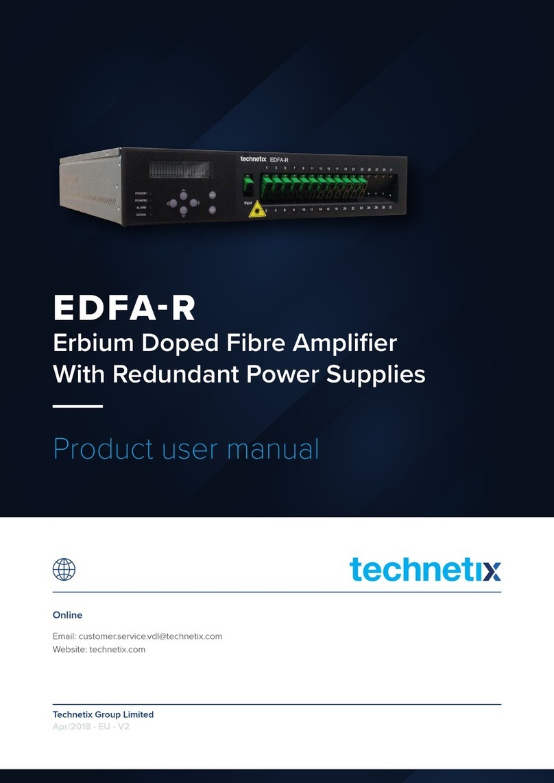
technetix EDFA-R Operational manual
technetix
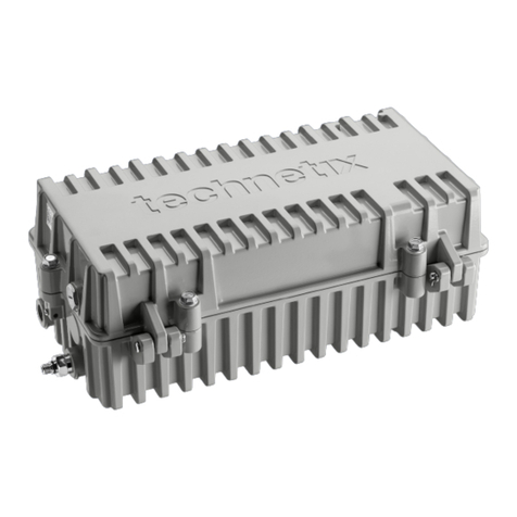
technetix DBE-1200S User manual
