Techniks SHRINKPRO User manual
www.techniksusa.com
Model 00500-M
ShrinkPRO Quencher
SHRINKPRO MACHINE
OPERATIONS MANUAL
COMPLETE INSTALLATION AND TROUBLESHOOTING GUIDE
Model 00600-M
ShrinkPRO
Techniks Inc. 9930 E. 56th St. Indianapolis, IN 46236 | 800.597.3921 | www.techniksusa.com | [email protected]
Techniks is a proud member of Techniks Tool Group. Connect with Techniks Tool Group
1
The Model 00500-M and the Model 00600-M have been constructed using the latest technology and are
extremely safe and easy to operate. Despite that, there is still some danger if these units are operated
incorrectly and/or by untrained personnel.
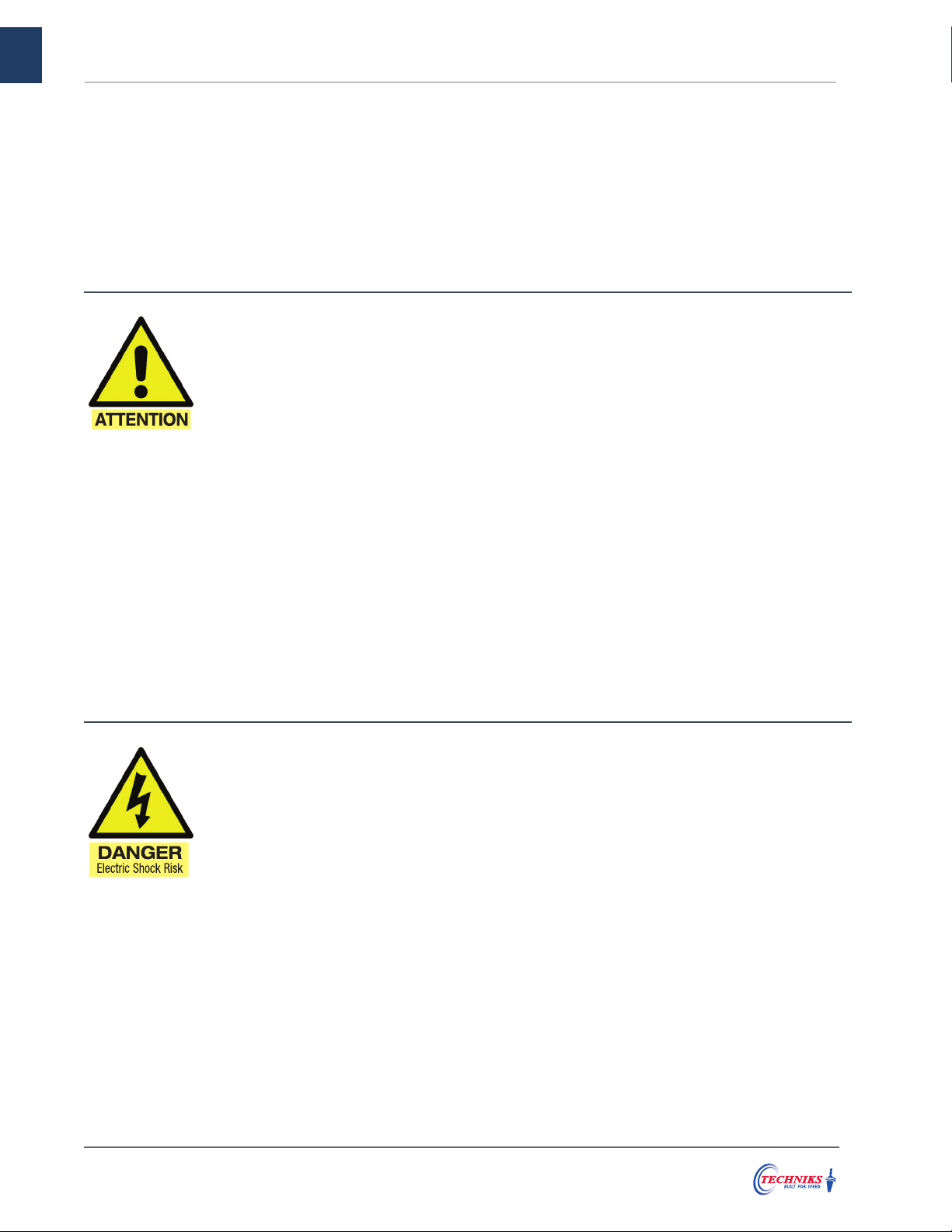
Pay particular attention to the following Cautions and Warnings marked with the “Attention” and “Danger”
symbols. Failure to follow safe operating practices may cause injuries, death, or damage to the machine,
and may void your manufacturers’ warranties.
• Before attempting to use the unit you must have
read and fully understood this Owners Manual.
Keep this Owners Manual within easy reach of
operating personnel.
• Visually inspect the unit, power cord, and
accessory items for any signs of wear or
damage before operating the unit. Do not use
the unit if there is any sign of damage, or if the
unit is not performing normally.
• Never operate the machine without the correct
induction stop ring in place on the induction
head. Do not allow any part of the induction
head to contact the toolholder or cutting tool
during operation or damage to the machine may
occur.
• Do not wear rings, bracelets, or other metallic
objects while operating the machine. Metallic
objects may heat up very quickly when near the
induction head during operation.
• Use the provided thermal insulated glove
whenever handling tools or toolholders. Never
try to handle hot tools or toolholders until the
cooling cycle is complete.
• If the machine is moved from a cold environment
to a warm one, wait two hours before operating
to prevent condensation build-up from causing
electronic system errors.
• Persons with heart pacemakers may not
operate the machine, and must maintain a
minimum safe distance of 6 feet (2 meters)
from the machine at all times.
• Cutting tools have sharp edges. Handle with
caution.
• Operating the unit while improperly connected
or at the wrong voltage may damage the unit
and could possibly cause death or injury.
• Position the power cord so it cannot be damaged
by fork trucks or other equipment, or cause a
tripping hazard for personnel.
• Do not operate the machine in a wet environment
where exposure to coolant or spills are likely
to occur. Electric shocks or damage to the
machine may occur.
• Never operate the machine around flammable
materials, or fumes. Do not use flammable
liquids or aerosols to clean toolholders. Never
expose the machine or hot tools to combustible
materials.
• Never open the machine or attempt repairs
or you will VOID the manufacturer’s warranty.
Dangerous residual voltage is inside that may
cause death or injury.
• Unauthorized modifications or changes
to the ShrinkPRO machine will VOID your
manufacturer’s warranty. Do not try and service
your unit yourself. Techniks can provide any
necessary repairs or maintenance. Do not
modify or disable the built-in safety features of
the machine.
• Turn off the power switch and disconnect the
power cord from the outlet before cleaning,
servicing, or storing the unit.
Make sure you read, understand and follow these Cautions and Warnings, as well as the complete technical notes,
setup and operation instructions before installing and using your machine.
IMPORTANT - CAUTIONS & WARNINGS

2
Satisfaction guaranteed on all our CNC tooling solutions | www.techniksusa.com
IMPORTANT – TECHNICAL NOTES
POWER REQUIREMENTS
ShrinkPRO Models 00500-M and 00600-M have been designed to operate on 480VAC 3 phase power.
The maximum power output exceeds 22,000 watts.
NOTE: Do not activate the heat controls without a toolholder in position.
AUDIBLE FEEDBACK
During operation, ShrinkPRO machines power source generates an audible feedback tone that changes
frequency depending on the toolholder size and temperature. It is not unusual to hear a pitch change as
the toolholder temperature increases. Do not be alarmed if you hear this tone as it is normal.
SHRINKFIT TOOLHOLDERS
Techniks ShrinkPRO machines make it easy and safe to perform shrink fit tool changes without causing
damage to the toolholder or cutting tool, as long as the machine is correctly installed and proper operating
procedures are followed.
ShrinkPRO machines are designed to work best with Techniks shrinkfit toolholders made from H13 tool
steel with bore diameters from 1/8” to 1-1/4” (3mm to 32mm). They are designed for shrink fitting tools
with carbide shanks. Tool shank diameter tolerance is critical. At least an H6 tolerance is advised for
optimum performance.
Make sure toolholders are clean and free from defects before inserting the tool in the toolholder. If debris
or a burr is inserted into the toolholder with the tool, tool-life may be reduced. Damage to the tool or
toolholder may also occur as the tool may be difficult or impossible to extract.
NOTE: Toolholders must be at room temperature before attempting to extract the cutting tool.
CUTTING TOOLS
Cutting tool shanks must be perfectly clean and free from burrs, scoring, or any damage. Any imperfections
in the shank can cause the cutting tool to lodge permanently in the toolholder. Burnished shanks can slip
in Shrink Fit holders under some conditions. Sand blasting the cutter shanks has improved the holding
power.
Techniks ShrinkFIT holders are made of H13 tool steel, tempered at >1000˚F. Heating a toolholder to or
above temper point will permanently damage the holding power of the toolholder. Never use an alternate
heat source on shrink fit toolholders or damage to the toolholder and cutting tool may occur.

3
00600-M PARTS IDENTIFICATION & MACHINE REQUIREMENTS
Model 00600-M ShrinkPRO
width 20” x depth 20” x height 37” - Weight: 84 lbs
Induction Head
Pedestal & Pedestal Ring
Touch Screen
Power Switch
NPT Air Inlet (on back)
MACHINE IDENTIFICATION
FEATURES
• Induction coil technology enables
tool changes in 3-6 seconds
• Easy to use touch screen design
• Heating time is automatically set
by tool diameter
• Cooling cycle uses shop air
PRODUCT SPECS
1
1
3
5
2
4
2
3
4
5
toolholder seats
induction ring insulated glove
rated to 500˚ F / 260˚ C
Part No. Tool Diameters Power L x D x H Ship Wt.
00600-M 1/8” -1-1/4” 480V, 30A, 3 phase 20” x 20” x 37” 84 lbs
Part No. Description
00165 Induction Ring (3 - 5mm shanks)
00166 Induction Ring (6 - 12mm shanks)
00167 Induction Ring (14 - 20mm shanks)
00168 Induction Ring (25 - 32mm shanks)
00600-9006 Tool Holder Adapter – HSK63/HSK100
00600-9002 Tool Holder Adapter – 40 taper
00600-9003 Tool Holder Adapter – HSK40
00600-9004 Tool Holder Adapter – HSK50
00600-9005 Tool Holder Adapter – 30 taper
00600-9006 Tool Holder Adapter – PSC6
26139-L Thermal Insulated Glove
EACH SHRINKPRO AND QUENCHER SHIPS WITH:
REQUIREMENTS:
• Electrical Supply: 480 VAC,
3 phase, 30 amp connection
(recommended).
• 50/60 Hz. Power output is 22,000
watts. NEMA L16-30R receptacle.
• Air Supply: 90 psi supply of dry
shop air. The use of an in-line
filter is required.

4
Satisfaction guaranteed on all our CNC tooling solutions | www.techniksusa.com
00500-M PARTS IDENTIFICATION & MACHINE REQUIREMENTS
FEATURES
• Induction coil technology enables
tool changes in 3-6 seconds
• Easy to use touch screen design
• Heating time is automatically set
by tool diameter
• Coolant bath and air-drying system
cools tools in under 30 seconds
PRODUCT SPECS
Quencher features a liquid cooling
cycle that is 250% FASTER than
air-cooled units.
Model 00500-M ShrinkPRO Quencher
width 36.75" x depth 24" x height 71" - Weight: 292 lbs
MECHANICALS
Pedestal Speed Flow Controls
Mechanical Access Door
Coolant Flow Bypass Control
Coolant Flow Control
Air Pressure Regulator
Coolant Drain Valve
3
1
5
4
2
6
1
2
3
4
5
6
MACHINE IDENTIFICATION
REMINDER: Always use the supplied insulated glove and exercise
caution when handling toolholders. All personnel should be clear of the
machine before starting the tool change or Quench cycle. Never touch
any toolholders that are not properly cooled. The Quenching Time and
coolant flow must be set to provide adequate cooling time to protect
personnel from injury caused by improperly cooled toolholders.
Part No. Tool Diameters Power L x D x H Ship Wt.
00500-M 1/8” -1-1/4” 480V, 30A, 3 phase 37” x 24” x 71” 660 lbs
Part No. Description
00500-C 1 Gallon Quencher Coolant
EACH QUENCHER SHIPS WITH:
5
coolant
nozzles
SETUP & INSTALLATION
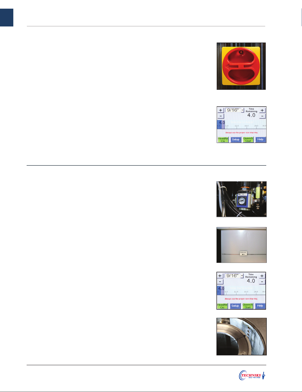
• Turn the power switch clockwise to turn on the machine. Wait as your
machine powers up and displays the input screen.
• Touch “Head Air On” to test the Air connection. “Head Air Off” to cancel.
• Touch the “Quench Start” button on the touch screen. The pedestal
should lower into the coolant well and return automatically.
• Verify coolant is flowing from the internal coolant nozzles, filling the
pedestal well.
• Your Quencher is now ready for use.
VERIFYING PROPER INSTALLATION (QUENCHER)
• Connect the machine to your power supply.
• Connect the source air line to the machine’s air inlet.
• Verify the gauge on the Air Pressure Regulator reads 90 psi.
• Carefully pour approximately 20 gallons of clean water into the Quench
tank through the pedestal hole.
• Fill tank up to Fluid Level line. Do not spill any water on the machine.
QUENCHER SETUP
VERIFYING PROPER INSTALLATION (SHRINKPRO)
• Turn the power switch clockwise to turn on the machine.
• Wait as your machine powers up and displays the input screen.
• Touch “Head Air On” to test the Air connection. “Head Air Off” to cancel.
• Your ShrinkPRO is now ready for use.
• The 00600-M ShrinkPRO requires a level, stable surface and good
ventilation for proper operation. Keep the machine clean and dry at all
times.
• Connect the machine to your power supply. The machine operates on
208V-480VAC on a 3-phase 30 amp circuit.
• Connect the source air line to the machine’s air inlet (90 psi required).
SHRINKPRO SETUP
6
Satisfaction guaranteed on all our CNC tooling solutions | www.techniksusa.com
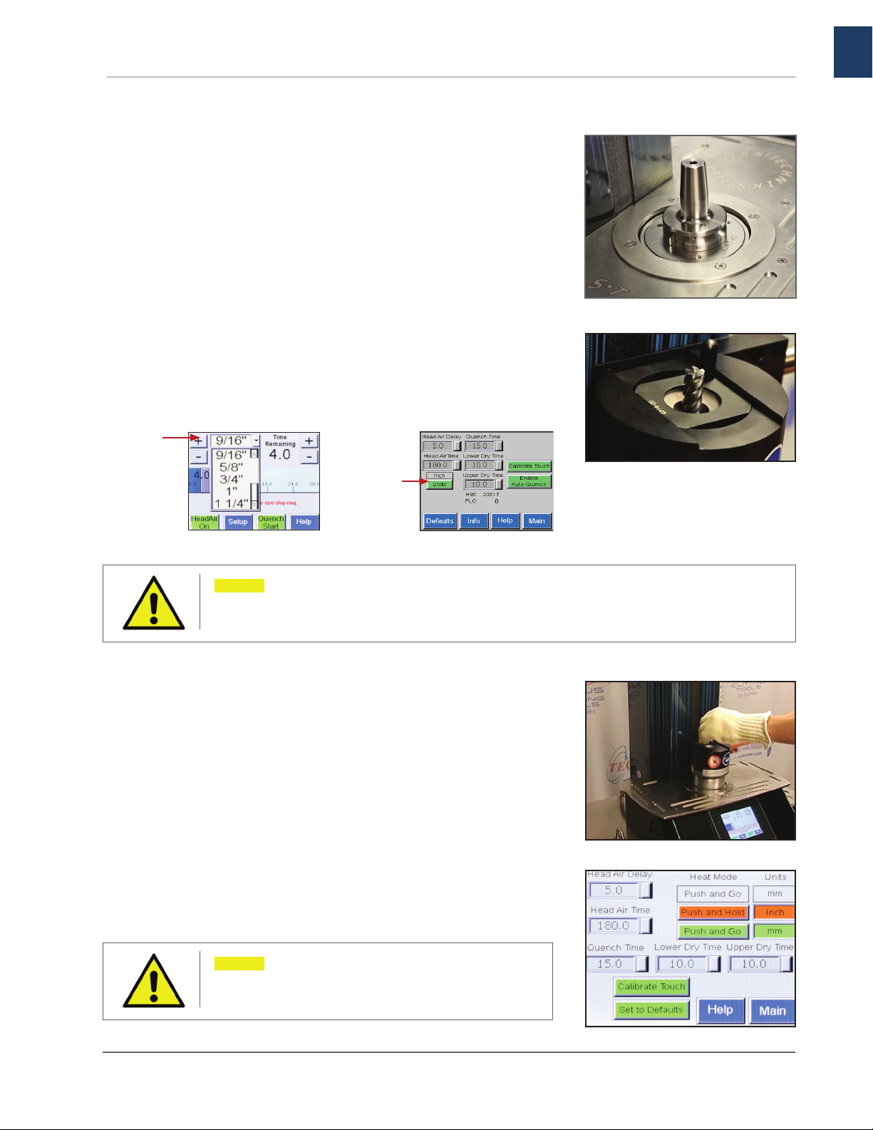
• Choose the toolholder seat that corresponds with your toolholder.
• Place the seat over the pedestal hole and insert your toolholder.
• Choose the induction stop ring that corresponds with your
toolholder.
• Place the stop ring into the induction head, rotate it 90˚ to secure
its position.
• Lower the induction head until there is an a 1/8” gap between the
stop ring and the end of the toolholder.
• From the main screen, select your tool shank size. You can switch
between inch or millimeter using the setup screen.
INSERTING YOUR CUTTING TOOL
• Heating duration is set by default based upon shank size. Use the
gray slider bar on the touch screen to add or subtract time.
• Wearing the insulated glove on one hand, with your other hand,
press and hold the red button located on the induction head.
• After 2–3 seconds attempt to insert the cutting tool into the
toolholder. Continue holding the button until the cutting tool is
successfully inserted into the toolholder. You can stop the heating
cycle at any time by releasing the red button.
HEATING CYCLE
Note: Never allow any part of the induction head
to contact the toolholder or cutting tool during
the heating cycle or damage to the machine may
occur.
REMINDER: Always inspect your cutting tool for any imperfections on the shank such as chips, burrs, or scarring. If you find any,
do not use that cutting tool in a shrink-fit toolholder, or it may no be able to remove it. The ability to insert and remove tools is
enhanced when cutting tools and holders are dry and clean.
REMINDER: If the heat cycle ends before the cutting tool can be inserted,
increase the duration by 10%. If the cutting tool is inserted before the
cycle ends, you may reduce the duration for that shank size.
Use the drop
down menu to
choose your
shank size
Touch units to
switch between
inches or metric
OPERATIONS GUIDE

7
EXTRACTING YOUR CUTTING TOOL
• The cooling cycle automatically begins 5 seconds after the heating
cycle ends. The cooling cycle automatically stops after 3 minutes.
• You can manually stop the cooling cycle after 30 seconds by
touching the “Head Air Off” button.
• Touch the“Head Air On” buttons to restart.
COOLING CYCLE (00600-M SHRINKPRO)
• Touch the “Quench Start” button to begin the 30 second cooling
cycle. The hot tool will be automatically lowered into the coolant
tank, the Head Air will automatically begin cooling the head.
• As the toolholder returns to the start position, high-pressure air
nozzles will remove excess moisture.
• Raise the induction head out of the way to make room to remove
the cutting tool.
COOLING CYCLE (00500-M QUENCHER)
Note: Always wear the insulated glove when
handling tools, even after the cooling cycle has
completed.
Note: Toolholders for smaller cutting tools
require less power to heat, but must be heated
to a higher temperature than larger tools to
perform insertion and extraction.
• Toolholders must be at room temperature before attempting
to extract the cutting tool. Place the toolholder / cutting tool
assembly into the seat and secure the stop ring into the induction
head. Lower the head until there is an 1/8” gap between the stop
ring and the end of the toolholder.
• From the main screen, select your tool shank size.
• Begin heating procedure: Wearing the insulated glove on one
hand, with the other hand, press and hold the red “Start” button
located on the induction head. Continue holding the “Start” button
throughout the heating cycle.
• Approximately 2-3 seconds before the heating cycle ends, attempt
to remove the tool from the toolholder with the gloved hand.
• The heating cycle will stop automatically at the end of the set
duration.
OPERATIONS GUIDE
REMINDER: If the tool cannot be extracted on the first try, cool the tool to
room temperature and increase the heating duration by 10% and try again.
8
Satisfaction guaranteed on all our CNC tooling solutions | www.techniksusa.com
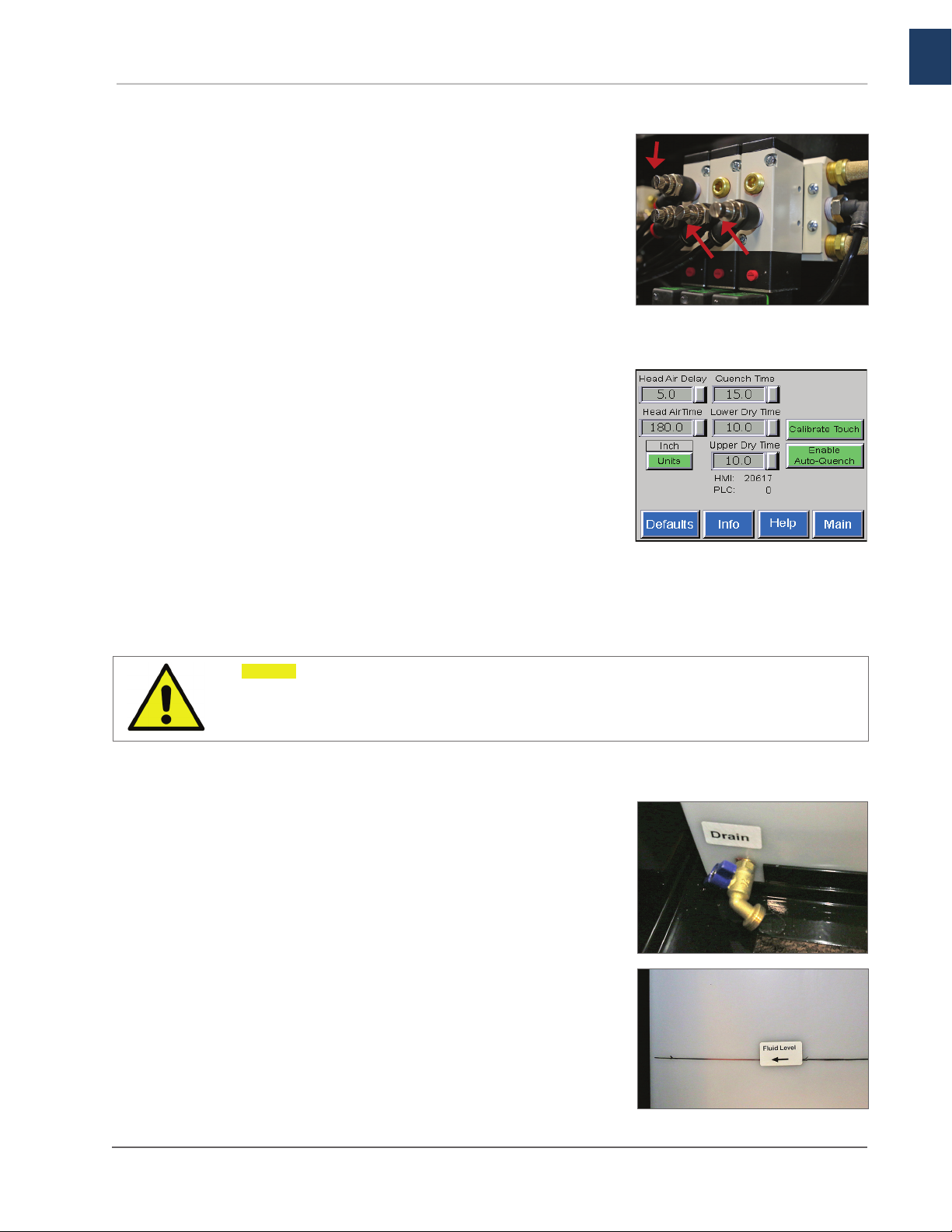
ADJUSTING COOLING TIME
• The descending speed of the toolholder is adjusted by the speed
flow control on Port B of the air valve.
• If the descending speed is set too slow, there may not be adequate
cooling time.
• On the Setup screen, adjust the “Quench Time” to account for poor
cooling due to a slow descending speed.
ADJUSTING DRYING TIME
• The ascending speed of the toolholder is adjusted by the speed
flow control on Port A of the air valve. If the ascending speed is
too high, there may not be adequate time for the toolholder to dry.
• On the Setup screen, adjust the “Lower Dry Time” so the lower dry
air valve shuts off after the pedestal passes the lower nozzles.
• Adjust the “Upper Dry Time” so the upper dry air valve shuts off
when the pedestal reaches the top position.
• If the coolant becomes contaminated it will need to be replaced.
• Begin by draining the coolant through the Coolant Drain Valve.
Then flush the Quench tank and close the drain valve. Be sure
to dispose of the contaminated coolant following the appropriate
environmental guidelines in the back of this manual.
• Remove, clean and replace the strainer from the pump inlet hose
in the tank.
• Add 1 gallon CIMTECH 310 (Techniks Part No. 00500-C) to 20
gallons fresh water. Refill the tank with clean approved coolant
and run a Quench cycle to verify coolant is flowing properly.
REMINDER: Always use the supplied insulated glove and exercise caution when handling toolholders. All personnel should be
clear of the machine before starting the tool change or Quench cycle. Never touch any toolholders that are not properly cooled.
The Quenching Time and coolant flow must be set to provide adequate cooling time to protect personnel from injury caused by
improperly cooled toolholders.
00500-M QUENCHER SYSTEM ADJUSTMENTS
A ports
B ports
IN CASE OF CONTAMINATED COOLANT
Note: The drying cycle is not meant to remove all
of the moisture from the toolholder. The drying
cycle should be adjusted to remove most of the
dripping coolant from the toolholder.

9
MSDS Sheets for CIMTEC Coolant

10
Satisfaction guaranteed on all our CNC tooling solutions | www.techniksusa.com
.
MSDS Sheets for CIMTEC Coolant

11
.
MSDS Sheets for CIMTEC Coolant

12
Satisfaction guaranteed on all our CNC tooling solutions | www.techniksusa.com
MSDS Sheets for CIMTEC Coolant

13
MSDS Sheets for CIMTEC Coolant

14
Satisfaction guaranteed on all our CNC tooling solutions | www.techniksusa.com
MSDS Sheets for CIMTEC Coolant

15
Satisfaction guaranteed on all our CNC tooling solutions | www.techniksusa.com

SHRINK-LOCKED tool holders are enhanced with our
patented TTG-594 compound for 6X the gripping force
of standard shrink fit holders.
WHY TRY SHRINK-LOCKED?
• Enjoy the peace of mind knowing your tool
will never slip, even in the most aggressive
applications.
• Run harder – higher speeds and feeds.
• Never spin or pull out a cutting tool..
• No modification to your tool shank required.
• No impact to accuracy or tool changes.
• Locked drive on standard carbide round shanks
.
IT’S NOT JUST SHRINK-FIT,
IT’S SHRINK-LOCKED!
Techniks Inc. 9930 E. 56th St. Indianapolis, IN 46236 | 800.597.3921 | www.techniksusa.com | [email protected]
Techniks is a proud member of Techniks Tool Group. Connect with Techniks Tool Group
Proprietary TTG-594 compound is embedded
in the I.D. bore of the holder, creating millions
of microscopic teeth adding bite to the
cutting tool/tool holder connection.
Unleash the full power of your CNC
machine and cutting tool with the
strongest shrink-fit connection.
This manual suits for next models
3
Table of contents
Other Techniks Industrial Equipment manuals


Popular Industrial Equipment manuals by other brands

Haufftechnik
Haufftechnik HRD150 SGi x b60 installation instructions

Pulsar
Pulsar 7/20/SATEL/PUSTA instructions

COREMO OCMEA
COREMO OCMEA A3-3N User and maintenance manual

SCHUNK
SCHUNK KSC-D 125 Installation and operating instruction

FlexArm
FlexArm GH-24 Installation & operation manual

Ecolab
Ecolab VANGUARD WASH MAX Installation and operation manual


