Ecolab VANGUARD WASH MAX User manual
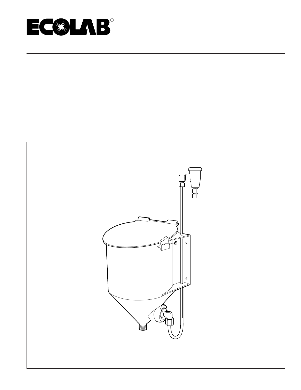
VANGUARD®WASH MAX
Installation and Operation Manual
22937/0404/0602 Copyright Ecolab Inc. 2001 9237-2457
Institutional Division
Ecolab Center
St. Paul, MN 55102
R

This page intended
to be blank.

iii
TABLE OF CONTENTS
VANGUARD®WASH MAX
Installation and Operation Manual
Section...
1.0 PREFACE........................................................................................................ 1
2.0 INTRODUCTION.............................................................................................. 1
2.1 Principle of Operation.............................................................................. 1
3.0 SPECIFICATIONS........................................................................................... 2
3.1 Dimensions.............................................................................................. 2
3.2 Plumbing Requirements .......................................................................... 2
3.3 Electrical Requirements .......................................................................... 2
3.4 Components Not Supplied ...................................................................... 2
4.0 INSTALLATION PROCEDURES .................................................................... 3
4.1 Machine Mounting the Reservoir............................................................. 3
4.2 Wall Mounting the Reservoir ................................................................... 3
4.3 Initial Electrical Connections ................................................................... 3
4.4 Install Wash Tank Connector and Tubing ............................................... 3
4.5 Determining the Reservoir Water Supply ................................................ 4
4.6 Plumbing into the Water Supply.............................................................. 4
4.7 Start-up Procedures ................................................................................ 4
4.8 Guardian ................................................................................................. 4
4.9 Power Activator ....................................................................................... 5
4.10 Electronic Overshoot Control Board Adjustment..................................... 5
4.11 Timer Setting Procedures........................................................................ 5
5.0 TROUBLESHOOTING..................................................................................... 6
5.1 Inadequate Water To/From Reservoir Into Dishmachine ........................ 7
5.2 Low Product (effluent) Concentration Causing False Alarm.................... 7
5.3 Power to Solenoid Valve - No water Feed to Reservoir .......................... 7
5.4 Excessive Overshoot (POWER ACTIVATOR only)................................. 7

This page intended
to be blank.

1
1.0 PREFACE
Thismanualhasbeenwrittentopresentthebasicinstallation
and operational characteristics of the VANGUARD Wash
Max.
Thismanualapplies,initsentirety,tocurrentunits.
Guidelines will be suggested in reference to the preferred
methodofinstallation,however,thevarietyofequipmentand
the surrounding physical environment will dictate the actual
installation of the VANGUARD Wash Max
WARNING - These installation and servicing in-
structions are for use by qualified personnel only.
The installation must be made in accordance with
local plumbing and electrical codes.
The VANGUARD Wash Max Reservoir is a system de-
signedtoconvertsolidorpowderedwarewashingdetergent
into a high strength liquid for dispensing into the wash tank
of a dishmachine. The system consists of a reservoir,
possiblyaGuardianKitoraPowerActivatorKitandisused
in conjunction with the VANGUARD EcoCenter, Control
Max,VANGUARD2026,Senso-Matic26electroniccontrol,
or the Centron.
TheVANGUARDWashMaxReservoir consists of aheavy
duty reservoir for holding a solid detergent or powder, a
vacuum breaker, tubing, an empty capsule light, a cover
safetyswitchandaspraynozzlelocatedatthebottomofthe
reservoir.The reservoirwill holdonecapsuleofsoliddeter-
gent or up to 6 pounds of powdered detergent.
2.1 Principle of Operation
The basic principle of operation of the VANGUARD Wash
Max Reservoir is that it converts solid or powdered
warewashing detergent into an extremely high strength
liquid and directs this liquid into the wash tank of a
dishmachine.Product capsulesorpowderareaddedtothe
dispensersupply compartmentbyliftingthelidofthereser-
voir and inserting the capsule or pouring the powder.
Asolenoidvalve,activatedbytheconcentrationcontrolunit,
allows water to flow through the vacuum breaker to the
spray nozzle. The nozzle is designed to apply a uniform
spray pattern to the product surface. The solid detergent
dissolves and flows, by gravity, into the dishmachine wash
tank.
When the conductivity sensor in the wash tank senses the
needformoreproduct,theVANGUARDEcoCenter,Control
Max,VANGUARD2026,Senso-Matic26orCentronModel
526 opens the 24 volt AC solenoid valve allowing water to
flow to the VANGUARD Wash Max Reservoir through the
vacuum breaker to the spray nozzle. The nozzle is de-
signed, to apply a uniform spray pattern to the product
surface.Thesoliddetergentdissolvesandflows,bygravity,
throughtubingintothewashtankofthedishmachine.When
the conductivity sensor in the wash tank senses an ad-
equate detergent strength, the VANGUARD EcoCenter,
ControlMax,VANGUARD2026,Senso-Matic26orCentron
Model 526 closes the solenoid valve.
2.0 INTRODUCTION
2
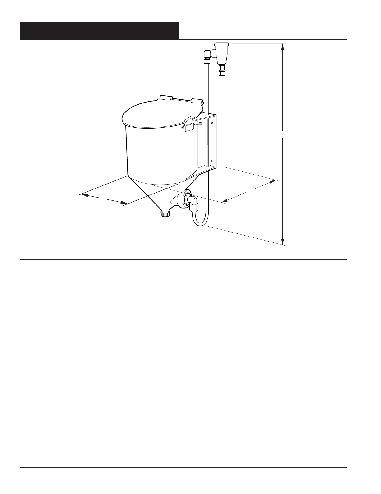
WD
H
3.0 SPECIFICATIONS
Component Diagram
3.1 Dimensions
• Height: 21" (53.3 cm)
• Width: 10-1/2" (26.7 cm)
• Depth: 8-1/2" (21.6 cm)
This reservoir may be wall mounted or machine mounted.
Allow appropriate space, about 8" (20.3 cm), above the
reservoir for opening the cover as well as for the vacuum
breaker assembly.
3.2 Plumbing Requirements
A source of 120°F (48.9° C) to 150°F (65.5° C) water at a
minimum of 12 psi (.844 kgm/cm2) and 1 gallon per minute
(.063 liters/sec.) flow rate are required for the VANGUARD
Wash Max Reservoir.
Mayon tubing, 5/8" I.D. (15.9 mm), is required to direct the
effluent from the reservoir to the wash tank.
3.3 Electrical Requirements
The VANGUARD Wash Max Reservoir is supplied with a
20' (6 meter) length of 2 conductor cable. The conductors
are connected to the safety switch on the reservoir.
3.4 Components Not Supplied
• 5/8" I.D. (15.9mm) Mayon tubing
• 1/4" O.D. (6.4mm) copper tubbing
• Wall anchors (standard wall anchors or toggle bolts)
• Special mounting bracket (if required)
NOTE: Included in the VANGUARD Wash Max Reser-
voir package will be components common to both the
GUARDIAN and the Power Activator (vacuum breaker,
hose and assembly, hose clamps, needle valve, etc.).
To adapt the reservoir for a GUARDIAN product or
SOLID POWER product, one of the following must be
ordered.
1. GUARDIAN KIT
a. GUARDIAN Screen
b. Retaining Ring
c. GUARDIAN Safety Label and Nameplate
d. GUARDIAN Wall Chart
2. POWER ACTIVATOR KIT
a. Safety Grate
b. POWER ACTIVATOR Nameplate
c. POWER ACTIVATOR Wall Chart
d. Instructions - Conversion GUARDIAN to
POWER ACTIVATOR
3
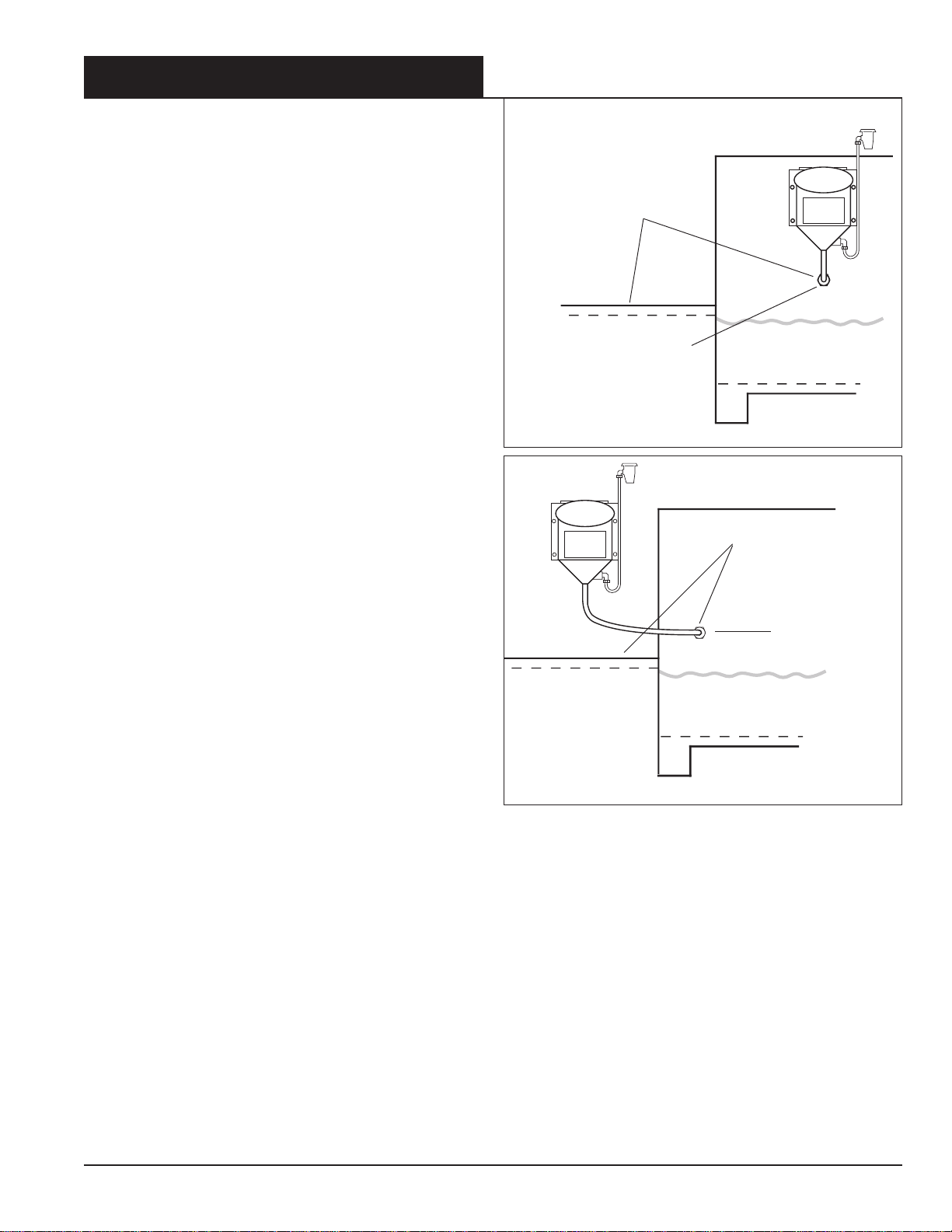
Figure 4-1
Figure 4-2
4.0 INSTALLATION PROCEDURES
NOTE:RefertotheappropriateVANGUARDEcoCenter,
Control Max, VANGUARD 2026, Senso-Matic 26 or
Centron Model 526 I/O Manual for installation instruc-
tions of the control unit, conductivity cell and the
solenoid valve hook-up.
Theinstallationofthe VANGUARD Wash MaxReservoiris
essentially the same whether machine mounted or wall
mounted.
4.1 Machine Mounting the Reservoir
1. The reservoir must be mounted at a height below eye
level,buthigh enoughtoensurea downhillslopeof the
detergentdischargetubefromthereservoirtothewash
tank inlet connector.
Refer to Figure 4-1.
2. Mount the reservoir unit to the dishmachine wash sec-
tion. To prevent crimping of the discharge tubing, the
bottom two (2) mounting holes should be located at
leasteleven(11)inches(27.9cm)abovethewashtank
inlet connector. Use the mounting template to ensure
proper location of the holes. Use the four (4) bolts and
nuts supplied with the kit to secure the reservoir to the
dishmachine wall.
Refer to Figure 4-1.
NOTE: The shortest possible outlet tube run, be-
tween the bottom of the reservoir and the inlet
connector, is required. The outlet tube should not
have any dips in it.
4.2 Wall Mounting the Reservoir
1. Be sure to mount the dispenser at a height below eye
level and use the mounting template to mark four (4)
mounting hole positions. Secure the unit to the wall
usingappropriatewallanchors and/or toggle bolts.Itis
essentialthattheVANGUARDWashMaxReservoirbe
fastened firmly as the weight of the capsule being
placedinto
thereservoirrequiressufficientsupport.
Referto
Figure 4-2.
4.3 Initial Electrical Connections
1. TheVANGUARDWashMaxReservoirissuppliedwith
a 25' (7.6 meters) 2 conductor wire. The RED and
BLACK wires will be used to wire to the designated
safety switch wiring in the dispenser controller. These
should be connected as illustrated in the controller
wiring diagram.
4.4 Install Wash Tank Connector and Tubing
1. ToInstallthewashtankconnectorandtubing,locatethe
wash tank connector above normal water level in the
wash tank. Position the connector in a manner, such
that the effluent from the reservoir will not directly
contacttherackorutensils in the dishmachine,
referto
Figure 4-1.
NOTE: Ensure a continuous downhill flow of deter-
gent from the reservoir Into the wash tank
SOLUTION SUPPLY MUST BE
ABOVE FLOOD STAGE
(OVERFLOW RIM)
OVERFLOW RIM
OVERFLOW RIM
SOLUTION SUPPLY
MUST BE ABOVE
FLOOD STAGE
(OVERFLOW RIM)
WASH TANK
CONNECTOR
WASH TANK
CONNECTOR
2. Cut a 7/8" hole in the wash tank wall and install the
connector with the locknut and gaskets supplied.
NOTE: While drilling, it is recommended to catch
the shavings with a rag.
3. Cut and install the 5/8" I.D. (15.9mm) Mayon tubing
betweenthereservoirproductoutletandthewashtank
connector. Secure the tubing with clamps supplied in
the kit.
NOTE: Do not crimp the tubing.

4
Wash Max
Figure 4-3
4.5 Determining the Reservoir Water Supply
The hot water supply for the VANGUARD Wash Max
Reservoir should fall within the range 120° F (48.9°C) to
150°F(65.5°C.).Itmustbe a minimum of 12psi(.844kgm/
cm2) flow pressure with a minimum of 1 gallon per minute
(.063 liter/sec.) water flow.
1. Select the point for connection to the water supply so
that there is a minimum distance between the water
sourceandthereservoir.Ifthisdistanceislessthan15'
(4.6 meters) and a minimum of 12 pounds (.844 kgm/
cm2)flowpressureisavailable,1/4"O.D.coppertubing
is recommended,
refer to Figure 4-3.
If this distance is greater than 15' (4.6 meters) and/or
less than 12 pounds flow pressure (.844 kgm/cm2),
3/8"coppertubingisrecommendedforoptimumperfor-
mance.
NOTE: DO NOT USE 180°F WATER SOURCE.
4.6 Plumbing into the Water Supply
1. Shut off water supply. Tap into the water source and
installtheneedlevalvesuppliedwiththereservoir,
refer
to Figure 4-3.
The needle valve provides a means to regulate water
flow to the dispenser and it permits servicing the sole-
noid valve without the need to shut off the main water
supply.
2. Installcoppertubingbetweentheneedle valve and the
solenoidvalveatbottomofdetergentcontrollercabinet.
3. Install a length of copper tubing between the solenoid
valve and the vacuum breaker on the VANGUARD
Wash Max Reservoir.
4.7 Start-up Procedures
1. Adjust the VANGUARD EcoCenter, Control Max or
VANGUARD 2026 for proper detergent concentration.
Refer to the respective I/O Manual for instructions.
2. Fill the dishmachine with fresh water and turn on the
dishmachine with no detergent in the reservoir. The
controller will call for feed.
3. Check for water leaks and proper safety switch opera-
tion by lifting cover - the water flow should stop.
NOTE: Refer to Sections 4.8 - 4.11 only if you are using
the Guardian or Power Activator dispensers.
4.8 Guardian
InsuretheGUARDIANnameplateandsafetylabelisneatly
and firmly attached to the front side of the reservoir. The
surfacemustbecleanforpermanentattachment.Attachthe
GUARDIAN wall chart where it can easily be seen by the
dishmachine operators.
When the reservoir is used with a powdered GUARDIAN
detergent,thelargefinemeshGUARDIANscreenmust be
DETERGENT
CONTROLLER
SOLENOID VALVE
HOT WATER
SOURCE
NEEDLE
VALVE
TO WASH
TANK
Figure 4-4
inserted into the reservoir (before adding product). The
screenisinstalledwiththesmallknobatthecentertopofthe
screen facing up. The screen retainer ring is next inserted,
snugagainsttheouterrimofthescreen(withtheprongsup).
This retainer ring is to hold the screen firmly in place,
refer
to Figure 4-4.
Up to 6 pounds (2.7 kg) of GUARDIAN detergent can now
be added to the GUARDIAN reservoir.
NOTE:Alwayswet anewscreenbeforeaddingproduct
to avoid potential powder sift through.
AdjusttheSenso-matic26 forproperdetergentconcentra-
tion.RefertoSenso-Matic26I/OManual(#6435)fordetails.
GUARDIAN
SCREEN
RETAINER
RING
POWER
ACTIVATOR
GRATE

5
4.9 Power Activator
InsurethePowerActivatorlabelisneatlyandfirmlyattached
tothefrontside of thereservoir.Thesurfacemust be clean
forpermanentattachment.DisplaythePowerActivatorwall
chart where it can easily be seen by the dishmachine
operators.
The Power Activator reservoir is for use with the solid
capsule detergents (i.e. SOLID POWER or EXCALIBER).
Thesmallgratewiththelargemeshmustbeinsertedintothe
bottom of the reservoir. This grate is to keep any large
particles that may drop from the capsule and clog the tube,
refer to Figure 4-4
.
4.10 Electronic Overshoot Control Board
Adjustment
Thefollowingrecommendedtimersettingsaregeneraland
"fine tuning" of the Overshoot Control Board must be done
attheaccounttodealwiththespecificconditions(i.e.,water
temperature, pressure etc.) Follow procedures below:
Recommended Timer Settings
MACHINE ON OFF TOTAL PERCENT
TYPE TIME TIME TIME FEED
Door Type 2.5 sec. 7.5 sec. 10 sec. 25%
Conveyor/ 4 sec. 11 sec. 15 sec. 25%
Flight
Setting 9:00 11:30
On Timer -9:30 -12:30
4.11 Timer Setting Procedures
1. The left timer pot controls the "on" time and the right
timer pot controls the "off" time. The "on" time is when
theunitactuallyfeedsdetergent,andthe"off"timeisthe
pause while dissolved detergent solution drains into
and disperses within the wash tank. The "on" timer is
always energized first and is identified by the red LED
lightbeingilluminated.Thislightisnotonduringthe"off"
time.
The "on" - "off" cycle repeats itself during the time the
Senso-Matic 26 is calling for feed.
2. Fill the dishmachine with fresh water and turn on the
dishmachine with no detergent in the reservoir. The
S-26 will call for feed. Adjust the timers.
3. Refer to the above chart for approximate time settings.
Adjust the left timer for "on" time and the right timer for
"off" time. These times can be easily measured by
observing the red LED light on the Overshoot Control
Board. As the S-26 is calling for feed, the red light will
pulseon andoff.Timetheseandcomparetotheabove
chart.
NOTE: Rotate timers clockwise to increase time
and counterclockwise to decrease time.
Figure 4-5
Figure 4-7
Figure 4-6
GUARDIAN
SENSO-MATIC 26
TO SAFETY SWITCH
POWER ACTIVATOR
SENSO-MATIC 26 WITH OVERSHOOT CONTROL
EXCEPT CENTRON
POWER ACTIVATOR
SENSO-MATIC 26 OVERSHOOT CONTROL
IN CENTRON*
*CONNECT TO POWER ACTIVATOR PER CENTRON
MODEL 526 I/O MANUAL

6
5.0 TROUBLESHOOTING
The following Troubleshooting procedures are specific to the VANGUARD Wash Max Reservoir System. These
proceduresassumethattheVANGUARDEcoCenter,ControlMaxorVANGUARD2026arefullyoperational-ifnecessary
to troubleshoot these components, refer to the VANGUARD EcoCenter, Control Max or VANGUARD 2026 I/O Manuals.
Symptom Action
5.1 Inadequate Water To/From Reservoir Into
Dishmachine
ObservewhetherornoteffluentisflowingfromtheRESER-
VOIR into the dishmachine while controller is in “feed”
condition. Water volume should be a minimum of 1 GPM.
1. If there is no (or very little) effluent flow:
a. CheckandinsureRESERVOIRcoveriscompletely
closed (safety switch closes when cover is at cor-
rect angle).
b. Check to insure all shut-off valves (and needle
valve) at the water source are fully open.
c. Checkfor24voltsatthesolenoidvalvecoil.Ifno24
volts,refertoStepC-NOPOWERTOSOLENOID.
If24volts,checktomakesurethevalveisopening.
If it is not opening, it is defective and must be
replaced.
d. Check for clogging in the water line, the solenoid
valve/line strainer, and the vacuum breaker (i.e.,
loosen compression fittings to check for water).
e. Check for broken or plugged spray nozzle. Check
for blocked or crimped product outlet (Mayon) tub-
ing.
2. Ifthereiseffluentflowbutlessthan1gpm,checkfor12
psi (.844 kgm/ cm2) minimum water pressure at outlet
side of vacuum breaker: use the Guardian Pressure
Tester (fitting with pressure gauge P/N 9270-1O77). If
pressure is less than 12 psi (.844 kgm/cm2):
a. Check to insure no kinks in water feed tube, mini-
mum bends and length of feed tube, and for pos-
sible clogging of shut-off/needle valve, solenoid
valve, etc. as described above. Check pressure
reducing valve if present.
b. Iflowwaterpressurepersists,convertthe1/4"(6.3
mm)waterfeedtubeto3/8"(9.5mm)tubing(Guard-
ian Low Pressure Kit, P/N 9237-6003). This will
correct or help most low water pressure problems.

7
Symptom Action
5.2 Low Product (effluent) Concentration Causing
False Alarm
If the alarm repeatedly goes off with product still In the
reservoir(presumingdelaytime is properlyadjusted)prod-
uctisnot beingdissolved.Effluentconcentration shouldbe
a minimum of 5O drops (Titrate 5 - Indicator P) for “solid”
Power Activator detergents.
1. If concentration of effluent is low:
a. Checkforlowwatervolumeandlowwaterpressure
(see 1 and 2 on page 5).
b. Check to insure cap is removed from detergent
“capsule.
c. Check for misaligned, partially plugged or broken
spray nozzle.
d. Checkforwatertemperaturebeingtoocold(solubil-
ityisgreatlydecreasedattemperaturesbelow120°
F (48.9° C).
2. Ifeffluentconcentrationisstillinadequate(after check-
ing1a-e)installalternate5.6nozzletoincreaseeffluent
concentration(SprayNozzleP/N8531-2213).Ifeffluent
concentrationischeckedtobeokayandfalseorprema-
ture empty capsule alarm still occurs:
a. Check to insure delay time is set long enough (do
not exceed cycle time on timed cycle machines,
including D-Energizer controlled machines).
1. Check for water supply to solenoid valve. If no water to
valve, check:
a. Needle valve open and water coming from it.
b. Makesuretubingisnotpluggedorcrimpedandthat
there is water at the solenoid valve.
2. Checkforwaterfromsolenoidvalvewithcontrollerina
feed condition. If no water check for:
a. Defectivevalvecoil,plunger,spring,ordiaphragm.
b. Plugged line strainer in solenoid valve. If there is
water through the solenoid valve, check:
c. Crimped or plugged tubing to reservoir, defective
vacuum breaker or plugged spray nozzle.
If there is excessive overshoot titration in the wash tank,
makenecessaryadjustmentstotheovershootcontrolboard
reducingthepercentageof"on"time.Ifadjustments do not
alterthepulsedfeedtime/rate,replacetheOvershootCon-
trol board. If there is a pulsed feed but overshoot is exces-
sive and cannot be controlled, reduce feed water tempera-
ture.
5.3 Power to Solenoid Valve - No water Feed to
Reservoir
5.4 Excessive Overshoot (POWER ACTIVATOR
only)
Table of contents
Other Ecolab Industrial Equipment manuals

Ecolab
Ecolab DG1-III-DLA-PCB User manual

Ecolab
Ecolab Chameleon PLUS BW3 User manual

Ecolab
Ecolab Inspexx SD - Mrk. II Manual

Ecolab
Ecolab Booster 6 User manual

Ecolab
Ecolab ECO User manual

Ecolab
Ecolab Hybrid 7 BF4 Manual

Ecolab
Ecolab Lubo-DryExx -Basic User manual

Ecolab
Ecolab FoamGuard Airomatic Manual

Ecolab
Ecolab Connexx Basic Quick start guide

Ecolab
Ecolab BFE3 User manual
Popular Industrial Equipment manuals by other brands


All Power Labs
All Power Labs PP30 Operation manual

Fitel
Fitel S327 operating instructions

Tsubaki
Tsubaki ECHT-FLEX COUPLING NES Series installation manual

Hunter
Hunter AutoComp Elite operation instruction

Rothenberger
Rothenberger ROWELD P160-630B/Plus Instructions for use

GRUP ARGE
GRUP ARGE KSK 10 user manual