Techniks 00450-M User manual
www.techniksusa.com
00450-M SHRINKSTATION
OPERATIONS MANUAL
COMPLETE INSTALLATION AND TROUBLESHOOTING GUIDE
Techniks Inc. 9930 E. 56th St. Indianapolis, IN 46236 | 800.597.3921 | www.techniksusa.com | [email protected]
Techniks is a proud member of Techniks Tool Group. Connect with Techniks Tool Group
1
Phone: (800) 597-3921 or (317) 803-8000 • Fax: (317) 803-8001
The Model 00450-M has been constructed using the latest technology and are extremely safe and easy to
operate. Despite that, there is still some danger if these units are operated incorrectly and/or by untrained
personnel.
Pay particular attention to the following Cautions and Warnings marked with the “Attention” and “Danger”
symbols. Failure to follow safe operating practices may cause injuries, death, or damage to the machine,
and may void your manufacturers’ warranties.
• Before attempting to use the unit you must have
read and fully understood this Owners Manual. Keep
this Owners Manual within easy reach of operating
personnel.
• Visually inspect the unit, power cord, and accessory
items for any signs of wear or damage before
operating the unit. Do not use the unit if there is
any sign of damage, or if the unit is not performing
normally.
• Never operate the machine without the correct
induction stop ring in place on the induction head. Do
not allow any part of the induction head to contact
the toolholder or cutting tool during operation or
damage to the machine may occur.
• Do not wear rings, bracelets, or other metallic objects
while operating the machine. Metallic objects may
heat up very quickly when near the induction head
during operation.
• Use the provided thermal insulated glove whenever
handling tools or toolholders. Never try to handle
hot tools or toolholders until the cooling cycle is
complete.
• If the machine is moved from a cold environment
to a warm one, wait two hours before operating
to prevent condensation build-up from causing
electronic system errors.
• Persons with heart pacemakers may not operate
the machine, and must maintain a minimum safe
distance of 6 feet (2 meters) from the machine at all
times.
• Cutting tools have sharp edges. Handle with caution.
• Operating the unit while improperly connected or at
the wrong voltage may damage the unit and could
possibly cause death or injury.
• Position the power cord so it cannot be damaged by
fork trucks or other equipment, or cause a tripping
hazard for personnel.
• Do not operate the machine in a wet environment
where exposure to coolant or spills are likely to
occur. Electric shocks or damage to the machine
may occur.
• Never operate the machine around flammable
materials, or fumes. Do not use flammable liquids
or aerosols to clean tool holders. Never expose the
machine or hot tools to combustible materials.
• Never open the machine or attempt repairs or you
will VOID the manufacturer’s warranty. Dangerous
residual voltage is inside that may cause death or
injury.
• Unauthorized modifications or changes to
the ShrinkSTATION machine will VOID your
manufacturer’s warranty. Do not try and service your
unit yourself. Techniks can provide any necessary
repairs or maintenance. Do not modify or disable the
built-in safety features of the machine.
• Turn off the power switch and disconnect the power
cord from the outlet before cleaning, servicing, or
storing the unit.
• Do not operate this machine, if the EOT switches are
not working properly.
Make sure you read, understand and follow these Cautions and Warnings, as well as the complete technical notes,
setup and operation instructions before installing and using your machine.
IMPORTANT - CAUTIONS & WARNINGS

2
Satisfaction guaranteed on all our CNC tooling solutions | www.techniksusa.com
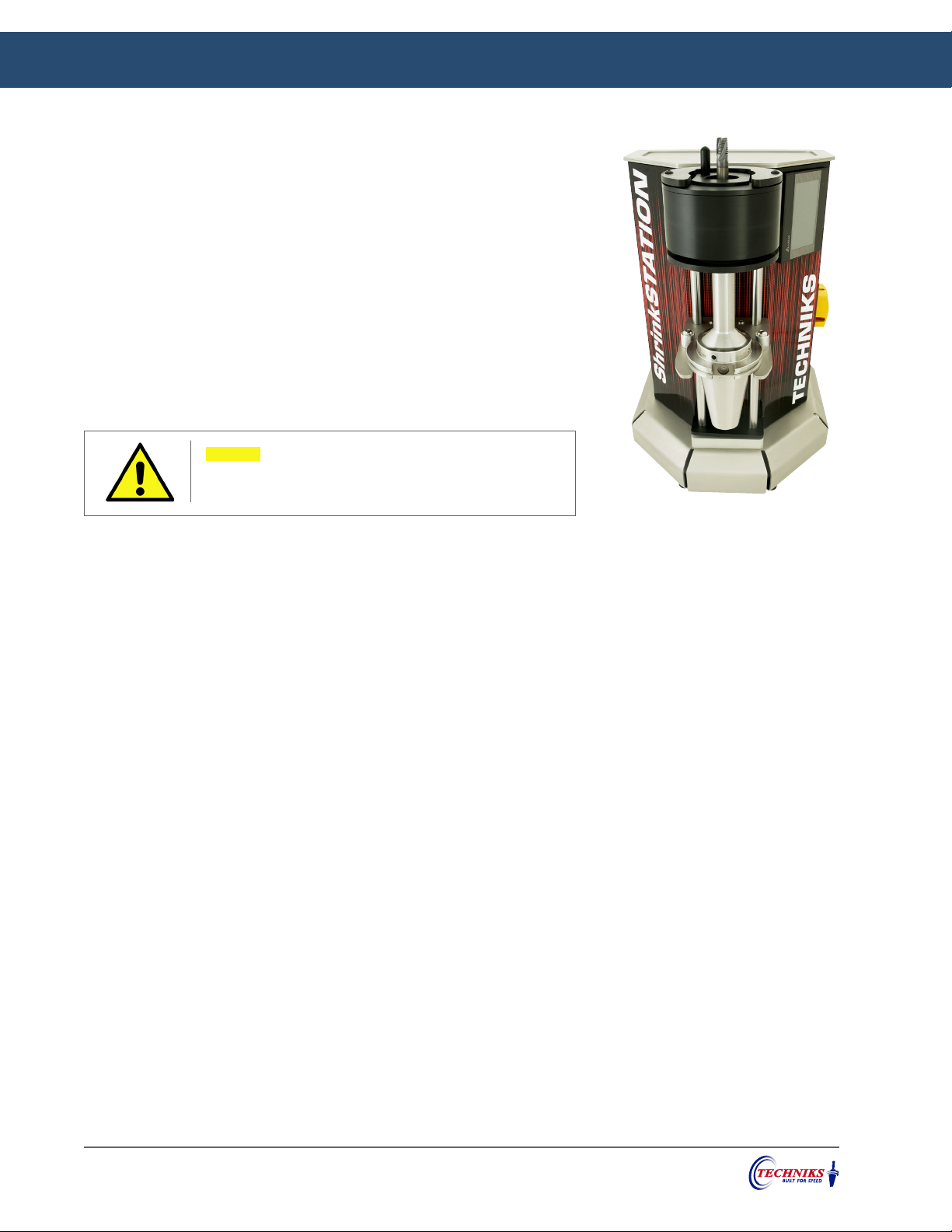
IMPORTANT – TECHNICAL NOTES
POWER REQUIREMENTS & HEATING SPEEDS
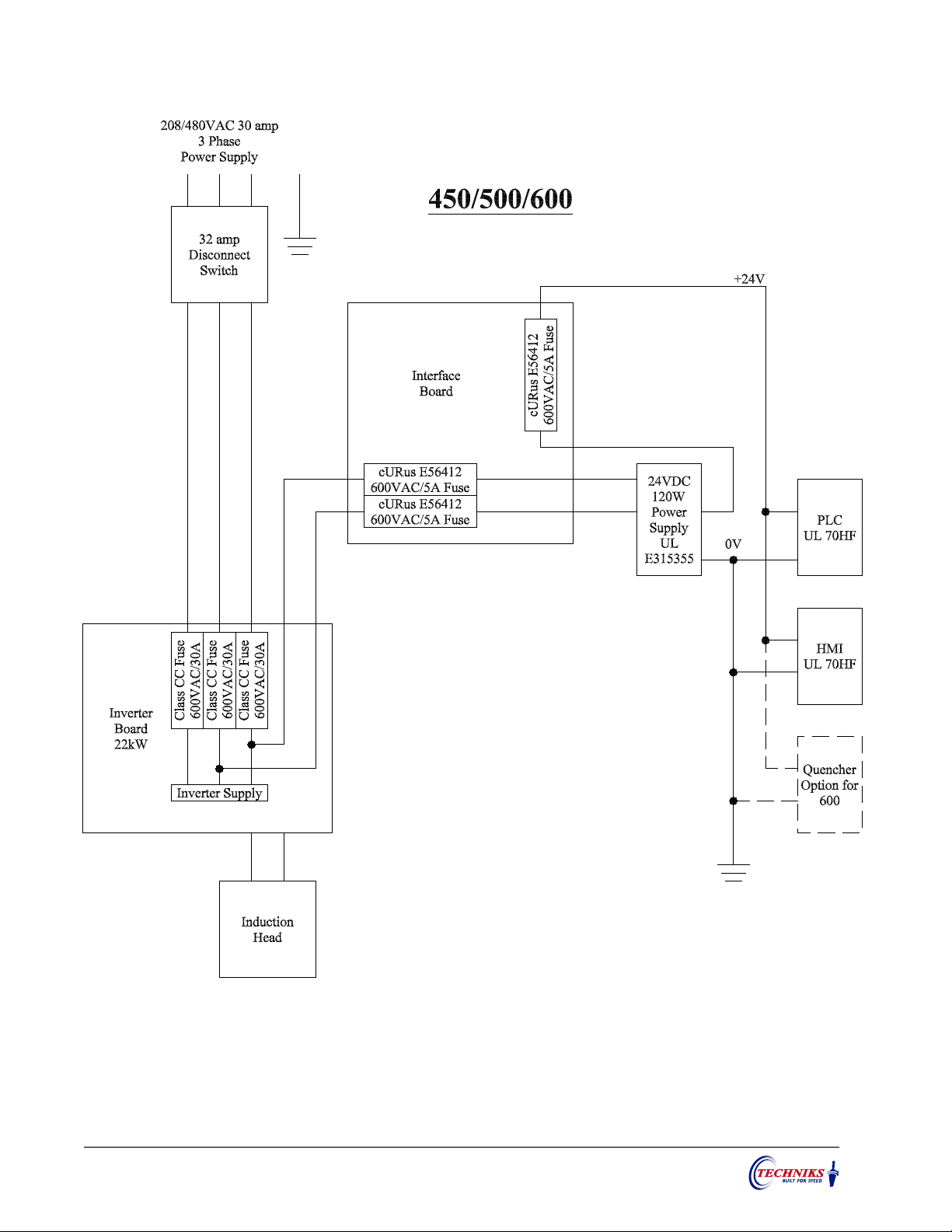
Techniks Model 00450-M operates on 208-480 VAC, 30amp supply. Tool holders for smaller cutting tools
require less power to heat, but must be heated to a higher temperature than larger tools to perform
insertion and extraction.
NOTE: Do not activate the heat controls without a toolholder in position.
AUDIBLE FEEDBACK
During operation, ShrinkSTATION machines power source generates an audible feedback tone that
changes frequency depending on the tool holder size and temperature. It is not unusual to hear a pitch
change as the tool holder temperature increases. Do not be alarmed if you hear this tone as it is normal.
If you are heating a large tool holder, it is unlikely that you will be able to hear the tone generated at all.
SHRINKFIT TOOLHOLDERS
Techniks ShrinkSTATION machines make it easy and safe to perform shrink fit tool changes without
causing damage to the toolholder or cutting tool, as long as the machine is correctly installed and proper
operating procedures are followed. ShrinkSTATION machines are designed to work best with Techniks
shrink fit tool holders made from H13 tool steel with bore diameters from 1/8” to 1-1/4” (3mm to 32mm).
They are designed for shrink fitting tools with carbide shanks. Tool shank diameter tolerance is critical. At
least an H6 tolerance is advised for optimum performance.
Make sure toolholders are clean and free from defects before inserting the tool in the tool holder. If debris
or a burr is inserted into the tool holder with the tool, tool life may be reduced. Damage to the tool or
toolholder may also occur as the tool may be difficult or impossible to extract.
NOTE: Holders must be at room temperature before attempting to extract the cutting tool.
CUTTING TOOLS
Cutting tool shanks must be perfectly clean and free from burrs, scoring, or any damage. Any imperfections
in the shank can cause the cutting tool to lodge permanently in the toolholder. Burnished shanks can slip
in Shrink Fit holders under some conditions. Sand blasting the cutter shanks has improved the holding
power.
Techniks ShrinkFIT holders are made of H13 tool steel, tempered at 1050˚F. Heating a tool holder to or
above temper point will permanently damage the holding power of the tool holder. Never use an alternate
heat source on shrink fit toolholders or damage to the toolholder and cutting tool may occur.

3
Phone: (800) 597-3921 or (317) 803-8000 • Fax: (317) 803-8001
00450-M PARTS IDENTIFICATION & MACHINE REQUIREMENTS
FEATURES
• Output power of 22 kw
• Change 1/8" - 1-1/4" shanks in seconds
• Automatic cooling cycle by compressed air
Part No. Description Tool Change Rating L x D x H Ship Wt.
00450-M ShrinkSTATION 6-8 sec. 208-480VAC 30A, 3 phase 16"x 16"x 22" 70 lbs
PRODUCT SPECS
The ShrinkSTATION is an ideal solution for job shops or manufacturing facilities that
need a reliable shrink fit machine that can handle practically all sizes and types of
toolholders, and is affordable.
Every component of this machine from the industrial touch-screen interface, to the
motor driven transport rail, and the heavy-duty stainless steel base, is designed for
reliable performance and ease-of-use in demanding environments.
The ShrinkSTATION includes everything you need to perform shrink fit tool changes on
CAT40, CAT50, BT40, 63 and 100, C6 toolholders with gauge lengths up to 11” (280mm).
Other sizes available on request.
NEMA L16-30P plug comes installed on the power cord.
Requires a NEMA L16-30R receptacle.
TOUCH SCREEN CAPABILITIES
Jog Speed – The speed of the tool holder during manual movement.
Drop Distance – The distance the tool holder travels to provide the
optimum gap between the tool holder and the induction ring.
Auto Down Distance – The distance the tool holder travels to travel
away from the induction head for easy removal of the tool holder.
Lower EOT – The “Lower End Of Travel” switch inhibits the tool
holder movement away from the induction head, when the switch
is not activated.
Upper EOT – The “Upper End Of Travel” switch inhibits the tool
holder movement toward the induction head. If the induction ring
is not in place, the switch should not be activated.
Reminder: This machine heats the cutting tool and toolholder assembly. All personnel should be clear of the machine before
starting a tool change cycle. Wear the provided insulated glove to prevent accidental burns. Any glove used when operating this
machine should be rated at 500°F (260°C) or higher.
Part No. Description
00165 Induction Ring (3 - 5mm shanks)
00166 Induction Ring (6 - 12mm shanks)
00167 Induction Ring (14 - 20mm shanks)
00168 Induction Ring (25 - 32mm shanks)
385-20277-1 Tool Holder Adapter – CAT 50
385-20277-2 Tool Holder Adapter – HSK 63
385-20277-3 Tool Holder Adapter – CAT/BT 40
26139-L Thermal Insulated Glove
EACH SHRINKSTATION INCLUDES:
ADDITIONAL OPTIONS AVAILABLE:
450 Part Number Spindle Hole Diameter
385-20277-4 HSK 50 1.51"
385-20277-5 ISO/BT 30 1.26"
385-20277-6 HSK 40 1.19"
385-20277-7 CAPTO C6 1.85"
NEMA L16-30P NEMA L16-30R
NEMA L16-30P plug comes installed on
power cord. Requires a NEMA L16-30R
receptacle.

4
Satisfaction guaranteed on all our CNC tooling solutions | www.techniksusa.com
OPERATIONS GUIDE
• Turn on the power switch located on the right side of the machine.
Wait for the machine to display the input screen.
• You can press the Help button from any screen for more
information about that screen’s functions.
POWERING UP THE MACHINE
• Choose the toolholder seat that corresponds with your toolholder.
Place the seat over the pedestal hole and insert your toolholder.
• Choose the induction stop ring. Place the stop ring into the
induction head, rotate it 90˚ to secure its position. Press the “Auto
Up” button on the touch screen.
• From the main screen, select your tool shank size. You can switch
between inch or millimeter using the setup screen.
INSERTING YOUR CUTTING TOOL
Use the drop
down menu to
choose your
shank size
Touch units to
switch between
inches or metric
Induction stop ring
• Machine requires a level, stable surface and good ventilation for
proper operation. Keep the machine clean and dry at all times.
• Connect the machine to your power supply. The machine operates
on 480V on a 3-phase 30 amp circuit.
• A NEMA L16-30P plug comes installed on the power cord. Requires
NEMA L16-30R receptacle.
• Connect the source air line to machine’s air inlet (90 psi required).
MACHINE SETUP
Always inspect your cutting tool for any imperfec-
tions on the shank such as chips, burrs, or scar-
ring. If you find any, do not use that cutting tool
in a shrink-fit toolholder, or it may no be able to
remove it. The ability to insert and remove tools is
enhanced when cutting tools and holders are dry
and clean.
VERIFYING PROPER INSTALLATION
• Turn the power switch clockwise to turn on the machine. Wait as
your machine powers up and displays the input screen.
• Touch the “Head Air On” button to test the Air connection. “Head
Air Off” to cancel.
• Your ShrinkSTATION is now ready for use.
5
Phone: (800) 597-3921 or (317) 803-8000 • Fax: (317) 803-8001
OPERATIONS GUIDE
• The cooling cycle automatically begins 5 seconds after the heating cycle ends. The cooling cycle
automatically stops after 3 minutes.
• You can manually stop the cooling cycle after 30 seconds by touching the “Head Air Off” button. Touch
the “Head Air On” buttons to restart.
• Once the toolholder has been adequately cooled, press the “Auto Down” button on the touch screen.
COOLING CYCLE
EXTRACTING YOUR CUTTING TOOL
• Toolholders must be at room temperature before attempting to extract the cutting tool. Repeat the
steps listed on the previous page for choosing the toolholder seat and stop ring which correspond with
your toolholder.
• Press “Auto Up” Button. Never allow any part of the induction head to contact the tool holder or cutting
tool during the heating cycle or damage to the machine may occur.
• Begin heating procedure: Wearing the insulated glove on one hand, with the other hand, press and hold
the “Heat” button located on the induction head. Continue holding the “Heat” button throughout the
heating cycle.
• Approximately 2 or 3 seconds before the heating cycle ends attempt to remove the cutting tool from
the toolholder with the gloved hand. If the tool cannot be extracted on the first try, cool the tool to room
temperature and increase the heating duration by 10% and try again.
• The heating cycle will stop automatically at the end of the set duration.
• Heating duration is set by default based upon shank size. Use the
gray slider bar on the touch screen to add or subtract time.
• Wearing the insulated glove on one hand, with your other hand,
press and hold the red button located on the induction head.
• After 2–3 seconds attempt to insert the cutting tool into the
toolholder. Continue holding the button until the cutting tool is
successfully inserted into the toolholder. You can stop the heating
cycle at any time by releasing the red button.
HEATING CYCLE
REMINDER: If the heat cycle ends before the cutting tool can be inserted,
increase the duration by 10%. If the cutting tool is inserted before the
cycle ends, you may reduce the duration for that shank size.
Note: Never allow any part of the induction head to
contact the toolholder or cutting tool during the
heating cycle or damage to the machine may occur.

6
Satisfaction guaranteed on all our CNC tooling solutions | www.techniksusa.com
Declaration of Conformity
This declaration of conformity is issued under the sole responsibility of the manufacturer
Declarer’s Name: Techniks Tool Group
Declarer’s Address: 9930 E 56th Street
Indianapolis, IN 46236
USA
Type of Equipment: Electrically Heated Appliances
Product Description: Shrink Fit Tool Changer
Model No: 400 and 450
The object of the declaration described above is in conformity with the relevant
Union harmonization legislation:
Directive: Low Voltage Directive (LVD) 2014/35/EU
Standards:
•EN 60335-1:2012
Directive: EMC Directive 2014/30/EU
Standards:
•EN 55011:2009
We the undersigned, hereby declare that this equipment conforms with Article 3 and
Annex I of the Directive as verified by compliance with the Standards identified.
04/06/2021
(signature)
(Date)
Scott Worthington
Engineering Manager
(printed name)
(Title)
7
Phone: (800) 597-3921 or (317) 803-8000 • Fax: (317) 803-8001
Table of contents
Other Techniks Industrial Equipment manuals


