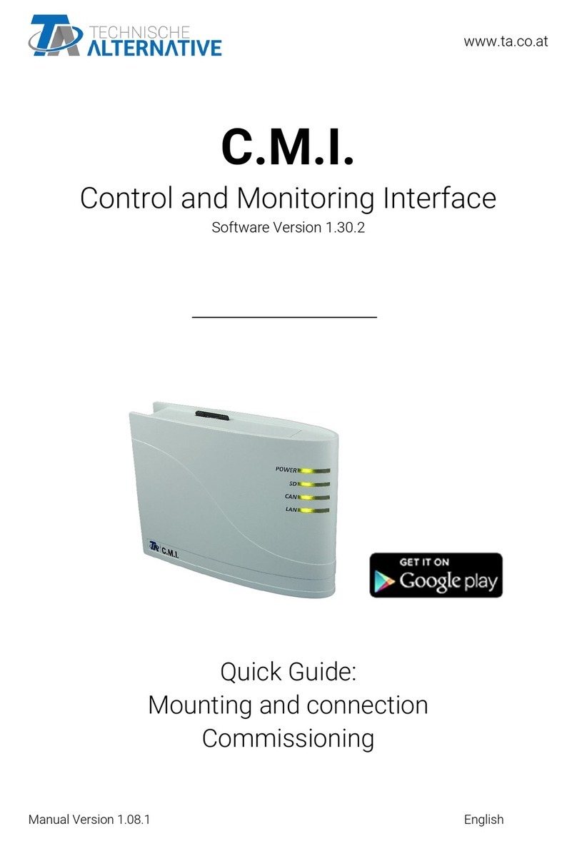
Technische Alternative C.M.I. User manual

C.M.I.
Control and Monitoring Interface
Version 1.28
User manual

Hardware / General

Function
The control and monitoring interface ("C.M.I." for short) is a web server that creates a connection between
a LAN network and the CAN bus components. This device makes it possible to load function data into
CAN bus devices, update and remote control them, illustrate online diagrams and log data. Access can
be local directly from the PC/network, via Internet and the C.M.I. web portal or via Internet through port
forwarding to the router. Data logging of devices with DL Bus is also possible. It was ensured to make
commissioning as easy as possible for computer novices as well.


Power supply
Operation of the C.M.I. requires 12V supply from CAN bus or a 12V-power pack. Power is not supplied
via DL bus.
Power consumption: typically 1.5 W
If there is only one controller (UVR1611, UVR16x2, RSM610) in the network, it is essential to use
a 12 V power supply unit to ensure power to other CAN bus subscribers that do not have their
own supply.
Data retention is also ensured without power supply.

CAN bus
Next to data transfer, the CAN bus offers also the possibility to directly access the devices in the CAN
network from the PC via browser.
Termination
Correct termination of the buses is important for use of the CAN bus to connect several devices. The
network must have terminations at the ends of the lines. For this, the C.M.I. (next to the connections)
and each CAN bus device have an appropriate jumper (term). The CAN bus must never be set up in a
star shape from one node or clamp to several devices. Rather, the correct topology is a bus line from the
first device (with terminal) to the second and so forth. The final bus connection has the terminal bridge.
Incorrect Correct
For further information on the correct topology of a CAN bus network (e.g.: cable selection, surge
protection, etc.), see the controller manuals (UVR1611, UVR16x2, RSM610).

DL bus
The C.M.I. has two DL inputs for simultaneous measurement recording from up to two controllers with
DL outputs.
Controller 1 C.M.I. Controller 2
Any cable with a cross section of 0.75 mm² and a length of up to max. 30 m can be used for the data
line (e.g. twin-strand). For longer cables, we recommend the use of shielded cable whereby the cable
shielding must be connected with the sensor earth.
If two controllers are recorded with the C.M.I., separately shielded cables must be used as protection
against crosstalk. The data link for the DL bus must likewise never be run in one cable with the CAN bus.
WARNING:
# With controllers UVR1611K and UVR1611S, output 14 (DL) can be used either as data line or as
switch output (with extra auxiliary relay). For data logging via DL bus, output 14 must therefore always
be defined as a “Data line” in the “Outputs” menu.
# With the controllers UVR1611 of the E-series (“board version“), output 14 is simultaneously used
as switch output OUTPUT 14 and data line (DL bus). For activation, the output must be parameterised
as a “Switch output”, even if the data link is to be activated. For activation of the data line, the query
“UVR1611E:” must additionally be answered with ”yes” (see additional manual for UVR1611 E).
# UVR1611 controllers from version A2.16 additionally enable the recording of network input
variables, which are handled by the C.M.I. as a virtual second UVR1611. When
parameterising output 14 as a “Data line”, the menu option NETW.EG.=>DL.: must be answered with
yes. Recording of network variables is therefore not possible, if two controllers are connected with the
C.M.I. (this note applies only to data recording via DL bus).
The scope for data recording of this 2nd virtual UVR1611 in the menu “Settings/Data logging“ of the
C.M.I.s must be set like this:

Commissioning
UVR1611 compatibility information
In order to be able to access the full range of functions, the controller must have at least operating
system version A3.25.

Delivery scope
The delivery scope of the device includes the following parts:
1 pc. Control and Monitoring Interface C.M.I.
1 pc. SD card
1 pc. 4-pole plug for the CAN bus
1 pc. 3-pole plug for the DL bus
1 pc. Brief guide
1 pc. 12V power unit (only with model: 01/CMI-NT)

Mounting and connection
The C.M.I. can be assembled either with 2 screws on an even surface or with the enclosed rapid mounting
to a TS35 DIN rail according to the EN 50022 Standard.
Dimensions:
Connections
Connections are labelled and must not be confused.
The following Figure also shows termination on the left (CAN bus).
Making the connections
Connections must be made in the following sequence
1. Connection LAN cable
2. Connection CAN bus or DL bus cable
3. Optional: power supply with power unit
(positive pole on the internal conductor, earth outside)

The POWER LED now has to be green permanently.

IP-Address
Access requires an IP address.
Network with DHCP server (standard)
The network settings are determined automatically.
Network without DHCP server
Direct C.M.I. connection– Windows PC
DHCP must be activated on the PC.PC and C.M.I. automatically gets an IP address this way. This process
can take more than 1 minute.
Fixed IP address
1. Create a Text file called fix_ip.txt with the required IP address and UTF-8 encoding in the root
directory of the SD card. The content of this file must be only an IP address (example: 192.168.0.10)
and "Enter".
2. Insert the SD card in the C.M.I.
3. During the next start, the C.M.I. adopts this IP address and deletes the txt file on the SD card.
The network settings must then be configured locally (C.M.I. menu Settings/Ethernet).
The LAN LED now has to flash green or be green permanently.

Access via browser

Access via LAN or port forwarding
1. Browser start
2. Entry in the address field of the browser: cmi (factory setting, only under Windows) or IP address
Entry „cmi“
Entry IP address (example)
The language in this window depends on the language setting in the PC operating system.
3. Authentication: Entry user name and password
The factory-set predefined user name is admin, the password also admin.
Confirmation with "OK".
The language in this window depends on the language setting in the PC operating system.
4. Now the menu of the C.M.I. appears already.

Access via C.M.I. web portal https://cmi.ta.co.at
IIf you want access via Internet, then the C.M.I can be connected via “„C.M.I. web portal“. The C.M.I.
web portal is a server that was set up by Technische Alternative.
1. Select the address https://cmi.ta.co.at, „Log in“ and click "Registration".
2. Completing the registration form and accepting the terms of use
3. After completing registration, an e-mail with an activation link will be sent to the e-mail address used
for registration. This process can take up to 30 minutes.
4. After clicking the link, the start page of the web portal is displayed already.
5. Adding the C.M.I. in the Web portal
Selection of the tab “C.M.I.s“
6. Selection “Add C.M.I.“

7. Entry of C.M.I. data
On the rear of the device is the serial number on the rating plate and the key on the key label. The key
must be entered without spaces.
Caution: All warranty and guarantee claims become void if the rating plate or key label is removed!
The "Designation“ helps with the selection of several individual C.M.I.s and is visible in the list of individual
C.M.I.s. If service by the super user (e.g. Technische Alternative) is to be allowed at all times, the
appropriate field will be checked.

After clicking on “Add“, a message about successful addition is displayed. After updating the page, the
C.M.I. appears in the list “My C.M.I.s“.
8. After updating the page, the C.M.I. appears in the list “My C.M.I.s“.
Clicking on the serial number takes you to the C.M.I. menu.
Further operation is described in chapter "C.M.I. menu".

Resetting and loading of factory settings
Briefly pressing the reset key on the rear of the C.M.I. restarts the C.M.I. (reset).
If the reset button is pressed and released while the red LEDs are still illuminated, resets the C.M.I. to
factory settings.
Caution: Pressing the reset button until the red LEDs stop being illuminated starts a firmware update with
the C.M.I. operation system saved to the SD card. Up to boot sector 1.04, the current firmware in the
"UPDATE" folder of the SD card must be called "CMI.BIN". From boot sector 1.05 onwards, it must be
called "FIRMWARE.cmi". You can identify whether the boot sector is 1.05 or above by 4 red LEDs, which
begin to glow faintly when the device is started.

Web portal cmi.ta.co.at
Other manuals for C.M.I.
2
Table of contents
Other Technische Alternative Recording Equipment manuals

