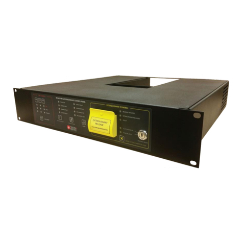
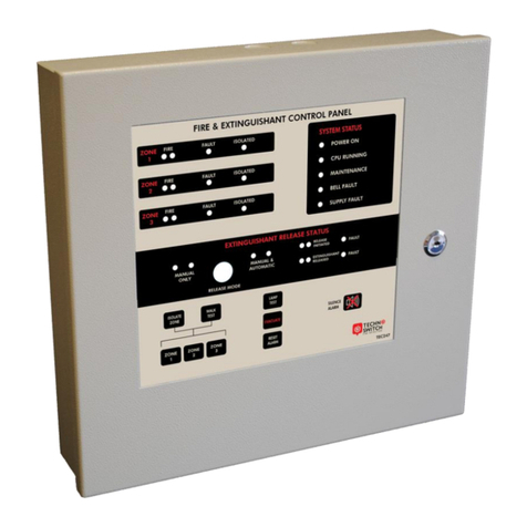
technoswitch ORYX200 Series User manual

PRMAN-0037 ORYX200 Fire Panel Range Rev 03.04 200220.docx E&OE
ORYX200 RANGE
Standard & Weatherproof
Technoswitch Conventional
Fire Control Panels
Rev 03.04

ORYX202 ORYX204 ORYX208 Conventional Fire Panel –INSTALLATION & OPERATION MANUAL
PRMAN-0037 ORYX200 Fire Panel Range Rev 03.04 200220.docx E&OE
- i -
INDEX
SPECIFICATIONS ___________________________________________________________________________ 1
1. INTRODUCTION _______________________________________________________________________ 3
1.1. STANDARDS _____________________________________________________________________________3
1.2. CAUTIONS AND WARNINGS ________________________________________________________________3
1.3. DESCRIPTION ____________________________________________________________________________4
1.4. EN 54 FUNCTIONS ________________________________________________________________________4
1.5. INSTALLATION APPROVALS________________________________________________________________5
1.5.1. Fire System Installations ____________________________________________________________5
1.5.2. Wiring Regulations _________________________________________________________________5
1.6. IDENTIFICATION OF PARTS_________________________________________________________________5
1.7. INSTALLING THE ENCLOSURE ______________________________________________________________6
1.8. WIRING INSTALLATION ____________________________________________________________________9
1.8.1. Recommended Cable Routing ________________________________________________________9
1.8.2. AC Mains Wiring__________________________________________________________________13
1.8.3. Battery Positioning & Wiring_________________________________________________________14
1.8.4. PSU Configuration ________________________________________________________________16
1.8.5. Fault Relays / Outputs _____________________________________________________________18
1.8.6. Hard Reset Function_______________________________________________________________19
1.9. External Wiring __________________________________________________________________________19
1.9.1. Relay Outputs____________________________________________________________________19
1.9.2. AUX DC Supply Output ____________________________________________________________20
1.9.3. Detection Zone Inputs _____________________________________________________________20
1.9.4. Manual Call Points ________________________________________________________________21
1.9.5. Sounder / Monitored Output Circuits __________________________________________________21
1.9.6. Input Circuits ____________________________________________________________________22
1.9.7. Repeater Connection ______________________________________________________________23
1.9.8. USB ___________________________________________________________________________23
1.10. Panel Loading ___________________________________________________________________________23
1.11. Battery Standby Calculation________________________________________________________________24
2. OPERATION _________________________________________________________________________ 25
2.1. INTRODUCTION__________________________________________________________________________25
2.1.1. Access Levels____________________________________________________________________25
2.1.2. Front Panel Controls and Indications __________________________________________________25
2.1.3. Enable Controls __________________________________________________________________28
2.1.4. Re-Sounding of Sounders (Evacuation)________________________________________________28
2.1.5. Enabling / Disabling of Zones________________________________________________________29
2.1.6. Enabling / Disabling of Sounder Circuits _______________________________________________29
2.1.7. Enabling / Disabling of Programmable Input Circuits ______________________________________29
2.1.8. One-Man Walk Test Mode __________________________________________________________30
2.1.9. Advanced Controls and Indications ___________________________________________________30
3. SERVICE AND MAINTENANCE __________________________________________________________ 31
3.1. MAINTENANCE SCHEDULE ________________________________________________________________31
3.1.1. Daily Actions_____________________________________________________________________31
3.1.2. Monthly Actions __________________________________________________________________31
3.1.3. Quarterly Actions _________________________________________________________________31
3.1.4. Annual Actions ___________________________________________________________________31
3.2. REPLACEMENT OF COMPONENTS__________________________________________________________32
3.2.1. Batteries ________________________________________________________________________32
4. APPENDICES ________________________________________________________________________ 33
4.1. APPENDIX 1 –TROUBLESHOOTING_________________________________________________________33
4.1.1. Troubleshooting Guide_____________________________________________________________33

ORYX202 ORYX204 ORYX208 Conventional Fire Panel –INSTALLATION & OPERATION MANUAL
PRMAN-0037 ORYX200 Fire Panel Range Rev 03.04 200220.docx E&OE
- ii -
- General Faults _______________________________________________________________33
- Power Supply Faults __________________________________________________________33
- Short Circuit_________________________________________________________________34
- Low Resistance Fault__________________________________________________________35
- Incorrect EOL Resistor_________________________________________________________36
- High Resistance Fault _________________________________________________________37
- False Fire Alarms and Activations ________________________________________________38
- Normal Operating Range_______________________________________________________39
5. WARRANTY__________________________________________________________________________ 39
6. DISCLAIMER_________________________________________________________________________ 39
7. REVISION INFORMATION ______________________________________________________________ 40

ORYX202 ORYX204 ORYX208 Conventional Fire Panel –INSTALLATION & OPERATION MANUAL
PRMAN-0037 ORYX200 Fire Panel Range Rev 03.04 200220.docx E&OE
- 1 -
SPECIFICATIONS
Item
Specification Detail
Part Numbers
ORYX202; ORYX204; ORYX208;
ORYX202-W; ORYX204-W; ORYX208-W;
ORYX202-WDIN; ORYX204-WDIN; ORYX208-WDIN
Enclosure
Mild Steel IP30, Matt Light Grey (ANP 37035)
Dimensions H x W x D (mm)
- ORYX202 & ORYX204 Standard
- ORYX202 & ORYX204 Weatherproof
- ORYX208 Standard
- ORYX208 Weatherproof
270 x 322 x 102
450 x 391 x 120
391 x 388 x 108
500 x 510 x 135
Environmental
-5 °C to +40 °C
Humidity
95% RH, Non-condensing
Weight
- ORYX202 & ORYX204 Standard
- ORYX202 & ORYX204 Weatherproof
- ORYX208 Standard
- ORYX208 Weatherproof
± 3.0 kg (excl. Batteries)
± 6.5 kg (excl. Batteries)
± 4.5 kg (excl. Batteries)
± 9.0 kg (excl. Batteries)
Cable Entries
- ORYX202 & ORYX204 Standard
- ORYX202 & ORYX204 Weatherproof
- ORYX208 Standard
- ORYX208 Weatherproof
4x 25 mm & 4x 20 mm on top, 4x 25 mm & 2x 20 mm on back
2x 25 mm & 5x 20 mm on bottom
4x 25 mm & 6x 20 mm on top, 4x 25 mm & 4x 20 mm on back
4x 25 mm & 5x 20 mm on bottom
LED Indicators
- ORYX202
- ORYX204
- ORYX208
3x Fire, 16x Fault (11 Hidden below lid), 8x Control & Information indications
5x Fire, 18x Fault (11 Hidden below lid), 8x Control & Information indications
9x Fire, 22x Fault (11 Hidden below lid), 8x Control & Information indications
Key Switch
Enable Controls
Event Log
900 log events
Mains Supply
Quiescent Load
- ORYX202
- ORYX204
- ORYX208
Alarm Load
- ORYX202
- ORYX204
- ORYX208
100 –240 V AC (+/- 10%), 50/60 Hz, 1.0 A max
72 mA @ 110 V AC / 63 mA @ 240 V AC
76 mA @ 110 V AC / 67 mA @ 240 V AC
103 mA @ 110 V AC / 76 mA @ 240 V AC
145 mA @ 110 V AC / 96 mA @ 240 V AC
202 mA @ 110 V AC / 120 mA @ 240 V AC
230 mA @ 110 V AC / 130 mA @ 240 V AC
Power Supply
27.5 V DC, Switch Mode, 1.2 A load, 0.5 A max battery charging
PCB Quiescent Load
- ORYX202
- ORYX204
- ORYX208
100 mA @ 27.5 V DC
118 mA @ 27.5 V DC
170 mA @ 27.5 V DC
PCB Alarm Load
- ORYX202
- ORYX204
- ORYX208
260 mA @ 27.5 V DC
380 mA @ 27.5 V DC
458 mA @ 27.5 V DC
AUX Supply Output
27.5 V DC, 0.5 A
Battery Capacity
- ORYX202, ORYX204
- ORYX208
24 V 7 Ah
24 V 7 Ah, 12 Ah or 17 Ah
Battery Charging Current
0.5 A max temperature compensated
Number of Fire Zones
2, 4 or 8 Zones
Zone EOL
3k3 Ω
Zone Alarm Thresholds
400 –800 Ω
Sounder Outputs
2 rated at 300 mA each
Sounder EOL
3k3 Ω
General Fire Relay
30 V AC/DC, 1 A maximum
General Fault Relay
30 V AC/DC, 1 A maximum

ORYX202 ORYX204 ORYX208 Conventional Fire Panel –INSTALLATION & OPERATION MANUAL
PRMAN-0037 ORYX200 Fire Panel Range Rev 03.04 200220.docx E&OE
- 2 -
Item
Specification Detail
Zone Fire Relays
- ORYX202
- ORYX204
- ORYX208
2 rated 30 V AC/DC, 1 A maximum
4 rated 30 V AC/DC, 1 A maximum
8 rated 30 V AC/DC, 1 A maximum
Inputs
2 fully monitored as per below
Monitored Inputs EOL
3k3 Ω
Monitored Inputs Alarm Threshold
400 –800 Ω
Repeater Connection
Two-wire RS485 @ 1,200 metre max
Number of Repeaters on Communication
Bus
7 (Seven)

ORYX202 ORYX204 ORYX208 Conventional Fire Panel –INSTALLATION & OPERATION MANUAL
PRMAN-0037 ORYX200 Fire Panel Range Rev 03.04 200220.docx E&OE
- 3 -
1. INTRODUCTION
1.1. STANDARDS
This range of Conventional Fire Alarm Control Panels have been designed to comply with the following
standards:
EN 54-2: 1997 +A1:2006 Control and Indicating Equipment
EN 54-4: 1997 +A1:2002 +A1:2006 Power Supply Equipment
EN 60950: 2000 Safety of Information Technology Equipment
EN 50130-4: 1996 Product Family Standard
Electromagnetic Compatibility Directive 89/336/EEC (and the amending directive 92/23/EEC)
Low Voltage Directive 73/23/EEC
In addition to the basic requirements of EN 54, the Fire Alarm Control Panel offers the following EN 54 optional
features with requirements and additional functions not covered by EN 54:
Control & Indicating Optional Functions
EN 54-2 Clause
Outputs to Fire Alarm Devices
7.8
Total Loss of Power
8.4
Test Condition
10
Power Supply Equipment Optional Functions
EN 54-4 Clause
Operation from a Main Power Supply
5.1
Operation from a Standby Battery
5.2
Monitor and Charge the Standby Battery
5.3
Recognise and Notify Supply Faults
5.4
Additional Functions
Auxiliary Power Supply Output
Auxiliary Relay Outputs
1.2. CAUTIONS AND WARNINGS
STOP
Before commencing with installation or operation of the panel, please read this manual
carefully.
If you are unclear on any point DO NOT proceed. Contact the manufacturer or supplier
for clarification and guidance.
Only trained service personnel should undertake the installation, programming and
maintenance of this equipment.
This product has been designed to comply with the requirements of the Low Voltage
Safety and the EMC Directives. Failure to follow the installation instructions may
compromise its adherence to these standards.
This equipment is constructed with static sensitive components.
Observe anti-static precautions at all times when handling printed circuit boards.
Wear an anti-static earth strap connected to panel enclosure earth point.
Before installing or removing any printed circuit boards remove all sources of power
(Mains and Battery).

ORYX202 ORYX204 ORYX208 Conventional Fire Panel –INSTALLATION & OPERATION MANUAL
PRMAN-0037 ORYX200 Fire Panel Range Rev 03.04 200220.docx E&OE
- 4 -
This Fire Alarm Control Panel is compliant with the requirements of EN 54 parts 2 and
4 (1998).
Where appropriate, reference is made in this manual to the relevant sections of the
EN 54 standard for clarification and to ensure that the installation is compliant with the
requirements of EN 54.
1.3. DESCRIPTION
This manual covers the installation, programming and commissioning of the ORYX202, ORYX204 and
ORYX208 Fire Alarm Control Panels. This manual provides generic operational, programming and installation
information.
▪The ORYX202 is a 2 Zone Conventional Fire Alarm Panel.
▪The ORYX204 is a 4 Zone Conventional Fire Alarm Panel.
▪The ORYX208 is an 8 Zone Conventional Fire Alarm Panel.
▪All models are also available in a Weatherproof IP65 rated version.
▪Refer to Section 2 OPERATION, page 25, or the Basic Operating Instructions document PRBOI-0007
ORYX200 Range for simplified user instructions.
▪2, 4 and 8 Zone Repeater Panels are available for the ORYX Fire Panel Range.
1.4. EN 54 FUNCTIONS
This Fire Alarm Control Panel is compliant with the requirements of EN 54-2 (1997) +
A1:2006 and EN 54-4 (1997).
In addition to the basic requirements, the following optional functions are provided,
and these comply with the requirements of EN 54.
CIE Optional Functions
EN 54-2 Clause
Indication
Output
Controls
Outputs to Fire Alarm Devices
Output to Fault Routing Equipment
Test Condition
7.8
8.9
10
PSE Functions
EN 54-4 Clause
Operation from a Main Power Supply
Operation from a Standby Battery
Monitor and Charge the Standby Battery
Recognise and Notify Supply Faults
5.1
5.2
5.3
5.4
This Fire Alarm Control Panel also supports additional functions that are not covered by
EN 54. These are as follows:
Additional Function
Refer to
Paragraphs
Auxiliary Power Supply Output
Auxiliary Relay Outputs
1.9.2
1.9.1

ORYX202 ORYX204 ORYX208 Conventional Fire Panel –INSTALLATION & OPERATION MANUAL
PRMAN-0037 ORYX200 Fire Panel Range Rev 03.04 200220.docx E&OE
- 5 -
In addition to the mandatory requirements of EN 54 Part 2, the Control and Indicating Equipment (CIE)
supports the following optional features with requirements:
Section 7.8
Outputs to Fire Alarm Devices
The CIE has provision for connection to Fire Alarm Devices. It is possible to Silence and Resound
the alarms at Level 2. Refer to 1.9.1 Relay Outputs, page 19 for further information.
Section 9.5
Disablement of Points
The CIE has provision for enabling and disabling signals from points.
Refer to 0
Enabling / Disabling of Zones; 2.1.6 Enabling / Disabling of Sounder Circuits; and 2.1.7 Enabling /
Disabling of Programmable Input Circuits on pages 29–29 for further information.
Section 10
Test Condition
The CIE has provision for testing the installation on a per zone basis. Refer to 2.1.8 One-Man
Walk Test Mode, page 30 for further information.
1.5. INSTALLATION APPROVALS
1.5.1. FIRE SYSTEM INSTALLATIONS
The panel must be installed and configured for operation in accordance with these instructions and the
applicable code of practice or national standard regulations for fire systems installation appropriate to the
country and location of the installation. In South Africa this would be SANS 10139.
1.5.2. WIRING REGULATIONS
The panel and system must be installed in accordance with these instructions and the applicable wiring codes
and regulations (for example BS7671) appropriate to the country and location of the installation.
1.6. IDENTIFICATION OF PARTS
FIGURE 1 Identification of Major Panel Parts

ORYX202 ORYX204 ORYX208 Conventional Fire Panel –INSTALLATION & OPERATION MANUAL
PRMAN-0037 ORYX200 Fire Panel Range Rev 03.04 200220.docx E&OE
- 6 -
1.7. INSTALLING THE ENCLOSURE
The panel is heavy when the batteries are installed. Use the appropriate fixing hardware to secure
the panel to the wall. Observe recommended lifting practices to guard against spinal injury.
See table below for maximum weights:
Enclosure
Weight
Maximum
Battery
Overall Maximum
Weight
ORYX202 & ORYX204 Standard
3 kg
7 Ah 2.5 kg
5.5 kg
ORYX202 & ORYX204 Weatherproof
6.5 kg
7 Ah 2.5 kg
9 kg
ORYX208 Standard
4.5 kg
17 Ah 5.5 kg
10 kg
ORYX208 Weatherproof
9 kg
17 Ah 5.5 kg
14.5 kg
The Standard Enclosure covers are provided with a key lock assembly for securing the hinged door to the back
box. Insert and turn the key anti-clockwise to open the enclosure.
The Weatherproof Enclosure is provided with a padlock assembly for securing the hinged door to the back box.
Lift the lever and turn it anti-clockwise to open the enclosure.
The chassis plate (fitted with the Main PCB) has pluggable connectors and a 90° swivel system allowing for the
chassis plate to be removed easily, and also providing easy access to the batteries.
FIGURE 2 Installing the Enclosure
It is recommended that the chassis plate of the Standard Enclosure be removed before fitting the panel to the
wall. To remove the chassis:
▪Unhook the chassis plate from the wing brackets and swivel 90° to slide into the vertical lock position as
indicated in FIGURE 2.
▪Unplug the 2-way connector feeding the 24 V DC supply to the Main PCB.
▪Unplug the communications cable (grey ribbon cable).
▪Disconnect the earth cable connecting the chassis to the spade terminal on the rear enclosure.
▪Carefully remove the chassis from the rear enclosure by pulling it forward out of the vertical locking position.
Put in a safe place to prevent accidental damage.
NB: Do not lift the chassis by holding onto any of the printed circuit cards. Hold the chassis by the metal
plate only.

ORYX202 ORYX204 ORYX208 Conventional Fire Panel –INSTALLATION & OPERATION MANUAL
PRMAN-0037 ORYX200 Fire Panel Range Rev 03.04 200220.docx E&OE
- 7 -
Firstly, remove the required knockouts for the installation wiring. There are sufficient knockouts on the top of the
Standard Enclosure for all installation wiring. In addition, there are knockouts at the top of the back wall, if
required, for rear entry cabling.
The Weatherproof Enclosure has cable entry points provided at the bottom of the enclosure. Remove the rubber
glands to utilise the cable entry point. Cable entry should only be from the bottom through the provided points
with compression glands to ensure integrity of the enclosure is maintained.
The Standard Enclosures are provided with three fixing points and the Weatherproof Enclosures are provided
with 4 externally positioned fixing points.
FIGURE 3 and FIGURE 4 show the positions of the mounting holes and dimensions of each Standard
Enclosure. FIGURE 5 and FIGURE 6 show the positions of the mounting holes and dimensions of each
Weatherproof Enclosure. Use all mounting holes provided to ensure the panel is held securely to the wall.
It is recommended that an additional sun shield be fitted, should the panel be exposed to direct sunlight. This
will assist to limit temperate build up in the enclosure.
The Standard Enclosure is provided with cable tie points that are required to properly secure the field cabling.
Ensure the cable tie points are bent forward for use before securing the enclosure to the wall.
The Weatherproof panel has cable channels with cable tie points on both sides of the enclosure. The cable
channels should be used to route field cables to the pluggable connectors of the Main PCB. If the DIN Rail
option was selected, the harnesses between the pluggable connectors and DIN Rail modules will be pre-
installed.
Drill the required holes in the supporting wall using a drill bit 8 or 10 mm diameter and plug with a suitable
40 mm or longer expansion plugs. Affix the panel to the wall with M6 screws or No.10 screws for the Standard
Enclosure and with M8 screws for the Weatherproof Enclosure. Use appropriate fixings to support the weight
including the batteries.
Ensure that there is sufficient space to allow the door to be opened when the panel is mounted.
Finally, use a brush or compressed air to remove any dust or debris from inside the enclosure.
FIGURE 3 ORYX202 & ORYX204 Standard Panel

ORYX202 ORYX204 ORYX208 Conventional Fire Panel –INSTALLATION & OPERATION MANUAL
PRMAN-0037 ORYX200 Fire Panel Range Rev 03.04 200220.docx E&OE
- 8 -
FIGURE 4 ORYX208 Standard Panel
FIGURE 5 ORYX202 & ORYX204 Weatherproof Panel

ORYX202 ORYX204 ORYX208 Conventional Fire Panel –INSTALLATION & OPERATION MANUAL
PRMAN-0037 ORYX200 Fire Panel Range Rev 03.04 200220.docx E&OE
- 9 -
FIGURE 6 ORYX208 Weatherproof Panel
1.8. WIRING INSTALLATION
All electrical wiring installation work should be carried out in accordance with the code of practice or applicable
national standards appropriate to the country of installation.
To maintain electrical integrity all zone, input, output and communication line wiring should be segregated from
the AC Mains wiring and be wired using cable with insulation suitable for the application.
To minimise the effects of EMC interference, all data wiring circuits should be wired with a twisted pair of
conductors with a cross sectional area suitable for the loading conditions.
In areas where cabling may come into contact with high frequency interference, such as portable radio
transceivers etc., the data wiring cable should be of a twisted pair construction within an overall screen. Care
should be taken to correctly terminate this screen, refer to the appropriate sections of this manual for further
information for each circuit type.
NB: Minimum / Maximum cable size for all external connections is limited to 0.5 mm² / 2.5 mm²
(22 –14 AWG).
1.8.1. RECOMMENDED CABLE ROUTING
It is recommended that the typical routing arrangement shown in 0 and FIGURE 8 be followed.
Segregate the low voltage wiring (Zone Circuits, Sounder Circuits and AUX Supply) from the AC Mains Wiring.
Segregate any wiring connected to the relay contacts.
Refer to specific sections on how to install AC Mains Input and Loop, Sounder, Relay and AUX Outputs Circuits.

ORYX202 ORYX204 ORYX208 Conventional Fire Panel –INSTALLATION & OPERATION MANUAL
PRMAN-0037 ORYX200 Fire Panel Range Rev 03.04 200220.docx E&OE
- 10 -
FIGURE 7 Internal Arrangement Showing Recommended Cable Routing for the ORYX202 & ORYX204
Panels
FIGURE 8 Internal Arrangement Showing Recommended Cable Routing for the ORYX208 Panel

ORYX202 ORYX204 ORYX208 Conventional Fire Panel –INSTALLATION & OPERATION MANUAL
PRMAN-0037 ORYX200 Fire Panel Range Rev 03.04 200220.docx E&OE
- 11 -
1.8.1.1. WEATHERPROOF PANEL WITH DIN RAIL TERMINATION OPTION
For the Weatherproof Enclosure with DIN Rail mounted modules it is recommended that the routing
arrangement shown in FIGURE 9 and FIGURE 10 be followed.
External wiring indicated in section 1.8.3 Battery Positioning & Wiring, page 14, should be terminated to the
DIN Rail modules. A layout of the DIN Rail terminal connections is shown in FIGURE 11 and is also visible on
the inside of the panel door.
FIGURE 9 Internal Arrangement Showing Recommended Cable Routing in the DIN Rail Mounted ORYX202
& ORYX204 Weatherproof Enclosures
FIGURE 10 Internal Arrangement Showing Recommended Cable Routing in the DIN Rail Mounted ORYX208
Weatherproof Enclosure

ORYX202 ORYX204 ORYX208 Conventional Fire Panel –INSTALLATION & OPERATION MANUAL
PRMAN-0037 ORYX200 Fire Panel Range Rev 03.04 200220.docx E&OE
- 12 -
FIGURE 11 4 Zone Terminal Connection Layout of Weatherproof Panel with DIN Rail
FIGURE 12 8 Zone Terminal Connection Layout of Weatherproof Panel with DIN Rail
1.8.1.2. WEATHERPROOF PANEL WITHOUT DIN RAIL OPTION
For the Weatherproof Enclosure without DIN Rail mounted modules, it is recommended that the routing
arrangement shown in FIGURE 13 be followed.
External wiring indicated in section 1.8.3 Battery Positioning & Wiring, page 14, should be terminated to the
pluggable connectors on the chassis plate PCB.
FIGURE 13 Internal Arrangement Showing Recommended Routing of Cables without the DIN Rail Mounted
Modules in the ORYX204 Weatherproof Panel

ORYX202 ORYX204 ORYX208 Conventional Fire Panel –INSTALLATION & OPERATION MANUAL
PRMAN-0037 ORYX200 Fire Panel Range Rev 03.04 200220.docx E&OE
- 13 -
FIGURE 14 Internal Arrangement Showing Recommended Routing of Cables without the DIN Rail Mounted
Modules in the ORYX208 Weatherproof Panel
1.8.2. AC MAINS WIRING
Route the high voltage Mains AC wiring into the
enclosure at the upper right corner only. Keep the
AC wiring away from the circuit boards and all other
wiring.
The panels must be connected to the
supply earth through the power
cable.
The Mains Input connector is shown
in FIGURE 15. Note the positions of the earth,
neutral and live terminal connections. These are
clearly marked on the label next to the connector.
The connector block contains an integral fuse
holder.
Secure the Mains Input wiring by tie wrap as close
to the terminal block as possible.
Connect the Control Panel to the Mains Supply via
a readily accessible disconnect-device (Isolation
Switch) and suitable earth fault protection
incorporated in the building installation wiring. The
Mains cable should be 0.75 mm2cable rated at
250 V AC and fused via a 1 A anti-surge fuse.
The fuse holder is a pull-out type that can switch off
the power supply, if required. We do however
recommend that the power supply be switched off
at the AC Mains Supply indicator.
FIGURE 15 AC Mains Terminations
The fuse is rated as follows:
T 1A H 250 V AC
Replace with correct rating and specification
only.

ORYX202 ORYX204 ORYX208 Conventional Fire Panel –INSTALLATION & OPERATION MANUAL
PRMAN-0037 ORYX200 Fire Panel Range Rev 03.04 200220.docx E&OE
- 14 -
1.8.3. BATTERY POSITIONING & WIRING
FIGURE 16 Standard Panel Battery Positioning for the ORYX202 & ORYX204 Panel
FIGURE 17 Weatherproof Panel Battery Positioning for the ORYX202 & ORYX204 Panel

ORYX202 ORYX204 ORYX208 Conventional Fire Panel –INSTALLATION & OPERATION MANUAL
PRMAN-0037 ORYX200 Fire Panel Range Rev 03.04 200220.docx E&OE
- 15 -
The panel requires 2x (two) 12 V DC batteries
connected in series for standby operation.
The battery harness is already pre-fitted.
Use the Red & Black leads of the provided
harness to connect the batteries to the BATT
+VCC and BATTGND terminals on the PSU.
The short (Blue) lead provided is used to
connect the batteries as shown in FIGURE 18.
Refer to the SPECIFICATIONS Section,
page 1 of this manual for minimum and
maximum battery sizes allowed.
NB: OBSERVE POLARITY OF CONNECTIONS!
FIGURE 18 Battery Wiring
NB: If no AC input voltage is present and the battery voltage falls below 20 V DC, the PSU will automatically
shut down. Once AC Mains Supply has been restored, the PSU will automatically reset and restore the
27.5 V DC Output.
NB: Start-from-Batteries button has been added to assist if no AC mains supply is present on site. The
batteries will need to be fully charged before using this function.
Remove the load from the output. Press and hold Start-from-Batteries button until CPU running LED flashes.
Do not continuously run your power supply in this mode.
Do not make the final battery connections until the installation wiring is completed and the system
is to be powered up.
Always connect the AC Mains input before connecting the battery.
New batteries require ‘top-up charging’ before installation.
NB: Ensure that the panel is configured with the correct date and time settings. Refer to Application Note
PRAPN-0008 ORYX200 Event Log Retrieval for assistance in this regard.

ORYX202 ORYX204 ORYX208 Conventional Fire Panel –INSTALLATION & OPERATION MANUAL
PRMAN-0037 ORYX200 Fire Panel Range Rev 03.04 200220.docx E&OE
- 16 -
1.8.4. PSU CONFIGURATION
The internal power supply is a high efficiency switch-mode power supply with an input AC voltage range of
100 –240 V AC. The power supply provides the following:
▪27.5 V DC to the fire control panel electronic circuits
▪Battery charging and monitoring
▪LED fault indication
▪Two relay outputs, one for common PSU fault and the other for an AC Input Fault
FIGURE 19 PSU Configuration

ORYX202 ORYX204 ORYX208 Conventional Fire Panel –INSTALLATION & OPERATION MANUAL
PRMAN-0037 ORYX200 Fire Panel Range Rev 03.04 200220.docx E&OE
- 17 -
1.8.4.1. PSU LED INDICATIONS
The power supply continuously monitors the AC supply, battery connection, battery charging voltage and output
supply voltage and will bring up the appropriate Fault conditions should these be outside of specifications.
These faults will be indicated by the respective LEDs on the Power Supply PCB –see FIGURE 20 below.
FIGURE 20 PSU LED Indications
1.8.4.2. PSU FAULT INDICATIONS
▪AC Fault
The AC Fault LED, Supply Fault Relay and General Fault Relay activates. When the Fault is cleared,
indications and relays restore immediately.
▪Earth Fault
The Earth Fault LED and General Fault Relay activates. When Fault is cleared, indications and relay
restore within 30 seconds.
▪Charger Fault
The Charger Fault LED and General Fault Relay activates. When the Fault is cleared, indications and relay
restore within 30 seconds.
▪Battery Fault
The Battery Fault LED and General Fault relay activate. When the Fault is cleared, a panel reset or hard
reset on the PSU is required to restore indications and relays, or alternatively the fault will clear once a
successful load test was complete.
▪Output Fault
The maximum continuous operating output current is 1.2 A. Should you exceed 1.2 A, three modes are
provided to protect the output or to provide additional current, depending on the amount of current draw.
▪Boost Mode
- Should the current draw exceed 1.2 A, the 24 V DC output Fault LED will flash, and the battery
charger circuit will be shut down.
- If the 24 V DC output current draw exceeds 1.2 A, but is less than 1.8 A, for more than
10 minutes, the General Fault Relay and the 24 V DC output LED will be on solid. The Charger
Fault LED will also be solid on to indicate the charger is still off due the additional current drawn
on the output.
- The 24 V DC output remains active.
- When current draw is reduced to below 1.2 A, LED indications, relay and charger will restore
automatically within 30 seconds.
▪Overload Mode
- Should the current draw exceed 1.8 A, the 24 V DC output Fault LED will flash and the battery
charger circuit will be shut down.
- If the 24 V DC output current draw exceeds 1.8 A, but is less than 2.5 A, for more than
10 minutes, the General Fault Relay and the 24 V DC output LED will be on solid.
- The output will shut down and attempt to restore every 30 seconds; this will continue until the load
is reduced to below 1.8 A.
- The charger will switch back on automatically.
Other manuals for ORYX200 Series
1
Table of contents
Other technoswitch Control Panel manuals
Popular Control Panel manuals by other brands
Climate Technologies
Climate Technologies TEK600 Series owner's manual

ART+SOUND
ART+SOUND WP-8000C user manual
wattstopper
wattstopper Legrand Miro MRDS10 quick start guide
Airmax
Airmax 653945 installation instructions
Fire-Lite
Fire-Lite MS-2 instruction manual

Tecnocontrol
Tecnocontrol CITY CE400 User instructions
