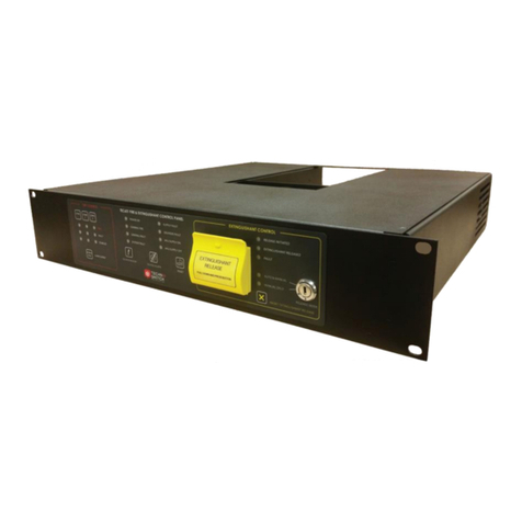
technoswitch TEC247 User manual

DOC NO. PRMAN-0003 TEC247 Rev 04.12 191209.docx Revised: 2019-12
TEC247
Technoswitch Conventional
Fire & Extinguishing
Control Panel
Rev 04.11

TEC247 Fire & Extinguishant Control Panel –INSTALLATION & OPERATION MANUAL
DOC NO. PRMAN-0003 TEC247 Rev 04.12 191209.docx - i - Revised: 2019-12
Contents
1. SYSTEM DESCRIPTION____________________________________________________ 2
2. SYSTEM COMPONENTS ___________________________________________________ 2
3. CONNECTION DIAGRAMS__________________________________________________ 3
4. POWER SUPPLY _________________________________________________________ 4
4.1 AC Mains Wiring_____________________________________________________________5
4.2 Battery Wiring_______________________________________________________________5
4.3 27.5 V DC Wiring ____________________________________________________________6
4.4 Fault Indications _____________________________________________________________6
5. FAULT RELAYS/OUTPUTS _________________________________________________ 7
5.1 Hard and Soft Reset Function __________________________________________________8
5.2 Fire Zone Circuits ____________________________________________________________8
5.3 Manual Call Points ___________________________________________________________9
5.4 Bell Outputs ________________________________________________________________9
5.5 Extinguishant Release Detonator/Solenoid _______________________________________10
5.6 Common Outputs ___________________________________________________________10
5.7 Extinguishant Control ________________________________________________________10
5.8 Manual Extinguishant Release Call Point (On Remote MCP Contacts) _________________10
5.9 Door Switch _______________________________________________________________11
5.10 Initiate Time Delay __________________________________________________________11
6. SYSTEM OPERATION ____________________________________________________ 11
6.1 System Status Indicators _____________________________________________________11
7. TROUBLESHOOTING_____________________________________________________ 13
8. TECHNO TIP ____________________________________________________________ 14
9. TECHNICAL SPECIFICATIONS _____________________________________________ 15
10. WARRANTY ____________________________________________________________ 15
11. DISCLAIMER____________________________________________________________ 15
12. REVISION INFORMATION _________________________________________________ 15

TEC247 Fire & Extinguishant Control Panel –INSTALLATION & OPERATION MANUAL
DOC NO. PRMAN-0003 TEC247 Rev 04.12 191209.docx - 2 - E. &O.E.
1. SYSTEM DESCRIPTION
A number of fire detection devices are wired into zones. The fire control panel monitors the circuits of these
detection zones and will react on detecting either a Fire or a Fault condition within a zone.
In the case of a Fault condition (detector fault, short or open circuit fault) the panel’s internal buzzer will sound and
the respective zone’s FAULT LED on the facia will flash or remain on. The common fault relay on the motherboard
will also change state. This is under normal circumstances energised (fail safe) and thus will be de-energised on
Fault condition.
In the case of a Fire condition, the panel’s internal buzzer will sound and the respective zone’s FIRE LED will flash.
The bell output contacts on the motherboard will supply 24 V DC power. Three other standard outputs will also
operate. These outputs are the Common Fire Alarm output, the Fire Brigade output and the Zone Repeat relay.
Fire Zone 1 and Zone 2 are connected to the extinguishant release output. An alarm from both these zones will
initiate the discharge cycle if the control panel is in automatic mode. The panel may be switched to manual release
mode in order to de-activate the automatic extinguishing mode.
A yellow extinguishant release Manual Call Point (MCP) has been supplied with the panel. This may be wired to
the remote MCP contact of the control panel. A 680 resistor must be wired to this Manual Call Point (see 5.3
Manual Call Points on page 9).
▪System Status indications include Power On, CPU Running, Bell Fault, Maintenance Mode, Supply Fault.
▪Zone indications include Fire Alarm, Fault and Isolate indications.
▪Extinguishing Status indications include Initiate Release + Fault, Extinguishant Released + Fault, Manual
Only, and Auto & Manual.
User functions include Silence, Reset, Evacuate, Lamp test, Zone Isolate, and Walk-test (see 6 SYSTEM
OPERATION on page 11).
2. SYSTEM COMPONENTS
NB: Version 6 and above CPU and motherboards are not backward compatible with version 5 PCBs although
boxes, keypads and power supplies are common. You will find the version label on the CPU board and
motherboards.
Control Panel
▪Enclosure with membrane keypad, auto/manual key switch, motherboard,
CPU board and Power supply board.
- CPU labelled –T247CPU (Product Code: PCB-TEC247-CPUx)
- Motherboard labelled –T247MB (Product Code: PCB-TEC247-MBx)
- Power Supply –PCB-PSU2A
Detection Devices
Ionisation or optical smoke detectors, heat detectors and manual call points.
Specialised equipment such as linear heat detection, optical beam detectors,
aspirating smoke detectors, and UV/IR flame detectors may be used -
modifications to the connections may apply with these.
Warning Devices
Sirens, bells, beacons and combined beacon/siren may be used.
Secondary Devices
Extinguishant interface, repeater panels, mimic panels, GPRS communicators,
telediallers, relays and/or transmitters may be connected.
Some of these may need additional interface boards.
Manual
Extinguishant
Release
Yellow surface mount MCP with hinged flap and seal.

TEC247 Fire & Extinguishant Control Panel –INSTALLATION & OPERATION MANUAL
DOC NO. PRMAN-0003 TEC247 Rev 04.12 191209.docx - 3 - E. &O.E.
3. CONNECTION DIAGRAMS
FIGURE 1 TEC247 –CONNECTION DIAGRAM

TEC247 Fire & Extinguishant Control Panel –INSTALLATION & OPERATION MANUAL
DOC NO. PRMAN-0003 TEC247 Rev 04.12 191209.docx - 4 - E. &O.E.
4. POWER SUPPLY
The internal power supply is a high efficiency switch-mode power supply with an input AC voltage range of
100-250 V AC. The power supply provides the following:
▪27.5 V DC to the fire control panel electronic circuits
▪Battery charging and monitoring
▪LED fault indication
▪Two relay outputs, one for Common PSU Fault and the other for an AC Input Fault
FIGURE 2 PCB-PSU2A –POWER SUPPLY BOARD
NB: If an external power supply is used to power the panel, all warranty claims will be null and void.
NB: Care must be taken to earth the panel correctly. An earth lug is located inside the enclosure for this
purpose. Appropriate lugs should be used to terminate all cables.
NB: Terminal blocks should be opened counter-clockwise at least 5 turns before inserting a cable and
tightening the contact. Failure to do so could cause malfunction of the installation.

TEC247 Fire & Extinguishant Control Panel –INSTALLATION & OPERATION MANUAL
DOC NO. PRMAN-0003 TEC247 Rev 04.12 191209.docx - 5 - E. &O.E.
4.1 AC MAINS WIRING
The high voltage AC mains wiring should be routed into the enclosure via a suitable knockout and kept away from
any circuit boards and all other wiring.
NB: The panel must be connected to the supply earth through the power cable.
The AC mains input connector is shown in the diagram below. Please take note of the positions of the Earth,
Neutral and Live terminal connections which are clearly labelled. Secure the AC wiring using a tie wrap as close to
the terminal block as possible.
FIGURE 3 AC INPUT
The AC Mains Input Fuse is located next to the AC Input Terminal. The Fuse holder is a pull-out type that can be
used to switch the power supply off, if required. We do however recommend that the power supply be switched off
at the AC mains supply isolator.
The fuse is rated as T 1A H 250 V AC.
NB: When external 24 V DC power supplies are used to power auxiliary devices, the earth of all the external
power supplies must be joined with the earth of the fire control panel.
4.2 BATTERY WIRING
The power supply is designed to charge two 12 V DC batteries connected in series. Use the Red & Black leads
provided to connect the batteries to the BATT +VCC and BATT GND terminals on the PSU. The short (Blue) lead
provided is used to connect the batteries as shown in FIGURE 4 below:
FIGURE 4 BATTERY WIRING
NB: Observe polarity of connections!!
NB: If no AC input voltage is present and the battery voltage falls below 20 V DC, the PSU will automatically
shut down. Once 220 V AC has been restored, the PSU will automatically reset and restore the 27.5 V DC
supply to the control panel.
NB: Start-from-Batteries button has been added to assist if no AC mains supply is present on site. The
batteries will need to be fully charged before using this function.
Press and hold Start-from-Batteries button until CPU running LED flashes. Do not continuously run your power supply in
this mode.

TEC247 Fire & Extinguishant Control Panel –INSTALLATION & OPERATION MANUAL
DOC NO. PRMAN-0003 TEC247 Rev 04.12 191209.docx - 6 - E. &O.E.
4.3 27.5 V DC WIRING
The motherboard of the control panel is supplied with 27.5 V DC from the power supply.
In addition, the operating status of the power supply is communicated to the control panel via a communications
lead. This wiring harness is fitted as per FIGURE 5 27.5 V DC Wiring Harness.
The 27.5 V DC output on the power supply can also be used as an AUX Supply Output by means of wiring the
Output GND (negative) and Output +VCC (positive) to your auxiliary device.
FIGURE 5 27.5 V DC WIRING HARNESS
4.4 FAULT INDICATIONS
The power supply continuously monitors the AC supply, battery connection, battery charging voltage and output
supply voltage, and will bring up the appropriate Fault conditions should these be outside of specifications. These
faults will be indicated by the respective LEDs on the Power Supply PCB - see FIGURE 6:
FIGURE 6 PSU LED INDICATIONS
▪AC Fault
The AC Fault LED, Supply Fault Relay and General Fault Relay activates. When the Fault is cleared, indications
and relays restore immediately.
▪Load Test
The Load Test LED is on for 30 seconds whilst test is conducted, battery charger is switched off (successful test =
Normal, failed test = Battery Fault). First load test takes place 10 minutes after start-up and every 4 hours
thereafter.
▪Charger Fault
The Charger Fault LED and General Fault Relay activates. When the Fault is cleared, a panel reset is required to
restore indications and relays, or alternatively a hard reset of the PSU.
▪Battery Fault
The Battery Fault LED and General Fault relay activate. When the Fault is cleared, a panel reset is required to
restore indications and relays, or alternatively a hard reset of the PSU.
▪Output Fault
The maximum continuous operating output current is 1.2 A. Should you exceed 1.2 A, two modes are provided to
protect the output, or to provide additional current, depending on the amount of current draw:
▪Boost Mode
- Should the current draw exceed 1.2 A, the 24 V DC Output Fault LED will flash and the battery charger circuit
will be shut down.
- If the 24 V DC output current draw exceeds 1.2 A, but is less than 1.8 A, for more than 10 minutes, the
General Fault relay and the 24 V DC output LED will be on solid. DC Supply Fault Output will be 0 V DC.

TEC247 Fire & Extinguishant Control Panel –INSTALLATION & OPERATION MANUAL
DOC NO. PRMAN-0003 TEC247 Rev 04.12 191209.docx - 7 - E. &O.E.
- The Charger Fault LED will be solid on to indicate the charger is still off due to the additional current drawn on
the output.
- The 24 V DC output remains active.
- When current draw is reduced to below 1.2 A, LED indications, relay, DC Supply Fault output and charger will
restore automatically within 30 seconds.
▪Overload Mode
- Should the current draw exceed 1.8 A, the 24 V DC Output Fault LED will flash and the battery charger circuit
will be shut down.
- If the 24 V DC output current draw exceeds 1.8 A for more than 10 minutes, the General Fault relay, and the
24 V DC output LED will be on solid. DC Supply Fault output will be 0 V DC
- The output will shut down and attempt to restore every 30 seconds, this will continue until the load is reduced
to below 1.8 A.
- The charger will automatically switch back on.
- When current draw is reduced to below 1.8 A, the 27.5 V DC output will restore automatically after 30
seconds into BOOST MODE condition. General Fault relay remains ON and Supply Fault DC output remains
0 V DC
- When current draw is reduced to below 1.2 A, the relay, DC Supply Fault output and charger will restore
automatically within 30 seconds. The Output Fault LED will be solid on and will require a hard or soft reset to
clear.
5. FAULT RELAYS/OUTPUTS
The power supply is provided with two potential free relays dedicated as follows:
▪AC Supply Fault Relay
▪Common PSU Fault Relay
A 26 V DC Supply Fault output is also provided for fault monitoring to an opto input. This output follows the
condition of the General Fault relay. If a general fault is present on the power supply, the 26 V DC will drop to 0 V
DC. Connect the opto input’s positive to Supply Fault and the negative to Output GND –refer to FIGURE 7:
FIGURE 7 PSU RELAYS
NB: A full load test is performed every 4 hours. If this fails, then the respective LED indications and the
Common Fault Relay will be activated.

TEC247 Fire & Extinguishant Control Panel –INSTALLATION & OPERATION MANUAL
DOC NO. PRMAN-0003 TEC247 Rev 04.12 191209.docx - 8 - E. &O.E.
5.1 HARD AND SOFT RESET FUNCTION
FIGURE 8 HARD AND SOFT RESET FUNCTION
▪Hard Reset
When a hardware reset power cycle is performed, the CPU as well as the 27.5 V DC output is shut down and
restarted. Press and release button to perform this function.
▪Soft Reset
When a soft reset power cycle is performed, only the CPU is shut down and restarted. The 27.5 V DC will remain
present. Perform this function by inserting the shunt jumper across the RST and GND pins for 3 seconds, and then
remove it.
NB: All LEDs on the PSU will switch on for +/- 1 second then off, showing the action has successfully been
completed.
5.2 FIRE ZONE CIRCUITS
Each detection zone circuit has an End-of-Line resistor (3k3) connected across the Zone + and Zone - terminal.
With each zone that is used, this resistor should be removed (factory connected to zone output) and reconnected
across the -ve and +ve (output) terminal of the last device installed on that zone (See drawing below). The panel
monitors this resistance and will react with a Fault condition if an open or short circuit is detected. A resistance of
680 Ohms across the circuit will produce a fire alarm (for Manual Call Points). Up to 20 detectors may be wired per
zone. For specific applications, please consult Technoswitch (info@technoswitch.co.za)
NB: A new feature has been added to identify if more than one EOL resistor has been mistakenly used on a
fire zone. The zone will go into Fault condition but the indicating LED will not flash but will remain
steady. Any other Fault condition (open or short circuit fault) will cause the indicating LED to flash until
the panel has been “silenced”.
FIGURE 9 DETECTOR BASE WIRING DIAGRAM
NB: The earth of these devices must be terminated at the fire control panel only.
Detector base wiring may differ from those of Apollo S65 shown above. Please consult your detector wiring diagram for
the correct connections.

TEC247 Fire & Extinguishant Control Panel –INSTALLATION & OPERATION MANUAL
DOC NO. PRMAN-0003 TEC247 Rev 04.12 191209.docx - 9 - E. &O.E.
5.3 MANUAL CALL POINTS
Manual Call Points may be wired together with conventional detectors in a fire zone. The control panel requires an
alarm resistance of 680 Ohms to be switched across the detection circuit to trip the fire zone into Alarm condition.
This resistor must be connected to each call point used (see diagram). If a call point is the last device wired to a fire
zone, then the End-of-Line resistor must also be connected to that call point, a 3k3 resistor across contacts 1 and
2.
FIGURE 10 WIRING FOR OLD VERSION MCP
FIGURE 11 WIRING FOR NEW VERSION MCP
NB: The earth of these devices must be terminated at the fire control panel only.
5.4 BELL OUTPUTS
There are two bell outputs rated at 24 V DC 500 mA max across both circuits. These bell circuits are monitored for
short and open circuit fault. An End-of-Line resistance of 3k3 is used. The voltage used to monitor each circuit is
approximately 4.5 Volts. This voltage is high enough to cause electronic sounders to produce an intermittent
squawk. This is muted by simply connecting a 5V6 Zener diode at each sounder - check the polarity (see FIGURE
12 Bell Outputs Wiring Diagram below). Some of these Zener diodes are supplied with the panel.
NB: Electronic bells have a low coil resistance which will cause the panel to indicate a Bell Fault if the 5V6
Zener is not installed.
FIGURE 12 BELL OUTPUTS WIRING DIAGRAM –BASED ON THE KL-SO-SR KLAXON SOUNDER
NB: The earth of these devices must be terminated at the fire control panel only.
A safety feature is also provided that prevents a voltage being supplied to a sounder circuit if there is a short circuit
fault on that circuit.

TEC247 Fire & Extinguishant Control Panel –INSTALLATION & OPERATION MANUAL
DOC NO. PRMAN-0003 TEC247 Rev 04.12 191209.docx - 10 - E. &O.E.
5.5 EXTINGUISHANT RELEASE DETONATOR/SOLENOID
The discharge output provides 24 V DC 1 Amp output to activate solenoids and detonators. The duration of this
output being active can be set on P12, 5 seconds or 5 minutes.
FIGURE 13 EXTINGUISHANT RELEASE DETONATOR/SOLENOID
5.6 COMMON OUTPUTS
The two outputs labelled FBC are a voltage reversal output. This circuit will reverse voltage polarity on a common
Fire Alarm condition. Resetting the panel will restore the original polarity.
The Fire and Fault contacts are potential free change over contacts. The fault contact is under Normal condition
energised (fail safe). If mains power is removed from the panel, the fault contact will, after 30 seconds de-energise
and thus change state.
A potential free change over contact is supplied per zone. A Fire Alarm condition will activate these relay contacts.
All potentially free relay outputs are rated to switch 30 V DC 1 Amp (non-inductive).
5.7 EXTINGUISHANT CONTROL
This control panel also operates as a lock off unit and is used to control the release of an extinguishant system
between manual and automatic release.
Manual release of the extinguishant is achieved by lifting the protector flap and breaking the glass on the
“Extinguishant Release” call point supplied with the panel. A “Discharge Hold” button may be installed to allow a
temporary or permanent halt to the discharge signal.
5.8 MANUAL EXTINGUISHANT RELEASE CALL POINT (ON REMOTE MCP CONTACTS)
The Manual Extinguishant Release Call Point must be wired as follows:
▪A Discharge Hold Button may be installed:
FIGURE 14 MANUAL RELEASE AND HOLD CIRCUITS
The automatic release of the extinguishant requires two separate fire alarm signals from Fire Zone 1 and Fire Zone

TEC247 Fire & Extinguishant Control Panel –INSTALLATION & OPERATION MANUAL
DOC NO. PRMAN-0003 TEC247 Rev 04.12 191209.docx - 11 - E. &O.E.
2. Only if the extinguishant control panel is switched to automatic release would these signals trigger the “Initiate”
stage i.e. visual and audible warning and after the time delay (30 or 60 seconds), the extinguishant release stage
i.e. power to the solenoid or detonator. An automatic discharge signal can be stopped during the initiate cycle by
switching the panel to manual release. If after investigation it is desirable to release the extinguishant then either
use the manual release call point or switch back to automatic discharge. The discharge delay cycle will start from
the beginning. The discharge will continue if a “Silence” key is pressed but will stop if the “Reset” button is
pressed.
FIGURE 15 DISCHARGE CIRCUIT
5.9 DOOR SWITCH
A door switch monitoring circuit has been provided as an additional safety feature. This will sound the panel’s
internal buzzer if:
1. The panel is in automatic release mode and the door is open, or the door lock monitor is in the open position.
2. The panel is in manual release mode and the door is closed or the door lock monitor is closed.
i.e. If a person enters a protected area and forgets to switch the extinguishant release from automatic to manual mode
the panel will warn them! To enable this feature the link (P13 on the main PC board) must be put to the correct
position.
5.10 INITIATE TIME DELAY
The time between receipt of the 2nd alarm signal and the 24 V DC extinguishant release output signal can be
selected between a 30 or 60 second delay. Use link (P14) on the motherboard to select the time you require.
6. SYSTEM OPERATION
6.1 SYSTEM STATUS INDICATORS
Power On:
This LED will remain illuminated whilst power to the panel is on. This power source
may be primary (100 V AC - 250 V AC) or secondary (backup batteries).
CPU Running:
This LED will remain flashing whilst the CPU board is operating correctly.
NB: Please note that the LED colour has changed from flashing GREEN to
flashing BLUE.
Bell Fault:
This LED will illuminate, the internal buzzer will sound and the common fault contacts
will operate when a fault on one of the bell circuits is detected.
Maintenance Mode:
This LED will illuminate when one or more zones have been switched to walk-test
mode. The individual zones fault LED will also illuminate.
Supply Fault:
Supply fault will be indicated with a steady on Supply Fault LED. When a battery fault
occurs the panel will also indicate this with a steady on Supply Fault LED but with the
addition of a pulsing the Supply Fault LED 5 times every 20 minutes. In this condition
if a fault occurs the panel’s internal buzzer will be permanently on but in this instance
the buzzer can be silenced by pressing the silence button. It will again sound after

TEC247 Fire & Extinguishant Control Panel –INSTALLATION & OPERATION MANUAL
DOC NO. PRMAN-0003 TEC247 Rev 04.12 191209.docx - 12 - E. &O.E.
20 minutes when the battery test automatically runs. Additional fault information is
also available on the PSU PC Board that has individual LEDs for the following
conditions MAINS FAIL, OVERLOAD, BATTERY FAULT, BATTERY LOAD FAIL,
CHARGER FAIL and AC INPUT HIGH/LOW.
NB: Please note that the LED colour has changed from RED to YELLOW.
Panel Functions:
All panel functions may be executed by pressing the relevant button/s on the
membrane keypad. Confirmation of each function/s activation is displayed on the facia
and is audible on Lamp Test.
Reset Function:
The reset button must be used to reset a Fire Alarm or Fault condition. The panel will
not reset if the condition persists. Faults must be rectified and no smoke should be
present in detector heads, similarly all call points must have their operating elements
installed correctly.
Silence Function:
The silence button should be used to silence the internal buzzer or the external
warning devices.
Evacuate Function:
By pressing this button both bell circuits (external warning devices) will be energised
with an intermittent voltage of one second on and one second off until the reset or
silence button is pressed.
Lamp Test
Function:
All LEDs on the facia must illuminate and the internal buzzer must sound when this
button is pressed. If an LED does not illuminate or the buzzer sound, the panel must
be repaired.
Zone Isolate
Function:
A faulty zone may be isolated from the system by pressing and holding the isolate
button together with the zone number button. The isolated zones LED will illuminate.
To de-isolate the procedure should be repeated. Once a zone has been isolated no
Fire Alarm or Fault conditions will be indicated for that zone. No common outputs,
extinguishant area outputs or sounder circuits can be activated by an isolated zone.
NB: An important feature of this panel is the auto isolate feature on short circuit
fault. If a zone is in short circuit Fault condition for longer than 1 minute, the
panel will automatically isolate that zone. This feature will prevent unnecessary
power consumption and eliminate false fire alarms.
Walk-test Function:
One person can test all detectors connected to the panel and/or external sounders
with the walk-test function. To activate, the Walk-Test button must be pressed and
held together with a zone number button. That zone’s fault LED will illuminate together
with maintenance LED on the system status window. If a zone is in walk-test mode,
any Alarm condition from that zone will cause the external sounders to operate 3
times. Walk-test can be reset by pressing the reset button. If there is no activity on the
keypad or detector circuit for more than 25 minutes, the panel will automatically reset.
NB: Common Fire, Zone Relay, Extinguishant Output and FBC will not operate when
the zone is in walk-test mode.
Manual / Automatic
Key switch:
Key switch is used to switch between Manual and Automatic mode. When Manual
mode is selected, the Manual LED indications will illuminate and only the Manual
Extinguishant Release Call Point will be able to activate a Discharge Condition. When
Automatic mode is selected, the Automatic LEDs will illuminate and a double-knock
Fire condition between Zone 1 and 2, as well as the Manual Extinguishant Release
Call Point will be able to activate a Discharge condition.
Release Initiated:
LED will illuminate when both Zone 1 and Zone 2 are in a Fire Alarm condition. This is
a monitored circuit that produces a 24 V DC output and can be utilised as a second
stage alarm indication. If there is a fault on the circuit, the Fault LED will illuminate.
Extinguishant
Released:
LED will illuminate once countdown timer has lapsed upon which the Discharge
Output will be activated and the extinguishant will be released. This is a monitored
circuit that produces a 24 V DC output to the detonator or solenoid. If there is a fault
on the circuit, the Fault LED will illuminate.

TEC247 Fire & Extinguishant Control Panel –INSTALLATION & OPERATION MANUAL
DOC NO. PRMAN-0003 TEC247 Rev 04.12 191209.docx - 13 - E. &O.E.
7. TROUBLESHOOTING
PROBLEM
SOLUTION
CANNOT
RESET
FIRE
CONDITION
▪Remove zone wiring and replace the 3k3 in the affected zone and reset the panel.
▪If the panel returns to normal operation there is a fault on the zone causing this condition and
you should then proceed as follows:
- Measure the line resistance (should be ±3k3).
- A measurement of ± 680 Ω probably indicates that there is an activation of a mechanical
device e.g. MCP, Relay, flame detector relay etc.
- If this reading is normal then there is probably a faulty detector that when powered draws
too much current causing a volt drop on the zone triggering a Fire condition (note there
may be more than one).
- Change detectors on the zone with new detectors until the faulty detectors have been
located, or
- Remove and clean all detectors on the zone and place them on test before replacing
them.
- If the panel does not return to normal, remove all internal components and send them in
for repair.
CANNOT
RESET
FAULT
CONDITION
▪Remove zone wiring and replace the 3k3 in the affected zone and reset the panel.
▪If the panel returns to normal operation there is a fault on the zone causing this condition and
you should then proceed as follows:
- Measure the line resistance (should be ± 3k3)
- A higher resistance indicates an open circuit fault this could be caused by a break in the
cabling.
- Place a short on the zone in various places until the faulty section is located
▪No End-of-Line installed.
- Install a 3k3 resistor across positive and negative on the last device.
▪One or more detectors may have been removed.
- Replace all missing detectors.
▪Detector not driven home.
- Make sure the LEDs on the detectors lines up with the locator stripe on the detector
base.
▪Incorrect wiring.
- Make sure the wires are connected to the correct points on the detector base.
- Make sure that the wires have not been fastened on the PVC coating.
- A very low resistance indicates a short circuit fault this caused by MCP, Relay, Flame
Detector Relay etc., not installed correctly.
- Make sure that the correct contacts are being used on these devices.
- Detector wiring crossover.
- Make sure the same colour cable is used on positive and negative throughout the whole
installation.
- Bare wires touching.
- Create an open circuit on the line in various places until the faulty section is located.
▪If there is a Short Circuit condition on any zone for longer than 2 minutes, the control panel
will automatically isolate the faulty zone.
NB: When re-installing the zone, ensure that the wire is trapped securely in the
connector and not under the cage.
▪If the panel does not return to Normal, remove all internal components and send them in for
repair.
CANNOT
RESET
BELL
FAULT
CONDITION
▪The 2 bell circuits on the panel are monitored in the same way as the zone’s circuits,
therefore to repair this condition, follow the same procedure as a Fault Condition.
NB: If a zone is triggered into a Fire condition while the bell Fault condition is active,
the bell relay will not operate and therefore the bells will not sound. This safety
feature ensures that there is no power loss due to a short circuit condition on the
bell circuits.

TEC247 Fire & Extinguishant Control Panel –INSTALLATION & OPERATION MANUAL
DOC NO. PRMAN-0003 TEC247 Rev 04.12 191209.docx - 14 - E. &O.E.
8. TECHNO TIP
All fire control panels have some outputs that must be monitored for open or short circuit fault. These outputs would
typically operate devices like bells, sirens, beacons, detonators, solenoids or relay contacts. All these installations
will require End-of-Line (EOL) devices and Zener diodes as shown below:
FIGURE 16 FIGURE 11: WIRING DIAGRAMS
NB: The earth of these devices must be terminated at the fire control panel only.

TEC247 Fire & Extinguishant Control Panel –INSTALLATION & OPERATION MANUAL
DOC NO. PRMAN-0003 TEC247 Rev 04.12 191209.docx - 15 - E. &O.E.
9. TECHNICAL SPECIFICATIONS
Operating Input Voltage
100 V AC to 250 V AC
Quiescent Current @ 24 V DC
95 mA
Sounder & Initiate Output
3x 24 V DC 500 mA (across all)
Detector Output
22 V DC
Discharge Output
24 V DC 1 A
Potentially Free Relays
30 V DC 1 A (non-inductive)
Weight (excl batteries)
4.5 kg
Dimensions of Lid (H x W) mm
322 x 345
Dimensions of Base (H x W) mm
316 x 338
Depth mm
80
10. WARRANTY
General Terms and Conditions are available from the Technoswitch website www.technoswitch.co.za. Alternatively,
please contact your local Sales Office for further information.
11. DISCLAIMER
Although the contents of our product literature have been prepared with the greatest care, Technoswitch can
accept no liability whatsoever for any direct or indirect damages of any kind that may arise due to either errors or
omissions in them, or amendments to products or other specifications following publication.
12. REVISION INFORMATION
Revision
Date Issued
Reason for Change
Reference
Rev 02.00
2016/02/17
PSU2AEN PSU Added
ENGCH-0031
Rev 03.00
2016/04/26
Firmware Version 02.00
ENGCH-0040
Rev 03.01
2016/08/16
Product Firmware Update for Enhanced Functionality
ENGCH-0046
Rev 03.02
2016/11/03
Product Codes Updated
DCR-053
Rev 04.00
2017/03/29
Firmware, Hardware and Product Code Change
ENGCH-0045
Rev 04.10
2017/07/19
Update and Add Technical Information on Outputs
DCR-086
Rev 04.11
2019/01/24
Updated Technoswitch Logo
DCR-154
Rev 04.12
2019/12/09
Updated Cape Town office address
DCR-187

TEC247 Fire & Extinguishant Control Panel –INSTALLATION & OPERATION MANUAL
DOC NO. PRMAN-0003 TEC247 Rev 04.12 191209.docx - 16 - E. &O.E.
NOTES

TEC247 Fire & Extinguishant Control Panel –INSTALLATION & OPERATION MANUAL
DOC NO. PRMAN-0003 TEC247 Rev 04.12 191209.docx - 17 - E. &O.E.
NOTES

TEC247 Fire & Extinguishant Control Panel –INSTALLATION & OPERATION MANUAL
DOC NO. PRMAN-0003 TEC247 Rev 04.12 191209.docx - 18 - E. &O.E.
NOTES

TEC247 Fire & Extinguishant Control Panel –INSTALLATION & OPERATION MANUAL
DOC NO. PRMAN-0003 TEC247 Rev 04.12 191209.docx E. &O.E.
HEAD OFFICE —JOHANNESBURG
T+27 (0)11 794 9144
Einfo@technoswitch.co.za
Cussonia Park, 3 Ridge Road, Laser Park, Johannesburg
PO Box 1752, Randpark Ridge, South Africa, 2156
CAPE TOWN
T+27 (0)21 948 4575
Tyger Terraces II, Block 2B, DJ Wood Street, Bellville Business Park
Cnr Mike Pienaar Blvd & Voortrekker Road, Bellville, 7530
DURBAN
T+27 (0)31 266 8843
Colchester Building, Essex
Gardens
1 Nelson Road, Westville
3629
www.technoswitch.co.za
Table of contents
Other technoswitch Control Panel manuals
Popular Control Panel manuals by other brands

Telikou
Telikou BK-603 Belt Pack instruction manual
Victron energy
Victron energy CCGX manual

Beijer Electronics
Beijer Electronics IFC MC manual
Panasonic
Panasonic AWRP301 - PAN/TILT CONTROL PAN operating instructions
DMP Electronics
DMP Electronics XR150 series installation guide
Tech Controllers
Tech Controllers Sinum CP-04m quick start guide

