Technoton MasterCAN DAC15 User manual


Contents
MasterCAN DAC J1939 i/o modules. Operation manual. Version 2.0
© Technoton, 2018 2
Contents
Contents .................................................................................................................. 2
Revision history......................................................................................................... 3
Structure of external links .......................................................................................... 4
Terms and Definitions ................................................................................................ 5
Introduction.............................................................................................................. 7
1 General information and technical specifications ......................................................... 9
1.1 Purpose of use and application area .................................................................... 9
1.2 Delivery set.................................................................................................... 12
1.3 Exterior view and structure .............................................................................. 14
1.4 Principles and modes of operation ..................................................................... 16
1.5 Technical specifications.................................................................................... 17
1.5.1 Main specifications .................................................................................... 17
1.5.2 CAN j1939/S6 digital interface specifications and protocols............................. 18
1.5.3 Analog signals specifications ....................................................................... 19
1.5.4 Overall dimensions .................................................................................... 21
2 MasterCAN DAC connection .................................................................................... 22
2.1 Exterior inspection prior to starting works .......................................................... 22
2.2 Operational restrictions.................................................................................... 23
2.3 Power supply connection.................................................................................. 24
2.4 Connection using S6 Technology ....................................................................... 25
2.5 Connecting analog input .................................................................................. 26
2.6 Connecting analog outputs ............................................................................... 28
2.7 Connection scheme examples ........................................................................... 30
3 MasterCAN DAC15 configuration ............................................................................. 34
3.1 Configuration of connection via CAN j1939/S6 interface ....................................... 34
3.2 Functional modules configuration ...................................................................... 36
3.3 Serviceability check......................................................................................... 37
4 Analog signal converter of the Vehicle standard fuel level sensor ................................ 38
5 Packaging ............................................................................................................ 40
6 Storage ............................................................................................................... 41
7 Transportation...................................................................................................... 42
8 Utilization/re-cycling ............................................................................................. 43
Contacts................................................................................................................. 44
Annex A SPN of MasterCAN DAC Functional modules ................................................... 45
A.1 Self-diagnostics FM ......................................................................................... 45
A.2 Digital-to-analog gate DAC15 FM ...................................................................... 47
A.3 Collector DAC15 FM......................................................................................... 52
A.4 Onboard clock FM ........................................................................................... 54
A.5 Vehicle power supply FM.................................................................................. 55
A.6 Analog Gateway FM......................................................................................... 57
A.7 Events registrator FM ...................................................................................... 60
Annex B Channels for configuration of MasterCAN DAC2113.......................................... 61
Annex C Connection diagrams for discrete output D2+ of MasterCAN DAC15 .................. 63

Terms and Definitions
MasterCAN DAC J1939 i/o modules. Operation manual. Version 2.0
© Technoton, 2018 3
Revision history
Version
Date
Editor
Description of changes
1.0
08.2016
OD
Basic version.
1.1
05.2017
OD
The information added:
•using MasterCAN DAC15 as converter of
analog/frequency signal of a Vehicle standard fuel level
sensor into messages of CAN-bus;
•load current of analog inputs/outputs;
•maximum load impedance of the analog output;
•connection diagrams for D2+ discrete output.
2.0
12.2018
OD
•The new model of MasterCAN DAC2113 J1939 i/o
module is added.
•Changes in MasterCAN DAC15 delivery set are reflected.
•A new functional feature of MasterCAN DAC15 added
(conversion of SPN into pulse signal).
•The document terminology is updated
(S6 Technology and IoT Burger Technology ).
•The structure of the document external links is added.
Structure of external links
MasterCAN DAC J1939 i/o modules. Operation manual. Version 2.0
© Technoton, 2018 4
Structure of external links
MasterCAN DAC J1939 i/o modules. Operation manual. Version 2.0
. Operation manual
Document Center
S6 Website
Part S6 Data Base
Part S6 Functional modules
JV Technoton Website
Part Technical support
Part Software/Firmware
YouTube Technoton
ORF 4 Website
Page DUT-E
Page Crocodile
Page GNOM
Technoton Engineering
Website
Page MasterCAN DAC
Page DFM
Page FMSCrocodile

Terms and Definitions
MasterCAN DAC J1939 i/o modules. Operation manual. Version 2.0
© Technoton, 2018 5
Terms and Definitions
IoT Burger is the Technology of creating smart sensors and complex telematics
IIoT devices operating in real time with built-in analytic features
(further on –IoT Burger). The basis of IoT Burger is the software/hardware core, a
set of ready-to-use universal Functional Modules, the database of standartized IoT
parameters.
Particular features of IoT Burger:
•Inbuilt analytic features for maximum treatment of signals within the device itself;
•A possibility to design devices with extremely low power consumption;
•Doesn’t require programming in the majority of applications, flexible setup;
•Using inexpensive industrially manufactured equipment parts;
•Measurement and treatment of “quick” processes which is impossible to implement
using cloud technologies;
•An option of ready Reports delivery to the user avoiding server platforms;
•The inbuilt system of data authenticity assurance (self-diagnostics, authorization,
impact control).
The technology provides for the availability of several measurement channels in any device
including pre-set analytical treatment (filtration, linearization, thermal compensation) and
the controlled error of measurement.
Devices created using IoT Burger may be united to form a wire-connected or wireless
connection network. Data may be transmitted to the telematics server, to popular IoT
platforms, by SMS, E-mail, to social networks.
At present, GSM 2G/3G data transmission standards are used in devices with IoT Burger.
The reports transmitted contain data on instant and average values of Parameters,
Counters, Events. The flexible system of Reports setup enables the user to select the
optimal ratio of the data completeness and the volume of traffic.
MasterCAN DAC J1939 i/o modules are designed using IoT Burger Technology.
S6 is the Technology of combining smart sensors and other IoT devices within one
wire network for monitoring of complex stationary and mobile objects: vehicles,
locomotives, smart homes, technological equipment etc. The Technology is based
and expands SAE J1939 automotive standards.
Information on cabling system, service adapter and S6 software refer to
CAN j1939/S6 Operation manual.
PGN (Parameter Group Number) —is a combined group of S6 parameters, which has
common name and number. Functional modules (FM) of the Unit can have input/output
PGNs and setup PGNs.
SPN (Suspect Parameter Number) —informational unit of S6. Each SPN has determined
name, number, extension, data type and numerical value. The following types of SPN exist:
Parameters, Counters, Events. SPN can have a qualifier which allows qualification of
parameter’s value (e.g. – Onboard power supply limit/Minimum).
Event —relatively rare and sudden change in SPN. For example, the attempt to falsify
values of “Instant fuel consumption” counter by applying electromagnetic field to fuel flow
meter will be recognized as “Interference” Event. An Event can have one or several
characteristics. “Interference” Event has the following: date/time and duration of
interference. When the Event occurs, a terminal unit registers the time of occurrence, which
is later mentioned in a report on the event. Thus, the Event is always attached to exact time
and place of occurrence.

Terms and Definitions
MasterCAN DAC J1939 i/o modules. Operation manual. Version 2.0
© Technoton, 2018 6
Onboard equipment (OE) —Telematics system elements, directly installed in Vehicle.
Parameter —time-varying or space characteristic of the Vehicle (SPN value). For example,
speed, fuel volume in the tank, hourly fuel consumption, coordinates. Parameter is usually
displayed in the form of graph, or averaged data.
Counter —cumulative numerical characteristics of Parameter. Counter is represented by a
number, which can only grow in time. Examples of Counters: fuel consumption, engine
operation time, total distance and other.
Telematics system —complex solution for vehicle monitoring in real time and trip analysis.
The main monitored characteristics of the vehicle: Route, Fuel consumption, Working time,
technical integrity, Safety. In includes On-board report, Communication channels,
Telematics service ORF 4.
Telematics terminal (Tracking device, Telematics unit) is a unit of Telematics system used
for reading the signals of Vehicle standard and additional sensors, getting location data and
transmitting the data to the Server.
Vehicle an object controlled within Telematics system. Usually Vehicle means a truck,
tractor or bus, sometimes a locomotive or river boat. From Telematics system point of view,
stationary objects are also considered to be vehicles: diesel gensets, stationary tanks,
boilers/burners.
Function module (FM) unit-embedded component of hardware and software combination,
executing a group of special functions. Uses input/output PGNs and settings PGNs.
Unit is an element of vehicle on-board equipment compatible with S6 bus, which uses
S6 Technology.

Introduction
MasterCAN DAC J1939 i/o modules. Operation manual. Version 2.0
© Technoton, 2018 7
Introduction
Recommendations and guidelines contained in this Operation Manual are related to
MasterCAN DAC J1939 i/o modules (hereinafter MasterCAN DAC), model code:
01 (for MasterCAN DAC15), 03 (for MasterCAN DAC2113), developed and manufactured by
JV Technoton, Minsk, Belarus.
Model code of MasterCAN DAC is defined by first two digits of serial number, which is
printed on nameplate placed in the lower part of back cover or printed on package label:
This document contains information on the design, principle of operation, specifications,
recommendations on connection, configuration and operation of MasterCAN DAC.
—tools within Telematics systems, used for:
1) Converting digital data (SPN) of automotive interface CAN j1939/S6 to analog inputs of
Telematics terminal or dashboard.
2) Converting analog output signals of automotive sensors to CAN j1939/S6 ports of
Telematics terminal.
Advantages of MasterCAN DAC:
•complies with European automotive industry standards;
•compliance with Units, Database and cabling system S6 Technology;
•IoT_Burger Technology provides internal data processing (Parameter filtration and
normalization, Events logging, Counters recording) for easier server operation and
data traffic saving;
•conversion of signals from standard and additional analog sensors into CAN j1939/S6
Telematics interface increases considerably the number of the Vehicle parameters
which are monitored using the cost-effective terminal with one CAN input;
•connects safely to standard on-board CANbus through CANCrocodile contactless
reader;
•integrates converted data of CAN j1939/S6 automotive bus to Telematics system
when Terminal equipped by analog inputs is used;
•ensured compatibility with majority of Telematics terminals and dashboards through
possibility of output signal setting and adjustment;
•power-supplied by on-board electrical system of Vehicle –does not require external
power sources.

Introduction
MasterCAN DAC J1939 i/o modules. Operation manual. Version 2.0
© Technoton, 2018 8
MasterCAN DAC equipmet includes the following models:
1) MasterCAN DAC15 —the converter of signals with base functionality for trucks and
buses which has:
•CAN j1939/S6 configurable digital interface;
•One adjustable signal input for analog voltage/frequency;
•Five adjustable signal outputs:
- analog voltage/frequency/pulse;
- current;
- discrete (2 pcs.);
- resistive.
2) MasterCAN DAC2113 —the converter of signals with extended functionality for
complex mobile and fixed installations (locomotives, track machines, river and sea
vessels, farming equipment, municipal and special vehicles, industrial automation
systems etc.) which has:
•CAN j1939/S6 adjustable digital interface;
•21 adjustable signal inputs:
- resistive (2 pcs.);
- frequency (2 pcs.);
- analog voltage (4 pcs.);
- current;
- discrete (12 pcs.);
•13 adjustable signal outputs:
- discrete (7 pcs.);
- frequency (2 pcs.);
- analog voltage (2 pcs.);
- resistive;
- current.
•5 V output voltage for external devices power supply.
To ensure proper operation, MasterCAN DAC should be connected and configured by
certified professionals who have successfully passed manufacturer’s technical training.
For MasterCAN DAC configuration S6 SK service adapter (purchased separately) and
Service S6 MasterCAN software (can be downloaded from https://www.jv-technoton.com,
Software/Firmware) should be used.
ATTENTION: The Manufacturer guarantees MasterCAN DAC compliance with the
requirements of technical regulations subject to the conditions of storage,
transportation and operation set out in this Manual.
Manufacturer reserves the right to modify MasterCAN DAC specifications that do not
lead to a deterioration of the consumer qualities without prior customer notice.

General information and technical specifications / Purpose of use and application area
MasterCAN DAC J1939 i/o modules. Operation manual. Version 2.0
© Technoton, 2018 9
1 General information and technical specifications
1.1 Purpose of use and application area
is designed and used for:
1) Converting digital data of CAN j1939/S6 Telematics interface or automotive CANbus to
various types of analog signals (see figures 1 and 2).
2) Converting analog output signals of automotive sensors to digital data of
CAN j1939/S6 Telematics interface (see figure 3).
Application area —MasterCAN DAC CAN-converters are employed as part of
Telematics systems, in which equipment with CAN j1939/S6 digital interface is used
alongside with analog On-board equipment.
Figure 1 –Example of MasterCAN DAC15 employment for conversion of CAN-bus data
into analog signals

General information and technical specifications / Purpose of use and application area
MasterCAN DAC J1939 i/o modules. Operation manual. Version 2.0
© Technoton, 2018 10
Figure 2 –Example of MasterCAN DAC15 employment for conversion
of CAN j1939/S6 Telematics interface data into analog signals
Figure 3 –Example of MasterCAN DAC15 employment for conversion of an analog signal
into CAN j1939/S6 Telematics interface
General information and technical specifications / Purpose of use and application area
MasterCAN DAC J1939 i/o modules. Operation manual. Version 2.0
© Technoton, 2018 11
1) MasterCAN DAC15 application
MasterCAN DAC15 CAN-converter in combination with CANCrocodile contactless reader is a
ready-for-use solution for conversion of data from the vehicle CAN-bus into the Telematics
system in which the Vehicle tracking device with analog inputs is used (see figure 1).
MasterCAN DAC15 together with DUT-E CAN fuel level sensor may be a solution for visual
monitoring of the fuel volume in the Vehicle tank on the analog dashboard. (see figure 2).
MasterCAN DAC15 is convenient to use for conversion of an analog signal from GNOM axle
level sensors into CAN j1939/S6 Telematics interface
(see figure 3).
2)
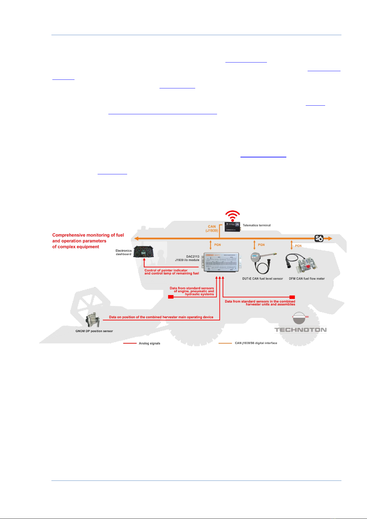
MasterCAN DAC2113 application
The availability of CAN j1939/S6 interface for MasterCAN DAC2113 enables to integrate the
Vehicle operation parameters received after the conversion of signals from standard and
additional analog sensors into the Telematics system using S6 Technology by means of the
cost-effective terminal with one CAN-input. The employment of MasterCAN DAC2113
together with DFM CAN fuel flow meters (up to 8 pcs.) and DUT-E CAN fuel level sensors
(up to 8 pcs.) is a convenient solution for comprehensive monitoring of fuel and
performance parameters for complex mobile equipment and fixed installations
(see figure 4).
Figure 4 —Example of MasterCAN DAC2113 application in the monitoring system using
CAN j1939/S6 to monitor fuel and operation parameters of complex equipment

General information and technical specifications / Delivery set
MasterCAN DAC J1939 i/o modules. Operation manual. Version 2.0
© Technoton, 2018 12
1.2 Delivery set
1MasterCAN DAC15 J1939 i/o module –1 pc.;
2Specification –1 pc.;
3Mounting kit (1 pc.) including:
a) fuse with holder 2 A (3 A) - 1 pc.;
b) cable tie - 20 pcs.;
c) contact pin - 8 pcs.;
d) molex 4 pin connector - 1 pc.;
e) molex 6 pin connector - 1 pc.;
f) molex 8 pin connector - 1 pc.;
g) power cable - 1 pc.;
h) wire - 17 pcs.;
i) S6 CW plug*- 2 pcs.
Figure 5 —MasterCAN DAC15 delivery set
*Contains the 120 Ohms inbuilt terminal resistor.
1
3 g
3 h
3 b
3 d
3 a
3 e
3 f
3 i
2
3 c

General information and technical specifications / Delivery set
MasterCAN DAC J1939 i/o modules. Operation manual. Version 2.0
© Technoton, 2018 13
1MasterCAN DAC2113 J1939 i/o module –1 pc.;
2Specification –1 pc.;
3Mounting kit (1 pc.) including:
a) fuse with holder 2 A (3 A) - 1 pc.;
b) S6 CW plug*- 2 pcs.;
c) cable tie - 25 pcs.;
d) contact pin - 8 pcs.;
e) molex 2 pin connector - 1 pc.;
f) molex 4 pin connector - 1 pc.;
g) molex 8 pin connector - 1 pc.;
h) molex 12 pin connector - 1 pc.;
i) molex 16 pin connector - 1 pc.;
j) self-tapping screw 6.3x25 - 4 pcs.;
k) screw M6x25 - 4 pcs.;
l) nut M6 - 4 pcs.;
m) washer 6 - 4 pcs.;
n) lock washer 6.65 - 4 pcs.;
o) S6 cable - 1 pc.;
p) wire - 42 pcs.
Figure 6 —MasterCAN 2113 delivery set
*Contains the 120 Ohms inbuilt terminal resistor.
1
3 o
3 p
3 b
3 e
3 d
3 a
3 c
2
3 f
3 g
3 h
3 i
3 j
3 k
3 l
3 m
3 n

General information and technical specifications / Exterior view and structure
MasterCAN DAC J1939 i/o modules. Operation manual. Version 2.0
© Technoton, 2018 14
1.3 Exterior view and structure
1–casing;
2–OUT connector (current/discrete 1/discrete 2/resistive outputs);
3–IN/OUT connector (analog voltage input/frequency
and analog voltage output/frequency/pulse);
4–POWER connector (Vehicle onboard circuit connection);
5–S6 connector (connection using CAN j1939/S6 interface);
6–red CAN LED indicator for data transmission via CAN j1939/S6 interface;
7–green POWER LED indicator to indicate the power supply
in the onboard circuit.
Figure 5 —MasterCAN DAC15 exterior view and design
1
5
3
2
4
6
7
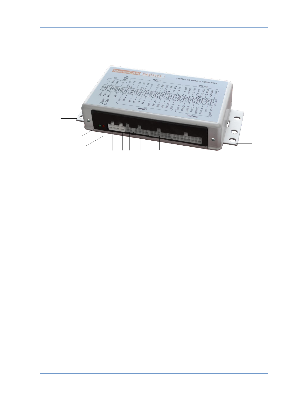
General information and technical specifications / Exterior view and structure
MasterCAN DAC J1939 i/o modules. Operation manual. Version 2.0
© Technoton, 2018 15
1–casing;
2–mounting bracket;
3–green PWR LED indicator;
4–red CAN LED indicator;
5–S6 connector (connection via CAN j1939/S6 interface);
6–5 V OUT connector (power supply connection (5 V, 30 mA)
for external devices);
7–Aconnector (resistive outputs (2 pcs.));
8–Bconnector (frequency (2 pcs.)/analog voltage (4 pcs.)/
current (1 pc.) inputs);
9–Cconnector (discrete inputs (12 pcs.));
10 –D connector (discrete (7 pcs.)/frequency (2 pcs.)/current (1 pc.)/
resistive (1 pc.)/analog voltage (2 pcs.) outputs).
Figure 8 —MasterCAN DAC2113 exterior view and design
1
2
2
3
4
5
6
7
8
9
10

General information and technical specifications / Principles and modes of operation
MasterCAN DAC J1939 i/o modules. Operation manual. Version 2.0
© Technoton, 2018 16
1.4 Principles and modes of operation
1) Mode of digital to analog CAN-gateway. After connection to CAN (J1939)
onboard bus or to CAN j1939/S6 Telematics interface MasterCAN DAC, in accordance
with its settings, receives digital data (PGN), sorts out parameters (SPN)containing
current data on fuel consumption and the Vehicle operation parameters, converts
SPN into analog signals, generates a physical signal in the selected output.
2) Mode of collector/converter of analog signals. When an analog signal is
transmitted, MasterCAN DAC, in accordance with its settings, converts the signal
received into digital data (SPN) which it transmits in generated messages (PGN) into
CAN/S6 Telematics interface.
3) Combined mode. MasterCAN DAC can simultaneously operate in Digital-analog
gateway and Analog signal collector-converter modes.

General information and technical specifications
/
Technical specifications
/
Main specifications
MasterCAN DAC J1939 i/o modules. Operation manual. Version 2.0
© Technoton, 2018 17
1.5 Technical specifications
1.5.1 Main specifications
Table 1 —MasterCAN DAC main specifications
Parameter, measurement units
Value
MasterCAN
DAC15
MasterCAN
DAC2113
Digital interface
CAN j1939/S6
Power supply range, V
9…45
Current consumption at 12/24 V, mA,
not more than
100/50
Ambient operation temperature range, C
-40…+85
Ingress protection rating
IP40
Overall dimensions, mm, not more than
see figure 9
see figure 10
Weight, kg, not more than
0.08
0.32

General information and technical specifications / Technical specifications / CAN j1939/S6 digital interface specifications and protocols
MasterCAN DAC J1939 i/o modules. Operation manual. Version 2.0
© Technoton, 2018 18
1.5.2 CAN j1939/S6 digital interface specifications and protocols
Specifications of CAN j1939/S6 MasterCAN DAC digital interface correspond to
S6 Technology. Data transfer protocols is based on SAE J1939 standard and meets its
requirements.
Configuration of MasterCAN DAC connection options via S6 Technology, as well as selection
of necessary PGN and SPN is performed via K-Line interface (ISO 14230) using
Servicse S6 MasterCAN software (can be downloaded from https://www.jv-technoton.com,
Software/Firmware).
MasterCAN DAC receives/transmits data automatically (default mode) or on request.
Baudrate can be selected from the following values: 100; 125; 250; 500; 1000 kbit/s
(default rate —250 kbit /s).
After the connection using S6 Technology, unique network addresses (SA) should be
specified for MasterCAN DAC15: 126 or 146 (126 by default), while for
MasterCAN DAC2113: 127 or 147 (127 by default).
Detailed information regarding the architecture of CAN j1939/S6 Telematics interface is
provided in its CAN j1939/S6 Operation manual.

General information and technical specifications / Technical specifications / Analogue signals specifications
MasterCAN DAC J1939 i/o modules. Operation manual. Version 2.0
© Technoton, 2018 19
1.5.3 Analog signals specifications
1) Analog signals of MasterCAN DAC15
Table 2 —Specifications of signals for MasterCAN DAC15 analog inputs
Signal type, measurement units
Value
Voltage, V
0.5…9
Frequency, kHz
0.01…10
Note —The input impedance of the analog input is at least 150 kOhm.
Table 3 —Specifications of signals for MasterCAN DAC15 analog outputs
Signal type, measurement units
Value
Voltage, V
0.5…9
Frequency, kHz
0.01…10
Pulse,
Amplitude, V;
Duration, ms.
0.5...9
40...250
Current, mA
4…20
Discrete, V
(upper branch (supplied U*PS))
level 0 —0
level 1 —U*PS
Discrete, V
(inverse, lower branch (supplied GND),
see annex B)
level 0 —10
(without connecting the load)
level 1 —0
Resistive, kOhm
0.015…50
*UPS –onboard circuit voltage.
Notes
1 The load current of the analog output should not exceed 40 mA.
2 The maximum current of the descrete outputs should not exceed 0.3 A.
3 The maximum load impedance for the current output is calculated according to the
formula: R L max =( U*PS - 5 V)/0.02 Ohms.

General information and technical specifications / Technical specifications / Analogue signals specifications
MasterCAN DAC J1939 i/o modules. Operation manual. Version 2.0
© Technoton, 2018 20
2) Analog signals of MasterCAN DAC2113
Table 4 —Specifications of signals for MasterCAN DAC2113 analog inputs
Signal type, measurement units
Value
Voltage, V
0.5…10
Frequency, kHz
(active level “low” (0…10 % U*PS))
0.01…10
Frequency, kHz
(active level “high”
(10 % U*PS…U*PS))
Resistive, kOhm
0.015…50
Current, mA
4…20
Discrete, V
(active level “low”)
level 0 —0…10 % U*PS
Discrete, V
(active level “high”)
level 1 —10 % U*PS…U*PS
*UPS –onboard circuit voltage.
Table 5 —Specifications of signals for MasterCAN DAC2113 analog outputs
Signal type, measurement units
Value
Voltage, V
0.5…10
Current, mA
4…20
Resistive, kOhm
0.015…50
Discrete, V
(upper branch (supplied U*PS))
level 0 —<5 %U*PS
level 1 —>80 %U*PS
Discrete, V
(inverse, lower branch (supplied GND)
level 0 —<5 %U*PS
level 1 —>80 %U*PS
Frequency, kHz
(amplitude 3.3 V)
0.01…10
Frequency, kHz (amplitude 5 V)
Frequency, kHz (amplitude 8 V)
Frequency, kHz (amplitude U*PS)
*UPS –onboard circuit voltage.
Notes
1 The maximum current of the descrete outputs should not exceed 0.5 A.
2 The maximum output current of the analog voltage should not exceed 50 mA.
3 The maximum load impedance for the current output is calculated according to the
formula R L max =( U*PS - 5 V)/0.02 Ohms.
The selection of the required type of analog input/output signals and configuration of their
values conversion into SPN is performed using Service S6 MasterCAN service software (the
current version can be downloaded at https://www.jv-technoton.com, Software/Firmware).
This manual suits for next models
1
Table of contents
Other Technoton Media Converter manuals


