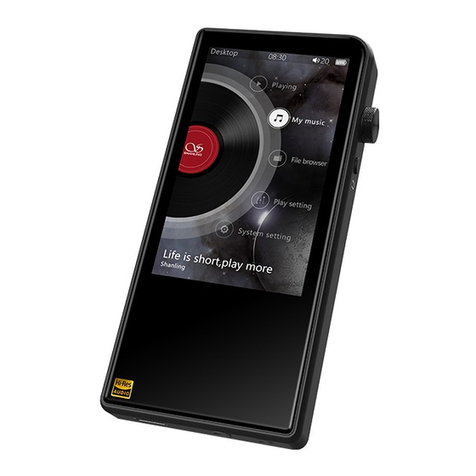
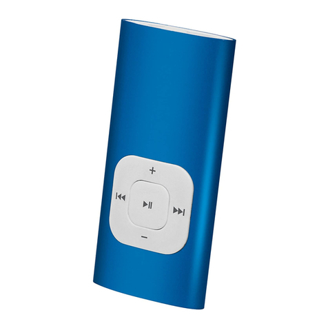
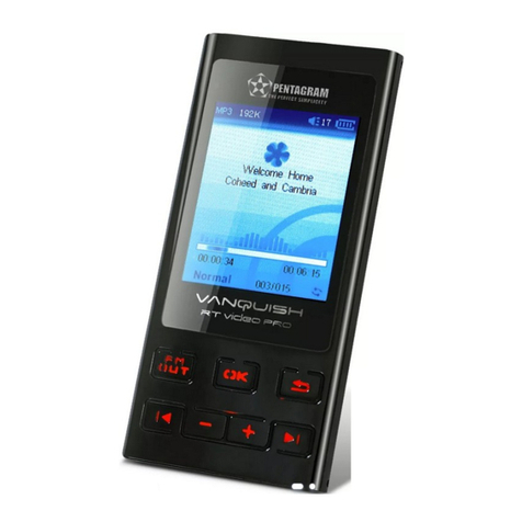
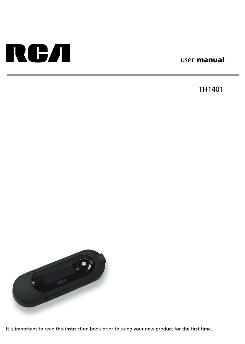
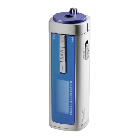
Teclast X21 User manual

service manual
X21(RU)

Catalog
Chapter One About Maintenance
1.1 Safety precautions
1.1.1 Precautions for antistatic
1.1.2 About placement position
1.2 Maintenance method
1.2.1 Visualized method
1.2.2 Electric resistance method
1.2.3 Voltage method
1.2.4 Current method
1.2.5 Cutting method
1.2.6 Element substitution method
1.2.7 Comparison method
1.3 Required device for maintenance
Chapter Two Functions and Operation Instructions
2.1 USAGE INTRODUCTION
2.1.1 FUNCTIONS AND FEATURES
2.1.2 BUTTONS AND JACKS ILLUSTRATION
2.1.3 MAIN MENU ILLUSTRATION
2.1.4 PLAYING INTERFACE ILLUSTRATION
2.1.6 RECORDING INTERFACE ILLUSTRATION
2.2 BASIC OPERATIONl
2.2.1 INSTALL USB DRIVE PROGRAM
2.2.2 INSTALL USB DRIVE PROGRAM
2.2.3 USE MOBILE STORAGE FUNCTION
2.2.4 DISCONNECT USB SAFELY
2.2.5 BROWSE/CANCEL FILE
2.2.6 PLAY MUSIC
2.2.7 PLAY MUSIC
2.1.5 TUNING INTERFACE ILLUSTRATION
1
1
1
1
1
1
2
2
2
2
2
2
3
4
4
4
4
5
5
6
6
6
6
6
6
6
7
7
7

2.2.8 A-B REPEAT FUNCTION
2.2.9 RECORDING
2.2.10 TUNING
2.2.11 TUNING
2.2.12 TUNING
2.3 SETTINGS
2.3.1 SETTINGS
2.3.2 PLAY MODE
2.3.3 EQ SELECT
2.3.4 SLEEP
2.3.5 3D
2.3.6 PLAYLIST
2.3.7 PLAYLIST
2.3.8 FM CHANNEL
2.3.9 SCREEN SAVE
2.3.10 ADVANCED
2.4 SPECIFICATION
Chapter Three Principle and Servicing
section One Principle of the Player
3.1.1 Function introduction and principle of the player
3.1.2 Block diagram
3.1.3 Introduction to IC used by the player
Section Two Unit Circuit Principle
3.2.1 FLASH circuit principle
3.2.2 FM module circuit
3.2.3 OLED module circuit
3.2.4 USB jack circuit
3.2.5 Button circuit
3.2.6 Charge management circuit
3.2.7 Low voltage detecting circuit
3.2.8 Battery protection circuit
3.2.9 Power management module
3.2.10 Headphone jack circuit
3.2.11 Reset circuit
7
7
8
8
8
8
8
9
9
9
9
9
10
10
10
10
11
12
12
12
12
13
14
14
14
16
17
17
18
19
19
20
22
22
23

3.2.12 ON/OFF control circuit
3.2.13 MIC circuit
Section Three Servicing Cases
3.3.1 Servicing cases
3.3.2 Troubleshooting flow chart
Section Four Servicing Parameters
3.4.1 Key point waveform diagram
3.4.2 Key point voltage list
Section Five Function Introduction to IC
3.5.1 Function introduction to PNX0101
3.5.2 Function introduction to G690
3.5.3 Function introduction to PQ1X281
3.5.4 Function introduction to TC58512FT
3.5.5 Function introduction to SI1912DL
3.5.6 Function introduction to LM2703
3.5.7 TPS79301
3.5.8 Function introduction to TPS62200
3.5.9 Function introduction to ISL6294
3.5.10 Function introduction to S80829
3.5.11 Function introduction to TEA5767HN
Chapter Four Disassembly and Assembly Process
4.1 Whole set
4.1.1 Disassembly process of the whole set
4.1.2 Assembly process of the whole set
4.2 OLED display screen
4.2.1 OLED disassembly process
4.2.2 OLED assembly process
4.3 Li battery
4.3.1 Li battery disassembly process
4.3.2 Li battery assembly process
4.4 FM tuning board
4.4.1 FM tuning board disassembly process
4.4.2 FM tuning board assembly process
23
23
25
25
30
36
36
43
44
44
48
49
49
50
50
51
51
52
53
53
55
55
55
57
58
58
58
59
59
59
60
60
60

Chapter Cinque PCB board & Circuit diagram
Section One PCB board
Section Two circuit diagram
Chapter six BOM List
61
61
62
66

Chapter One About Maintenance
1.1 Safety precautions
1.1.1 Precautions for antistatic
Movement and friction will both bring static electricity which causes serious damages to integrated
IC. Though static charge is little, when a limited quantity of electric charge is added to large-
scaleintegrated IC, as the capacitance is very small in the meantime, now the integrated IC is very much
easy to be struck through by static electricity or the performance will decrease. Thus static electricity
prevention is of extraordinary importance. The following are several measures to prevent static
electricity:
1. Use a piece of electric conduction metal with the length of about 2 metres to insert into the earth,
and Fetch the lead wire from the top of the surplus metal and connect to the required static electricity
device. The length and depth of the metal embedded under the earth should be determined according to
the wettability of the local soil. For humid places, it may be shorter, and longer and deeper for dry places.
If possible, it can be distributed and layed in terms of “#” shape.
2. On operating table-board, the antistatic table cushion should be covered and grounded.
3. All devices and equipments should be placed on the antistatic table cushion and grounded.
4. Maintenance personnel should wear antistatic wrist ring which should be grounded.
5. Places around the operating position should also be covered with electric conduction cushion or
Painted with antistatic paint.
1.1.2 About placement position
1. Audio power amplifier cannot be installed in places with high temperature and humidity.
2. Positions for placement should be stable and secure.
1.2 Maintenance method
1.2.1 Visualized method
Directly view whether abnormalities of collision, lack of element, joint welding, shedding welding,
rosin joint, copper foil turning up, lead wire disconnection and elements burning up among pins of
- 1 -

- 2 -
Elements appear. Check power supply of the machine and then use hands to touch the casing of part of
elements and check whether they are hot to judge the trouble spot. You should pay more attention when
using this method to check in high voltage parts.
1.2.2 Electric resistance method
Set the multimeter in resistance position and test whether the numerical value of resistance of each
point in the circuit has difference from the normal value to judge the trouble spot. But in the circuit the
tested numerical value of resistance is not accurate, and the tested numerical value of integrated IC's
pins can only be used for reference, so the elements should be broken down for test.
1.2.3 Voltage method
Voltage method is relatively convenient, quick and accurate. Set the multimeter in voltage position
and test power supply voltage of the player and voltage of a certain point to judge the trouble spot
according to the tested voltage variation.
1.2.4 Current method
Set the multimeter in current position and test current of the player of a certain point to judge the
trouble spot. But when testing in current method, the multimeter should be series connected in the
circuit, which makes this method too trivial and troublesome, so it is less frequently used in reality.
1.2.5 Cutting method
Cutting method should be combined with electric resistance method and voltage method to use.
This method is mainly used in phenomena of short circuit and current leakage of the circuit. When
cutting the input terminal voltage of a certain level, if voltage of the player rises again, it means that the
trouble lies in this level.
1.2.6 Element substitution method
When some elements cannot be judged good or bad, substitution method may de adopted directly.
1.2.7 Comparison method
A same good PC board is usually used to test the correct voltage and waveform. Compared these
data with those tested through fault PC board, the cause of troubles may be found.
Through the above maintenance method, theoretical knowledge and maintenance experience, all
difficulties and troubles will be readily solved.

1.3 Required device for maintenance
Audio Generator
Digital oscillograph ( 100MHE)
SMD rework station
Multimeter
Soldering iron
Pointed-month pincers
Cutting nippers
Forceps
Electric screw driver
Terminals connecting cord
Headphone
Microphone
- 3 -

Chapter Two
Functions and Operation Instructions
2.1 USAGE INTRODUCTION
2.1.1 FUNCTIONS AND FEATURES
Adopt famous Philips PNX0101 audio decode chip, special for Hi-Fi MP3 player, forcefully
making up audio signal loss when compressing MP3 to revert audio signal better.
# Sennheiser headphone MX400)
Build high-quality musical effect.
# Support 3D surround stereo sound effect, 9 EQ modes
You may taste heart quaking bass and vivid surround stereo sound effect.
# Play MP3/WMA/WAV files
Support 16kbps - 320kbps MP3 file and 8kbps 192kbps WMA file.
# Mobile storage function
Capable of downloading files from Windows resource manager.
# FM tuning function
Auto scanning and auto/manual memory function may listen to FM radio station programs
more easily.And you may record FM program into WAV files directly.
# Voice recording function
May be used to record in class, meeting and interview.
# USB 2.0 transmission (full speed)
USB2.0 full speed data transmission.
# Support firmware upgrading function
Support upgrading function. You may add new function to the built-in program of this player
conveniently.
2.1.2 BUTTONS AND JACKS ILLUSTRATION
# Philips PNX0101audio decode chip
LifeVibesTM
M
5
4
23
8
76
1.1
1.2
1.3
1.1 # Press for long in any case
# Press in tuning mode
# Press in recording mode
# Press when operating in menu
enter main menu
switch in PRESET and SCAN mode
exit recording
not save the setup and return to the previous menu
- 4 -

1.3
1.2 # Press in playback mode
# Press for long in playback mode
# Press in tuning Preset mode
# Press in tuning SCAN mode
# Press for long in tuning Preset mode
# Press for long in tuning SCAN mode
# Menu mode
# Press in power-off mode
# Press for long in power-on mode
# Press in playback mode
# Press in recording mode
# Press in tuning mode
# Press in menu mode
# Press for long in menu mode
# Press in playback mode
# Press for long when playing music file
(non recording file)
# Press in browsing file mode
# Press for long in tuning mode
# Press in Play and tune mode
# Press in
the next/previous track
fast forward/backward
select channel
manual scanning
full auto scanning
automanual scanning
move cursor or set item
power on
power off
pause playing
pause recording
pause (mute)
enter the selected item or
confirm the setup
enter recording mode
A-B repeat
switch
sound effect
delete file
Start FM recording
adjust volume
adjust dB value
2
3
45
HOLD button: Push towards arrow to lock buttons; and push toward the opposite direction to
unlock.
Headphone jack
USB jack
2.1.3 MAIN MENU ILLUSTRATION
6
7
8
# My music
Memorize music file.
# My Voice
Memorize microphone recording file,
such as meeting, classroom and
interview recording, etc.
# Resume Play
Select "Resume Play" and the player
begins to play from the position that
music stopped playing last time.
# REC
Select "REC"to enter recording
mode
# FM Radio
Select " FM Radio"to enter radio mode.
# System Setup
Select " System Setup" to set system items.
# System Setup
Select " System Setup" to set system items.
2.1.4 PLAYING INTERFACE ILLUSTRATION
1Play State
Sound effect mode
Playback mode
2
3
4Repeat state
Battery capacity
Song name and Singer
5
6
7Time that has been played
Number of tracks
Spectrum display
8
9
- 5 -

13
4
2
2.1.5 TUNING INTERFACE
ILLUSTRATION
1PRESET mode (normal receiving)
Frequency of the current radio station
Battery capacity
Frequency bar
PRESET channel display
SCAN mode (scanning)
2
3
4
5
6
1
2
34
5
2.1.6 RECORDING INTERFACE
ILLUSTRATION
Name of recorded file
Battery capacity
Time that has been recorded
The left recordable time
Recording state
1
2
3
4
5
As for the name of recorded file
"V001.WAV": 001 is serial number of the current
recorded track and arranged according to
sequence; WAV is file format after recording
2.2 BASIC OPERATION
2.2.1 INSTALL USB DRIVE
PROGRAM
If your computer is Windows 98, you must
install drive program if you want to use the
mobile storage function of MP3 player in
computer.
1. Place USB drive disc into CD-ROM driver of
computer.
2. Connect MP3 player to computer will
automatically indicate that
new firmware device has been found, and run
the installation guide, shown as the following
figure.
You only need to find the drive nformation file
on disc according to prompt information to
finish the installation of drive program.
3. After installation finishes, restart the computer
and you may use the mobile storage function
normally.
Shown as the following figure:
2.2.2 INSTALL USB DRIVE
PROGRAM
2.2.3 USE MOBILE STORAGE
FUNCTION
This player can be used as mobile storage
in Windows ME/2000/XP operating system. In
Windows 98SE and Mac operating system, drive
program must be installed firstly and then used
as mobile storage. Connect Mp3 PLAYER and
computer with USB transmission line. After the
bottom right comer of desktop appears” “
symbol, the mobile storage function of Mp3
PLAYER may be used normally.
NOTE:
# To avoid abnormality of the player appears,
you are suggested to power off firstly before
connecting use USB transmission line to
connect Mp3 PLAYER, then connect computer.
# In Windows 98 system, there is no” “ symbol.
2.2.4 DISCONNECT USB SAFELY
After operation finishes, click” “ symbol
on bottom right corner of Windows desktop with
right button of mouse, and disconnect USB
safely according to the computer prompt.
- 6 -

M
/
/
M
PRESS
FOR LONG
PRESS
PRESS
PRESS
PRESS
2.2.5 BROWSE/CANCEL FILE
# BROWSE FILE
In any case, press button for long to enter
"Main Menu". Music fileand recording file are
separately saved in the first two items of main
menu, "My Music" and "My Voice". Press
button to select upward or downward and then
press button to enter files browsing .
# CANCEL FILE
When browsing files, press button and
the cancel dialogue box will pop up. Press
button to select "YES" and then press button
to cancel the file. Select "NO" to exit.
/
PRESS
2.2.6 PLAY MUSIC
# PLAY MUSIC
press button to select song In "My
Music". Press button or select playback in
main menu to begin playing music, meanwhile
the playback interface displays.
# PAUSE PLAYING MUSIC
When playing, press button to switch to
pause state. Press button again to continue
playing.
# NEXT and PREV
When playing, pressing button may skip
to the next track to play. If playback time of the
current track is less than 5 seconds, pressing
button may skip to the previous track to play,
otherwise the current track will be played again if
playback time is more than 5 seconds.
2.2.7 PLAY MUSIC
# FF and FB
When playing, pressing button for long
may realize fast forward.
PRESS
FOR LONG
PRESS
FOR LONG
When playing, pressing button for long
may realize fast backward.
CAUTION:
Fast forward and fast backward operation
are only for the current track. After fast
backward/forward to the beginning/ending of
track, it switches into normal playback
automatically.
CAUTION:
/
2.2.8 PLAY MUSIC
When playing or tuning, pressing button
or for long may adjust volume. The display of
adjusting volume in music playback interface is
shown as follows:
CAUTION:
2.2.9 A-B REPEAT FUNCTION
When playing, if you want to listen to a
certain segment repeatedly, please use A-B
repeat function.Press button for the first time
to select the beginning point that you desire
to repeat play and screen displays " ";press it
for the second time to select the ending point
that you desire to repeat play and screen
displays " “, and system begins to repeat play
between A-B segment. Press button for the
third time to cancel repeat and continue to play.
# Music playback will be paused when browsing
file.
# In some operating system (such as complex
font Windows), the operation of copying
lyrics/song file and changing song's name may
probably lead to incorrect display. When
playing WMA songs of VBR , pressing buttons
may probably has slow response or has no
lyrics display. When playing some non
standard songs or songs with special format,
noise may probably occur.
M
M
PRESS
FOR LONG
PRESS
PRESS PRESS PRESS
2.2.10 RECORDING
When recording, press button to pause
and press button for long to exit recording
and then make files.
- 7 -

CAUTION:
# To avoid sudden power-off when
recording, you cannot record when in low battery
and when disc is fully written. If you are
recording, it indicates "DISC FULL" and exits
recording.
# When recording with microphone, if you press
buttons and the sound of pressing may
probably be recorded.
2.2.11 TUNING
# ENTER TUNING MODE
Select "FM Radio" in main menu and press
button to listen to radio.
# EXIT TUNING MODE
When listening to radio, press button for
long to return to main menu.
# PRESET/SCAN MODE SWITCH
When listening to radio, press button to
M
M
M
PRESS
1. PRESET mode
# ADJUST CHANNEL
Press button to enter the next channel,
and press button to enter the previous
channel.
2.2.12 TUNING
FULL AUTO SCANNING
In PRESET mode, press button for long to
begin full auto scanning. All
scanned radio stations will be saved in PRESET
channel automatically.
/
PRESS
FOR LONG
2. SCAN MODE
# MANUAL/AUTOMANUAL SCANNING
Press button to increase 0.1MHz each
time; and press button to decrease 0.1MHz
each time. Press button to save radio station.
Press button for long to increase
frequency continuously and stop until radio
station has been searched. Press button to
save radio station.
Press button for long to decrease
frequency continuously and stop until radio
station has been searched. Press button to
save radio station.
M
/
M
PRESS
2.2.13 TUNING
# SAVE RADIO STATION
Select channel in Preset mode firstly, and
then switch to SCAN mode to adjust frequency
(manually or automanually). After scanning
desired frequency, press buttonto save
into the current PRESET channel.
CAUTION:
In the course of full auto/automanual
scanning, press or button to stop
scanning.
# FM RECORDING
In tuning mode, press button for long to
enter FM recording. Press button to stop
recording and make recording fil . FM recording
makes WAV format file.
2.3 SETTINGS
2.3.1 SETTINGS
# Play Mode
Normal
Shuffle
Playlist
Intro
REP One
REP ALL
REP DIR
# EQ Select
Normal
3D
PURE
POP
Clas
Jazz
Rock
Dbass
Disco
My EQ
# Sleep
Disable-
120Min
# 3D Setup
BassBoost
ConcertSound
# Playlist
Browse
Edit
Delete
# FM Channel
Auto
Mono
# Screen Save
Disable - 5Min
- 8 -

# Advanced
My EQ
REC Set
Format
Load Default
System Info
Language
2.3.2 PLAY MODE
The playback symbol displays on playback
interface is shown as follows:
Play according to track sequence.
random play any one track.
play the track edited in program list.
browse play each track for 10 seconds.
repeat play single track.
repeat play all tracks.
repeat play all tracks in this Folder.
CAUTION:
# Play mode is defaulted to "Normal" each time
when power on.
# Files in "My Voice" only support sequence
playback.
# When playing files in "My Voice", there is no
"Play mode" item.
2.3.3 EQ SELECT
Press button to enter "EQ SELECT", and
then use to move cursor, shown
as follows:
M
/
PRESS
The corresponding icons of each EQ mode
in playback mode are shown as follows:
NORMAL
3D
PURE
POP
CLAS
JAZZ
ROCK
DBASS
DISCO
My EQ
Select "3D", and correspond with 3D that
you have preset in "MAIN MENU->SYSTEM
SETUP->3D SETUP. If you have not set it, it is
default value.Select "MY EQ", and correspond
with the sound effect that you have preset in
"MAIN MENU->SYSTEM SETUP->ADVANCED".
If you have not set it, it defaults "MY EQ" to
NORMAL" sound effect.
When the cursor moves to a certain sound
effect mode, the sound effect mode played by
Mp3 player will switch to that in the cursor for the
moment to facilitate you to select your desired
sound effect mode. Press button to confirm
this sound effect mode.
CAUTION:
When playing files in "REC", there is no "EQ
Select " item.
2.3.4 SLEEP
Press button to adjust the timing
power-off time. After setup finishes, press
button to save and then exit, and press button
not to save and then exit. If timing power off time
is 15 minutes, after 15 minutes, MP3 PLAYER
will power off automatically.
/
M
PRESS
PRESS
PRESS
PRESS
CAUTION:
# It is defaulted to be invalid each time when
power on.
2.3.5 3D
In this menu, "3D “ may be adjusted.
BassBoost can strengthen bass effect; and
concert can build classical sound field effect. At
the same time of confirming clearness,
strengthen hearing feeling. Through adjustment,
you may feel live and vivid sound field
effect no matter where you are.
# Timing power-on time is a rough time, and may
have difference.
PRESS
PRESS PRESS PRESS
2.3.6 PLAYLIST
# Browse
Select "Browse" , and you may check how
many songs have been program-med into
playlist.When browsing playlist. Pressing
button may begin playing.
Note: Playback will be paused when in
"Browse" or "Edit" list.
# Edit
- 9 -

PRESS
As in the above illustration, enter "Edit" and
browse files. The icon before songs in the
playlist is " “. Select a song not in the playlist
and press button to add it intothe list. Select a
song in the playlist ,and press button to cancel
it from the playlist,You can add 15 songs into the
playlist at most.
# Delete
Select "Delete". After dialogue box pops up,
select "YES", and press button to
confirm and the playlist is cleared.
PRESS
/
M
PRESS
PRESS
2.3.7 PLAYLIST
NOTE:
# If the operation of adding or cancelling music
files is detected, MP3 PLAYER will clear
the playlist automatically.
2.3.8 FM CHANNEL
# You cannot enter "Edit list" and "Clear list"
when in program playback.
You can select the FM channel in settings.
When select Auto, it changes the channel
automatically when in tunning mode. When
select Mono, it tunes at Mono channel all the
time.
2.3.9 SCREEN SAVE
Press button to adjust the screen
saver time. After setup finishes, press button
to save and then exit, and press button not to
save and then exit. If the screen saver setup time
is 3 minutes and no operation occurs within 3
minutes, Mp3 PLAYER will enter screen saver
state automatically.
PRESS
PRESS
2.3.10 ADVANCED
Advanced items include some other system
internal setup, such as user sound effect setup,
default setup and system information.
# My EQ
In
“My EQ" interface, you may see the decibel
(dB) of each frequency.
If you want to adjust the decibel of mediant
(1kHz), operate according to the below
illustration.
M
PRESS
PRESS
PRESS
When adjusting width, take 3dB as a step
and the max adjustable range is 15dB. After
setup finishes, press button to confirm and
exit, and press button to exit with the original
setup not being changed.
# REC Set
Here to set the recording quality ,The
recording quality is higher, the sound quality is
better and the used space is more. Three kinds
of recording quality adopt IMA-ADPCM
format coding.
M
PRESS
PRESS
/
PRESS
PRESS
# Format
Enter this menu, and you may format hard
disk. When dialogue box pops up, press
button to move cursor to “YES”,and then press
button to confirm to finish formatting operation.
# Load Default
If you want to restore MP3 PLAYER to
factory setup state (data and song files cannot
be cancelled), you may select “ Load Default ”.
After dialogue box pops up, select “YES” ,
press button to confirm and then exit to restore
to default state. Select “NO” or press button to
cancel.
CAUTION:
Estore to "Default" state is effective only
when power on again.
# System Info
You may find information of firmware
version, total disc capacity and left disc capacity.
- 10 -

PRESS
M
In system information menu, press button to
return to the previous menu.
CAUTION:
Because firmware will use some space, the
displayed content capacity may probably be
different from the actual capacity.
# Language
Russian and English are supported.
PRESS
# Upgrade
Download the latest firmware upgrading file
from BBK website firstly, such as "BBK X21RU.
ebn" and "X21RU_Resource.bin", copy the two
files into MP3 PLAYER at the same time, and
then power on again. Find "Upgrade" item in
"ADVANCED" of "SETTINGS", and pressing
button may start upgrading.
NOTE:
# Only MP3 player detects that there is
upgrading file in system when this player
power on, "Upgrade" menu will appear in
"ADVANCED" item.
# Make sure MP3 PLAYER has enough quantity
of electric charge before upgrading.
# To ensure successful firmware upgrading, do
not power off during the course of upgrading.
# Upgrading will last about 10 seconds or more,
please try your best not to operate any buttons
during this course.
# After firmware upgrading finishes, some
function or interface may probably be different
from user manual, so please take real object
as standard.
After upgrading finishes, MP3 PLAYER will
power on again.
2.4 SPECIFICATION
Model X21
Audio dicode chip Philips PNX0101
Continuous playback time The longest time is about 10 hours
Dimensions/weight 57mm×45mm×14mm about 30.7g
Audio SNR 90dB
Headphone out 9mW+9mW(32ohm im pedance)
Frequency range 18Hz~20kHz
FM tuning rang 87.5MHz~108MHz
Working temperature 0~40
Files supported MPEG 1/2 Layer 3(16kbps~320kbps),WMA(8kbps~192kbps),WAV
- 11 -

section One Principle of the Player
3.1.1 Function introduction and principle of the player
X21 (RU) portable MP3 player is composed of the following functional modules:
# MP3 main decode chip: main chip adopts PNX0101 decode chip of Philips Company, PNX0101 is
the professional MP3 decode IC of Philips Company, with ARM and DSP integrated inside. The
advantages are good sound quality and low power consumption.
# Power management module: composed of TPS79301, TPS62200 and PQ1X28 and responsible
for the power supply of each part of MP3.
# USB module: USB jack, data exchange, and charge function.
# Lithium battery module: power supply of the player.
# Memory module: data storage of the player.
# OLED module: display of the working state of the player.
# Headphone output: audio output.
# MIC: external audio input, which fulfills recording function.
# Tuningmodle: FM tuning.
3.1.2 Block diagram
Block diagram is shown in the figure 3.2.1.1:
Chapter Three Principle and Servicing
Figure 3.1.2.1 Blockdiagram of X21(RU)
USB power
Charger power
USB jack
Power
management
module
LDO
TPS79301
DC-DC
TPS62200
LDO
PQ1X28
Low voltage detect
S80821
Reset IC
G690L263T
DC-DC
LMS2703
Button and
switch control
circuit
12M crystal
oscillator
Lithium battery
module
Charge
management
ISL6294
FLASH MEMORY FM module TEA5767
MIC
Headphone
output
OLED module
PNX0101
5V
3.6V~4.2V
12.1V
3.3V
1.8V
2.8V
- 12 -

3.1.3 Introduction to IC used by the player
Introduction to IC used by X21 (RU ) is shown in the following figure:
PCB board Location IC model Function
U1 TPS79301 Provide 3.3V voltage
U2 G690L263T System reset
U3 TPS62200 Provide 1.8V voltage
U4 ISL6294 Charge management
U5 S80829 Low voltage detect
U6 Philips PNX0101 MP3 decode
U7 PQ1X28 Provide 2.8V voltage
U8 TC58512FT Flash Memory
U9 SI912DL Headphone mute
Tuning board U1 TEA5767HN Tuning module
Mian board
- 13 -

R1
100K
FLASH3V3
/WP
FLASH3V3
D_GND D_GND
D_GND
R2
100K
C1
104
C2
104
U1 TC58512FT
NC
1
NC
2
NC
3
NC
4
NC
5
GND
6
RY/BY
7
RE
8
CE
9
NC
10
NC
11
Vcc
12
Vss
13
NC
14
NC
15
CLE
16
ALE
17
WE
18
WP
19
NC
20
NC
21
NC
22
NC
23
NC
24
NC 48
NC 47
NC 46
NC 45
I/O8 44
I/O7 43
I/O6 42
I/O5 41
NC 40
NC 39
NC 38
Vcc 37
Vss 36
NC 35
NC 34
NC 33
I/O4 32
I/O3 31
I/O2 30
I/O1 29
NC 28
NC 27
NC 26
NC 25
MPMC_AD7
MPMC_AD5
MPMC_AD6
MPMC_AD2
MPMC_AD0
MPMC_AD1
MPMC_AD3
MPMC_AD4
FLASH3V3
/RE
/CE
/WE
CLE
ALE
Figure 3.2.1.1 Flash circuit schematic diagram
2. Working principle: Flash Memory is the storage unit of the player and all Mp3 and waveform files
must be saved in FLASH. Flash module is composed of FLASH chip TC58512FT and peripheral circuit,
which fulfills the read, write and cancel working of internal files. In whic
ull-up resistor of /CE, R40 is pull-down resistor of /WP, Vcc is power supply pin of
FLASH, /CE is chip selection signal, VCC33 provides 3.3V voltage and FLASH begins to work. /RE, /WE
are effective read and effective write signal end respectively to control read and write function of FLASH.
I/O1 I/O8 is 8 data lines to fulfill the exchanges of FLASH and external data.
3.2.2 FM module circuit
1. FM module circuit schematic diagram is shown in the figure 3.2.2.1:
2. Working principle: FM module is composed of microwave digital tuning IC TEA5767HN produced
by Philips Company and the peripheral circuit, in which, L17, C54, C55 is the power supply filtering
circuit of FM module that provides IC with the pure voltage with typical value 2.8V. Cn1 is the socket
between FM module and main board.
h, 601 magnetic L15, 104
capacitor C45 and C46 compose FLASH power filtering circuit and provide FLASH with pure 3.3V
voltage. R38 is p
3.2.1 FLASH circuit principle
1. FLASH circuit schematic diagram is shown in the following figure 3.2.1.1:
Section Two Unit Circuit Principle
- 14 -

C1 101
FM_OUTL
XT1
32.768KHz
C17
223
C18
102
R7
22R
O603CS
D-GND
SGND
NECTAR-IO603CS
IIC_SCL 2
FM_ANT
SGND
SGND
SGND
SGND
SGND
SGND
SGND SGND SGND
SGND
D-GND
D-GND D-GND
D-GND
FM_ANT3
FM_3V3
FM_3V3
FM_3V3
FM_3V3
D2
BB202
D1
BB202
C13
104/X5R/0402
R5
100K
R6
33K
C15
22PF
C14
102
L3
33nH 2%
L1
120nH/ 2%
L2
33nH 2%
C19
104/X5R/0402
FM_OUTL
FM_OUTR
dandu
FM_OUTR
IIC_SDA 2
C10
393
C9 333
C12 333
C6 473
C7 473
C8 473
C16
223
C11 103
U1
TEA5767HN
N.C
1
N.C40
CPOP
2
VCOT1
3
VCOT2
4
VCOVCC
5
DGND
6
DVCC
7
DATA
8
CLOCK
9
N.C
10
W/R
11
BUSM
12
BUSEN
13
SWP1
14
SWP2
15
XTAL1
16
XTAL2
17
PDLF
18
PHLF
19
N.C
20
N.C 21
LAVO 22
RAVO 23
TMUTE 24
MPXO 25
VREF 26
TCIFC 27
DIFL1 28
DIFL2 29
N.C 30
N.C31
IFGAI32
AGND33
AVCC34
RFI135
RFGND36
RFI237
TCAGC38
LOOPSW39
R1
10R
C5
475/X5R/0603
R2 18K 1%
C4
47PF
C2 27PF
C3
472
R3
10K
R4
22R
Figure 3.2.2.1 FM module circuit schematic diagram
C1, C2, C3, C4, L1 is the antenna input matching circuit of FM module; variable capacitance diode
D1, D2 and winding inductor is the frequence selection tuning circuit in FM module. The control of FM
adopts IIC bus control means, 9 and 10 of TEA5767 are two control input ends.
- 15 -
Table of contents
