manuals.online logo
Brands
  1. Home
  2. •
  3. Brands
  4. •
  5. Tecnocontrol
  6. •
  7. Gas Detector
  8. •
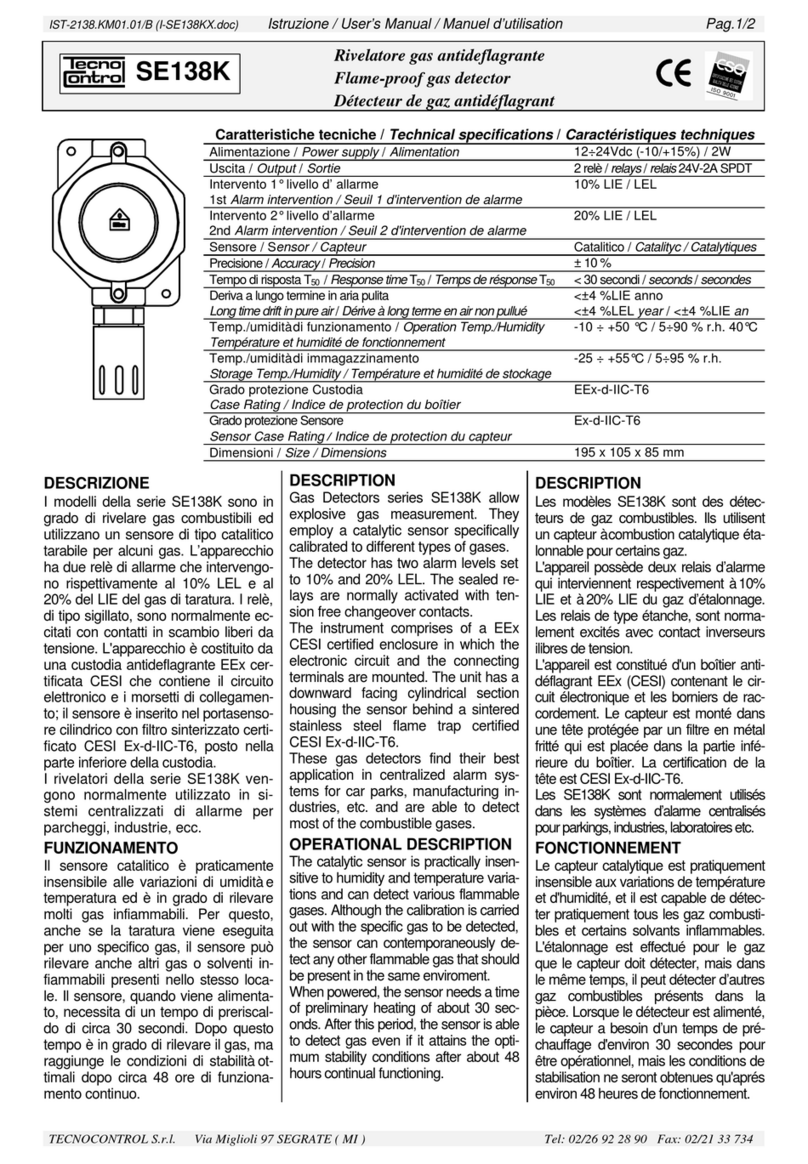
  9. Tecnocontrol SE148K User manual

Tecnocontrol SE148K User manual

IST-2148.KX01.01/B I-SE148K Pag.1/1
Centralina gas
Gas detector
Centrale détection de gaz
TECNOCONTROL S.p.a: Via Miglioli 97 SEGRATE ( MI ) Tel: 02/26922890 Fax: 02/2133734
SE148K
Tecnocontrol SE148K
GAS DETECTOR RESET
%LEL
01020
FAULT ON ALARM1 ALARM2
TEST
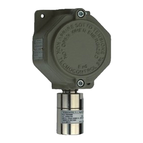
Sensori collegabili all’SE148K
Sensors which can be connected to the SE148K
Sondes raccordables au SE148K
Modello
Model
Modéle
Caratteristiche
Features
Caractéristiques
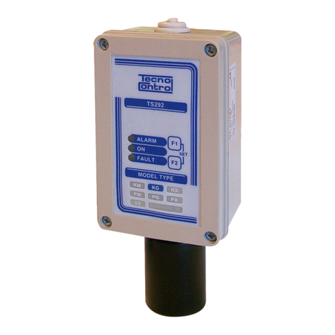
TS292KM Metano / Methane - IP65
TS292KG GPL / LPG - IP65
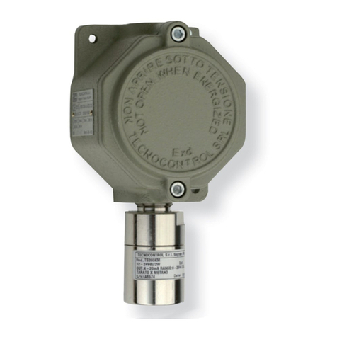
TS293KM Metano / Methane
Antideflagrante / Flameproof / Antidéflagrante
TS293KG GPL / LPG
Antideflagrante / Flameproof / Antidéflagrante
Caratteristiche tecniche / Technical specifications / Specifications techniques
Alimentazione con sensore / Power supply with sensor / Alimentation avec sonde 230Vac (-15/+10%) 50Hz / 4VA
12Vdc (-10/+15%) 2W (±10%)
Temp./umidità di funzionamento / Operation Temp./Humidity / Température et hu-
midité de fonctionnement
-10 ÷ +50 °C / 5÷90 % r.h. 40°C
Temp./umidità di immagazzinamento / Storage Temp./Humidity / Température et
humidité de stockage
-25 ÷ +55°C / 5÷95 % r.h.
Intervento allarme / Alarm intervention / Seuil d'intervention de alarme 10% LIE / LEL
Intervento blocco / Lock intervention / Seuil d'intervention de blocage 20% LIE / LEL
Contatti relè / Contacts rating / Contact relais 230Vac 3A SPDT
Dimensioni / Size / Dimensions 160 x 115 x 80 mm) / IP54
Sensore esterno / Remote sensor / Sonde extérieure Catalitico / Catalityc / Catalytiques
Conforme alle norme/ In compliance with rule / Conforme aux normes EN 50054-50057
DESCRIZIONE
L'SE148K è una centralina per mon-
taggio a parete con un sensore remoto
di tipo catalitico per gas infiammabili.
Possono essere collegati sia i sensori
tarati per Metano che per GPL. Il grado
di protezione dell'apparecchio è IP54.
I'SE148K viene normalmente alimenta-
to da rete ma può essere collegato ad
una alimentazione esterna a 12Vcc.
Sulla targa frontale è visibile la barra
Led che indica lo stato di funzionamen-
to e la concentrazione di gas rilevata
dal sensore.
La centralina è dotata di due livelli di
allarme con uscite a relè di tipo sigillato
normalmente eccitati con contatti in
scambio liberi da tensione.
In Fig.1 è illustrato un tipico
collegamento da rete con sirena di
allarme ed elettrovalvola normalmente
chiusa.
FUNZIONAMENTO
Quando la concentrazione di Gas rag-
giunge il 10% del LIE, cui corrisponde
l'accensione del secondo Led rosso,
interviene il primo relè "ALARM1" che
viene normalmente utilizzato come
preallarme per comandare una sirena
(Mod.SE301A).
DESCRIPTION
The SE148K is a gas detector to be
wall-mounted. It is rated to IP54. It has
one remote catalytic sensor for flam-
able gases calibrated for Methane or
LPG.
The SE148K is normally 230 AC pow-
ered, but can also be connected to a
12Vdc external power supply.
On the front plate the LED bar shows
both the working condition and the gas
concentration detected by the sensor.
The instrument is supplied with two
alarm levels with sealed-type normally-
activated relays outputs (tension-free
change over contacts).
Fig. 1 shows a typical mains supply wir-
ing diagram with alarm siren and nor-
mally closed solenoid valve.
OPERATIONAL DESCRIPTION
When the gas concentration attains
10% LEL (illumination of the 2nd red
LED), the first "ALARM 1" relay will ac-
tivate. This relay is normally used as a
prealarm for the controlling of a siren
(model SE301A).
When the Gas concentration attains
20% LEL, the 3rd red LED will illumi-
nate and after 30 seconds the second
"ALARM 2" relay will activate.
DESCRIPTION
Le SE148K est une centrale de détec-
tion de gaz pour montage aux mur et
pouvant recevoir 1 sonde à distance de
type catalytique pour gaz inflammables,
tarées pour le méthane ou pour le GPL
avec protection boîtier IP65. L'indice de
protection de la centrale est IP54.
Le SE148K est alimenté normalement
en 230Vca. il peut être raccordé à une
alimentation extérieure 12Vcc.
Sur la face avant de la centrale l'on dis-
tingue le barregraphe indiquant l'état de
fonctionnement ainsi que la concentra-
tion de gaz détectée par le capteur.
L'appareil est doté de 2 seuils d'alarme
avec sorties sur relais de type étanche
fonctionnant normalement excités avec
contacts inverseurs libres de tension
(sécurité positive).
En figure1, un exemple de raccorde-
ment sur secteur avec sirène d'alarme
et électovanne normalement fermée.
FONCTIONNEMENT
Lorsque la concentration de gaz rejoint
10% de la LIE à laquelle correspond
l'allumage de la 2ème LED rouge, le
1er relais intervient en se déséxcitant
(ALARM1).
IST-2148.KX01.01/B I-SE148K Pag.2/2
Quando la concentrazione di Gas rag-
giunge il 20%LIE si illumina il 3° Led
rosso e dopo 30 secondi si attiva il se-
condo relè "ALARM 2" che è utilizzato
per il blocco del gas tramite elettroval-
vola e/o l'interruzione dell'energia elet-
trica.
Quando si attiva il relè "ALARM 2", si
accende il 4° Led rosso, il relè e la bar-
ra Led restano attivati, fino a quando,
eliminata la causa di allarme, non viene
premuto il pulsante "RESET". Quest'ul-
timo, per sicurezza, non interviene se il
sensore sta rilevando gas.
Quando si verifica una situazione di
guasto del sensore, interviene il terzo
relè "FAULT" e si illumina il Led giallo.
INSTALLAZIONE
L'SE148K deve essere installato se-
guendo tutte le normative vigenti in ma-
teria ed in particolare la norma CEI 64-2
e 64-2/A "Impianti elettrici nei luoghi con
pericolo di esplosione" e la legge 46/90
"Norme di sicurezza degli impianti"
Il Metano (CH4) è un gas più leggero
dell'aria, la sua densità relativa all'aria è
0,55, il suo LIE (Limite inferiore di e-
splosività è 5%v/v (% Volume).
Il GPL è invece un gas più pesante del-
l'aria formato da una miscela composta
dal 20-30% di Propano (C3H8) e dall'80-
70% di Butano (C4H10). La densità rela-
tiva all'aria è 1,56 per il Propano e 2 per
il Butano, il LIE (Limite inferiore di e-
splosività) è 2,1%v/v per il Propano e
1,5 %v/v per il Butano. Le tarature per
GPL sono normalmente effettuate con
gas Butano.
Dopo l'installazione si deve applicare
l'etichetta autoadesiva inserita nella
confezione con il nome del gas di tara-
tura confezione con il tipo di gas indica-
to sull'etichetta di collaudo del sensore
remoto.
I sensori devono essere installati come
descritto nelle apposite istruzioni ad es-
si allegati.
In Fig.4 sono indicate le dimensioni del-
la centralina che viene montata a pare-
te con tre tasselli.
La valvola di blocco gas, a riarmo ma-
nuale normalmente chiusa, va installata
all'esterno del locale, in posizione chia-
ramente segnalata e protetta dalla
pioggia diretta.
In Fig.2 è illustrato lo schema di colle-
gamento da rete con la sirena ed elet-
trovalvola normalmente chiusa.
I morsetti sono di tipo ad innesto pola-
rizzati, si consiglia, di ancorare i cavi
nella custodia per evitare eccessive sol-
lecitazioni ai morsetti.
This relay is used for the gas cut-off gas
by means of a solenoid valve and/or the
interruption of the electric energy).
When the relay activates, the 4th red
LED illuminates. Both the relay and the
LED bar keep activating until the
"RESET" button is pushed after remov-
ing the cause of the alarm.For security
reasons, the "RESET" button cannot
operate when the sensor is detecting
gas.
When a sensor fault occurs, the 3rd
"FAULT" relay activates and the yellow
LED illuminates.
INSTALLATION
The SE148K should be accurately in-
stalled according to all the national dis-
position in force on the matter.
The remote gas sensor must be in-
stalled following instructions enclosed in
its packaging. After installation we ad-
vise to stick the enclosed self-adhesive
label that show the calbrated gas writ-
ten on the remote sensor test label.
Fig. 4 shows the instrument size. It
should be wall-mounted by three screw
anchors. Methane (CH4) is a gas
lighter than air. Its density as to air is
0.55. Its LEL (Lower Explosivity Limit) is
5%v/v (volume).
LPG is a gas heavier than air consisting
of a mixture of 20-30% Propane (C3H8)
and 80-70% Butane (C4H10).
Propane density as to air is 1.56 and its
LEL (Lower Explosivity Limit) is
1.56%v/v (%volume). Butane density
as to air is 2 and its LEL is 2.1%v/v.
GPL remote gas sensors are normally
calibrated with Butane.
Fig. 2 shows the AC powering connec-
tion with alarm siren and normally
closed solenoid valve. Non reversible
and plug-in terminals. Therefore the
cables should be anchored to the case
in order to avoid terminal overstress.
The distance between the instrument
and the sensor must not exceed 100
meters using a 3x1.5 mm2cable, or
200 meters using a 3x2.5 mm2cable. It
is not necessary to use shielded cables.
The normally closed manually reset-
ting valve for the gas cut-off should be
installed outside the room in a clearly
indicated position and should be pro-
tected from rain
Fig. 3 shows the 12Vdc supply connec-
tion with alarm siren (SE301B), and
normally closed 12Vdc / 2W solenoid
valve and buffer battery unit (PS170)
.
Ce seuil est habituellement utilisé
comme préalarme pour commander
une sirène (SE301A).
Si la concentration augmente jusqu'à
rejoindre 20% de la LIE la 3ème LED
s'allume, et après une temporisation de
30 secondes la LED rouge STOP s'al-
lume et le relais (ALARM2) se désex-
cite à son tour. Ce seuil commande la
coupure de l'énergie électrique et par
conséquence de l'électrovanne norma-
lement fermée.
Dans ces conditions le barregraphe
restera illuminé et les relais désexcités
jusqu'à ce que l'on ait remédié aux
causes de l'alarme et réarmé ensuite le
dispositif par action manuelle sur le
bouton Cette action ne sera possible
que si la centrale à ce moment ne dé-
tecte pas de présence gazeuse. Dans
le cas de défaillance d'une ou plusieurs
sonde, le relais de dérangement
(FAULT) fonctionnant également en
sécurité positive, interviendra simulta-
nément à l'allumage de la LED jaune
de ou des voies se trouvant en défaut.
INSTALLATION
La centrale doit être installée dans le
respect des normes particulières à cha-
que pays. Les sondes doivent être
montées comme décrit dans le docu-
ment d'instruction qui les accompagne.
Pour les pays étrangers se référer aux
normes et loi en vigueur ainsi qu'aux
normes communautaires pour la CEE.
Le méthane (CH4) est un gaz plus léger
que l'air. Sa densité par rapport à l'air
est 0,55, sa LIE (limite inférieure d'ex-
plosivité) est le 5%v/v (% volume).
Le GPL (Gaz de pétrole liquifié) est en
revenche un gaz plus lourd que l'air,
formé d'un mélange composé de 20 à
30% pour le propane (C3H8) et de 80 à
70% de butane (C4H10).
La densité par rapport à l'air est de 1,56
pour le propane et de 2 pour le butane.
Sa limite inférieure d'explosivité est de
2,1%v/v pour le propane et 1,5%v/v
pour le butane. Les étalonnages pour le
GPL sont effectués normalment avec
du butane.
L'électrovanne de sécurité à réar-
mement manuel normalement fer-
mée doit être installée à l'extérieur du
local, dans une position ou à l'intérieur
d'un boitier clairement signalé et proté-
gé de la pluie et des projections de li-
quide.
En figure 2 est illustré le schéma de
raccordement sur secteur 230vca, d'un
dispositif avec sirène et électrovanne
normalement fermée.
TECNOCONTROL S.p.a: Via Miglioli 97 SEGRATE ( MI ) Tel: 02/26922890 Fax: 02/2133734
IST-2148.KX01.01/B I-SE148K Pag.3/3
La distanza fra la centralina ed il senso-
re, non deve essere superiore a 100
metri utilizzando un cavo 3x1,5 mm2.
oppure non deve essere superiore a
200 metri utilizzando un cavo 3 x 2,5
mm2. Non è necessario utilizzare cavi
schermati.
In Fig.3 è illustrato lo schema di colle-
gamento con la sirena a 12Vdc
SE301B e l'elettrovalvola normalmente
chiusa a 12Vdc / 2W da utilizzare con
l'alimentatore, con batteria tampone,
PS170 che in questa configurazione
fornisce un'autonomia di circa 2 ore
(Vedere le istruzioni del PS170).
Guasti
In caso di guasto del sensore, errato
collegamento, interruzione o cortocircui-
to dei cavi tra centralina e sensore, si
attiva il relè "FAULT", la segnalazione
ottica a Led giallo "FAULT". Quest'ulti-
mo, se richiesto, può essere utilizzato
per segnalare a distanza un avvenuto
guasto o la mancanza di alimentazione
alla centralina.
Durante la fase di preriscaldo del sen-
sore, che è di circa 30 secondi, i relè di
allarme rimangono inibiti, mentre il Led
giallo e il relè "FAULT" vengono attivati.
Verifiche periodiche
Per verificare il funzionamento della
centralina premere il pulsante "TEST".
Si illuminerà la barra Led, si attiverà il
relè "ALARM1", dopo 30 secondi il relè
"ALARM2" e il 4° Led rosso. Per ripri-
stinare le condizioni di funzionamento
normale, premere il pulsante "RESET".
Si consiglia di effettuare la verifica di
funzionamento ogni 6-12 mesi.
Avvertenze
ATTENZIONE: l'utilizzo del pulsante
"TEST" simula un situazione di al-
larme e provoca il blocco dell'im-
pianto.
AVVERTENZA IMPORTANTE: La
centralina non necessita di regola-
zioni dopo l'installazione. I trimmer
di taratura sigillati posti sul Circuito
Stampato non devono essere ma-
nomessi pena la perdita di ogni ga-
ranzia e il pericolo di rendere l'appa-
recchio non funzionante.
In case of damaged sensor, wrong wir-
ing connection, interruption or cable
short circuit between the instrument
and the sensor, both the "FAULT" relay
and the optical indication of the yellow
LED "FAULT" will activate.
Fault
The "FAULT" relay, if necessary, can
be used both to signal remotely an oc-
cured damage or to signal the absence
of power to the instrument.
During the preliminary heating time of
the sensor (about 30 seconds), the
alarm relays are inhibited, while the yel-
low LEDs and the "FAULT" relay are
activated.
Periodical Testing
To check the instrument operation,
push the "TEST" button. The LED bar
will illuminate and the "ALARM 1" relay
will activate. After 30 seconds the
"ALARM 2" relay and 4th red LED will
activate. To reset the normal working
conditions, push the "RESET" button.
Operation testing should be carried out
every 6/12 month.
Warnings
CAUTION: the "TEST" button simu-
lates an alarm condition and causes
the blockage of the plant.
VERY IMPORTANT WARNING: The
doesn't need adjustments after be-
ing installed. The sealed calibration
trimmers placed on the Printed Cir-
cuit must not be tampered with un-
der penalty of loosing every garan-
tee and under the risk and danger to
make the instrument not operating.
La distance entre la centrale et chaque
sonde ne doit pas être supérieure à
100 m en utilisant du cable 3 x 1,5mm2
ou à 200 m en utilisant du cable 3 x
2,5mm2. Il n'est pas nécessaire d'utiliser
du cable à écran.
En figure 3 est illustré le schéma de
raccordement d'un dispositif avec si-
rène (SE301B), électrovanne norma-
lement fermée (12Vdc / 2W) et une
alimentation secourue avec batterie en
tampon 12Vcc. (Modéle PS170).
En figure 4 sont indiquées les dimen-
sions de la centrale. La fixation s'éffec-
tue par des 3 vis et chevilles.
Les borniers sont de type débrochable
et il est conseillé ceux-ci étant fixés afin
d'éviter une excessive tension mécani-
que sur les borniers.
Deteriorations
En cas de panne du capteur, erreur de
raccordement, court circuit ou coupûre
des cables entre la ou les sondes et la
centrale, le relais de dérangement s'ac-
tivera. La LED jaune s'illuminera sur la
ou les voies concernées. Ce relais est
destiné à la signalisation à distance
d'un dérangement ou d'une coupure
d'alimentation.
Le capteur à partir de son alimentation
nécessite un temps de préchauffage
d'environ 30 secondes durant le quel
les relais d'alarme demeurent inhibés
cependant que les LED jaunes et le re-
lais sont en action.
Vérification periodique
Pour vérifier le fonctionnement de la
centrale, appuyer sur le bouton le bar-
regraphe s'illuminera, le relais s'active-
ront ainsi que celui d' après 30 se-
condes entrainant l'allumage de la LED
rouge. Pour réarmer appuyer sur le
bouton. Il est consillé d'effectuer une
vérification de fonctionnement tous les
6/12 mois.
Avertissement
ATTENTION : L'utilisation du bouton
simule une situation d'alarme et pro-
voque le blocage de l'arrivée du gaz
si l'électrovanne est montée et rac-
cordée.
AVERTISSEMENT IMPORTANT : La
centrale SE148K ne nécessite aucun
réglage après son installation.
Les potentiomètres montés sur le
circuit imprimé et scellés ne doivent
en aucun cas être dérèglés sous
peine de la perte de la garantie et de
l'inéfficacité de l'appareil.
TECNOCONTROL S.p.a: Via Miglioli 97 SEGRATE ( MI ) Tel: 02/26922890 Fax: 02/2133734
IST-2148.KX01.01/B I-SE148K Pag.4/4
SEGNALATORE GAS
SENSORE/SENSOR
VALVOLA
VALVE
TS292 GAS DETECTOR
ontro
ecno
GAS SENSOR SE192
SM_C H
SG_C H
4
410
IP44
230Vac
SE301
GUASTO/FAULT/DERANGEMENT
CAPTEUR
DETECTEUR DE GAZ
SIRENA
SIREN/SIRENE
Tecn oco nt ro l SE128K
GASDETECTOR R ESET
%LEL
01020
FAULT ON ALAR M 1 ALAR M 2
TEST
VANNE
Fig.1 - Esempio di installazione della centralina SE148K
SE148K installation diagram / Schéma d’installation du détecteur SE148K
Fig. 2-Collegamento con valvola a riarmo manuale Norm.Chiusa
Wiring diagram with a normally closed manual resetting valve
Schéma avec à réarmement manuel norm.fermée
TS292K
+12Vd
c
S
-
+
SENSOR
-
+
-
S
SE301A
VR740÷VR751
230Vca
L
N
230Vca
NA
C
ALARM 1
FAULT
NA
C
NA
C
NC
NC
NC ALARM 2
230Vac
12Vdc/2W
P
TS292K
SE301B 12
V
L
N
230Vca
+12Vd
c
S
-
+
SENSOR
-
+
-
S
12Vdc
230Vca
PS170
Fig. 3-Collegamento a 12Vcc con alimentatore in tampone
Wiring diagram with 12Vdc supply and buffer battery unit
Schéma avec alimentation 12Vcc et batterie en tampon
NA
C
ALARM 1
FAULT
NA
C
NA
C
NC
NC
NC ALARM 2
160
115
80
Fig. 4-Dimensioni / Size / Dimensions
TECNOCONTROL S.p.a: Via Miglioli 97 SEGRATE ( MI ) Tel: 02/26922890 Fax: 02/2133734

Other Tecnocontrol Gas Detector manuals

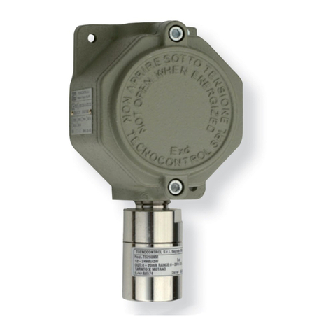
Tecnocontrol SE221KM User manual

Tecnocontrol

Tecnocontrol SE221KM User manual

Tecnocontrol TS293IM User manual

Tecnocontrol

Tecnocontrol TS293IM User manual

Tecnocontrol TS282IF User manual

Tecnocontrol

Tecnocontrol TS282IF User manual

Tecnocontrol TS282E Series User manual

Tecnocontrol

Tecnocontrol TS282E Series User manual

Tecnocontrol SE296KM User manual

Tecnocontrol

Tecnocontrol SE296KM User manual

Tecnocontrol SE126K User manual

Tecnocontrol

Tecnocontrol SE126K User manual

Tecnocontrol SE137PM User manual

Tecnocontrol

Tecnocontrol SE137PM User manual

Tecnocontrol SE193K Series User manual

Tecnocontrol

Tecnocontrol SE193K Series User manual

Tecnocontrol SE138K User manual

Tecnocontrol

Tecnocontrol SE138K User manual

Tecnocontrol TS292KM User manual

Tecnocontrol

Tecnocontrol TS292KM User manual

Tecnocontrol TS293PE User manual

Tecnocontrol

Tecnocontrol TS293PE User manual

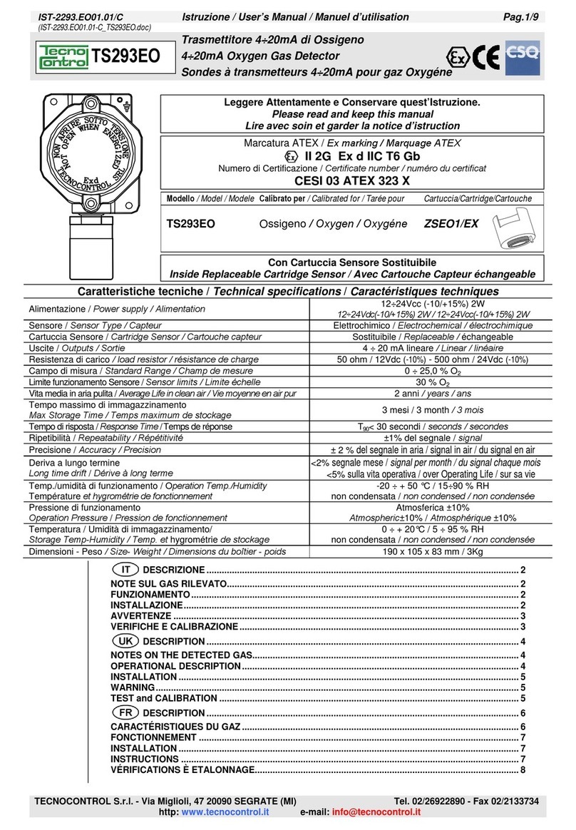
Tecnocontrol TS293EO User manual

Tecnocontrol

Tecnocontrol TS293EO User manual

Tecnocontrol TS220EC-S User manual

Tecnocontrol

Tecnocontrol TS220EC-S User manual

Tecnocontrol TS293P Series User manual

Tecnocontrol

Tecnocontrol TS293P Series User manual

Tecnocontrol SE237E Series User manual

Tecnocontrol

Tecnocontrol SE237E Series User manual

Tecnocontrol SE136IC2 User manual

Tecnocontrol

Tecnocontrol SE136IC2 User manual

Tecnocontrol Beta Series User manual

Tecnocontrol

Tecnocontrol Beta Series User manual

Tecnocontrol TS293PM User manual

Tecnocontrol

Tecnocontrol TS293PM User manual

Tecnocontrol GAMMA 653 User manual

Tecnocontrol

Tecnocontrol GAMMA 653 User manual

Tecnocontrol SE182PM User manual

Tecnocontrol

Tecnocontrol SE182PM User manual

Tecnocontrol TS282K Series User manual

Tecnocontrol

Tecnocontrol TS282K Series User manual

Tecnocontrol TS282PM User manual

Tecnocontrol

Tecnocontrol TS282PM User manual

Tecnocontrol TS293E  Series User manual

Tecnocontrol

Tecnocontrol TS293E Series User manual

Tecnocontrol TS293KM User manual

Tecnocontrol

Tecnocontrol TS293KM User manual

Popular Gas Detector manuals by other brands

PCE Instruments PCE-FGD Series user manual

PCE Instruments

PCE Instruments PCE-FGD Series user manual

Alecto COA-28 manual

Alecto

Alecto COA-28 manual

Honeywell SEARCHZONE SONIK quick start guide

Honeywell

Honeywell SEARCHZONE SONIK quick start guide

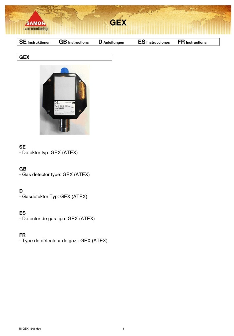
Samon GEX-(NH3)-4000 instructions

Samon

Samon GEX-(NH3)-4000 instructions

Det-Tronics PointWatch Eclipse PIRECL instructions

Det-Tronics

Det-Tronics PointWatch Eclipse PIRECL instructions

Southern Cross 46 HAWK 3.0 manual

Southern Cross

Southern Cross 46 HAWK 3.0 manual

Pfeiffer Vacuum ASM 306S operating instructions

Pfeiffer Vacuum

Pfeiffer Vacuum ASM 306S operating instructions

Sentry ST313A instruction manual

Sentry

Sentry ST313A instruction manual

Critical Environment Technologies CGAS-A installation manual

Critical Environment Technologies

Critical Environment Technologies CGAS-A installation manual

Detcon SmartWireless CXT Operator's installation and instruction manual

Detcon

Detcon SmartWireless CXT Operator's installation and instruction manual

SENKO SI-300 operating manual

SENKO

SENKO SI-300 operating manual

Sensitron GAS TEST KIT instruction manual

Sensitron

Sensitron GAS TEST KIT instruction manual

ION TIGER LT user manual

ION

ION TIGER LT user manual

DALEMANS D-TEX3F+ instruction manual

DALEMANS

DALEMANS D-TEX3F+ instruction manual

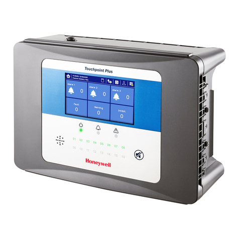
Honeywell Touchpoint Plus user guide

Honeywell

Honeywell Touchpoint Plus user guide

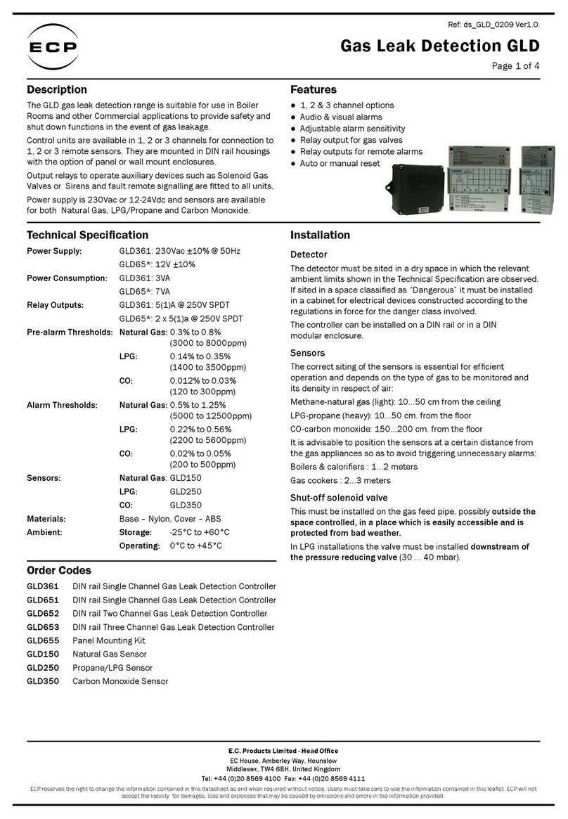
ECP GLD361 quick start guide

ECP

ECP GLD361 quick start guide

FORENSICS DETECTORS FD-VAPE-WALL user manual

FORENSICS DETECTORS

FORENSICS DETECTORS FD-VAPE-WALL user manual

Bacharach IAM-100 Installation and operation manual

Bacharach

Bacharach IAM-100 Installation and operation manual

manuals.online logo
manuals.online logoBrands
  • About & Mission
  • Contact us
  • Privacy Policy
  • Terms and Conditions

Copyright 2025 Manuals.Online. All Rights Reserved.