IST-2282.IF01.01 Istruzione / User’s Manual / Manuel d’utilisation Pag.4/9
TECNOCONTROL S.r.l. Via Miglioli 47 SEGRATE ( MI ) ITALY
“TEST ELETTRICO” (Codice Test: F2, F2, F1, F1) permette di effettuare un test funzionale del rilevatore. Dopo
aver inserito il “Codice Test”, si spengono tutti i LED e si accenderanno in sequenza dal giallo al rosso. L’uscita
4÷20mA rimane invariata. Alla fine, tutti i LED rimarranno accesi per circa 5 secondi, poi il rilevatore tornerà nelle
condizioni di funzionamento normale. Si consiglia di eseguire quest’operazione ogni 12 mesi in base all’utilizzo.
Nota: l’operazione non è eseguibile se è acceso il LED Rosso o se l’uscita in mA è olt e i 12mA (500ppm).
“VERIFICA” (Non serve Codice): serve per controllare la corretta risposta del rilevatore al gas e può essere esegui-
ta dopo l’installazione, ma va eseguita soprattutto durante le manutenzioni periodiche.
Nota im ortante: La miscela da utilizzare è la specifica miscela di Gas Refrigerante in base al modello (500 o
1000 m) in azoto. (fo nibile a ichiesta). Solo se il risultato del test risulta negativo, procedere con la Regola-
zione dello ZERO.
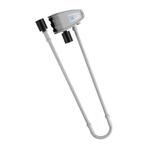
Infilare il TC014 sul sensore, regolare il riduttore della bombola in modo che il flussometro indichi da 0,3 a 0,5 l/min
(vedi Fig.3). Cont olla e, che con i puntali del voltmet o sui Test-Point “TESTmV” (vedi Fig.2), si aggiunga il valo e in
mV indicato in Tabella 3-Colonna 5 [ovvero che l’uscita in mA aumenti fino al valore indicato nella Colonna 6 (±0,2mA e la centrale,
cui è collegato il rilevatore, indichi il valore in indicato in Colonna 7]. Se il valore fosse diverso, eseguire la “Regolazione dello Ze-
ro”. Terminata la “Verifica”, chiudere la bombola e togliere il TC014. L’uscita tornerà progressivamente a 4 mA.
Es mpio se si deve ve ifica e un TS282IF2-H (con FS 1000ppm di R404a), utilizzando la bombola di R404a a
1000ppm in Azoto, l’uscita in mA dov à esse e ci ca 20,0 mA (cioè ci ca 200mV su “TESTmV”).
“REGOLAZIONE DELLO ZERO” (Codice di Zero F2, F1, F1, F2): permette di regolare manualmente il sensore a
Zero e va eseguita solo in aria pulita (ambiente senza la p esenza di gas o vapo i di aloca bu i) oppure utilizzando
una bombola di Azoto e solo quando il rilevatore è acceso da alm no 4 or . Se necessario, eseguire questa ope-
razione dopo aver verificato che il sensore non rileva correttamente gas od ogni 6-12 mesi in base alle condizioni
ambientali. Dopo aver inserito il “Codice di Zero”, come conferma dell’avvenuta operazione, ci sarà 1 lampeggio
del LED osso e l’uscita diventerà 4,0 mA.
AVVERTENZA: Non è possibile eseguire l’operazione se il rilevatore sta rilevando gas e l’uscita in mA è superiore
a 500 ppm o se è acceso il LED rosso. Se fosse acceso il LED giallo sostituire il rilevatore o inviarlo al fornitore
per la riparazione.
NOTA IMPORTANTE: La “Calib azione di SPAN” del Sensore Infrarosso, normalmente non è necessaria per i 5
anni di vita del sensore. Se dopo la VERIFICA e la REGOLAZIONE DELLO ZERO il risultato fosse negativo, invia e il ile-
vato e al fo nito e pe sostitui e il Sensore Infrarosso.
DESCRIPTION
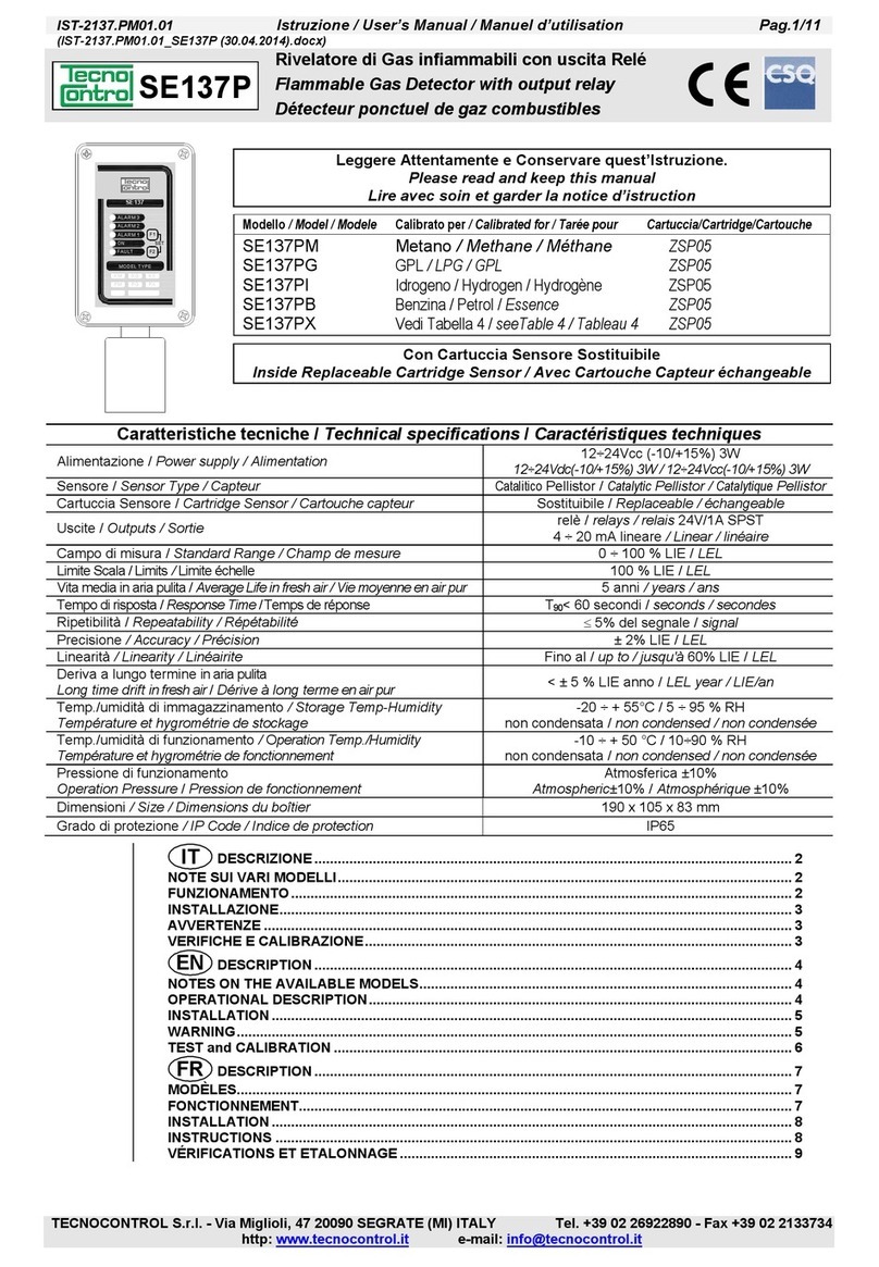
The TS282IF series is a gas detector for r frig rant gas s (halocarbons) with a NDIR – Non Dispersive Infrared Sen-
sor, calibrated for the specific gas detected, with excellent selectivity towards the other HFC gases and find their
best application in centralized alarm systems for industries of refrigerants, laboratories, cylinders warehouses stor-
age, compressors rooms, and environments in general where it is necessary to monitor any leaks of refrigerant
gases. The code of each model identifies the type of gas detected and its full scale.
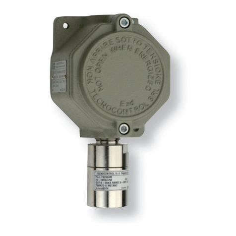
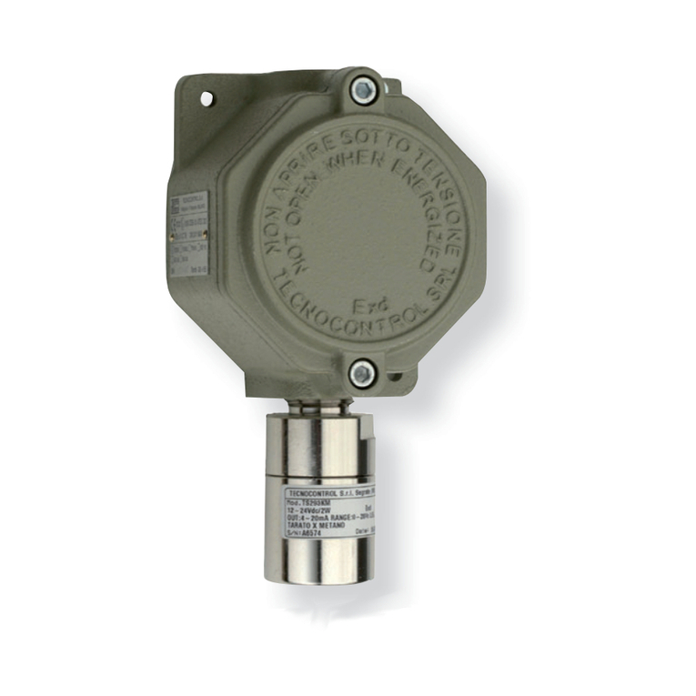
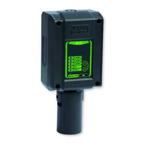
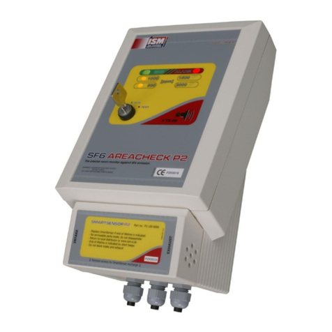
The instruments, consists of a housing that contains the electronic circuit and the connection terminal. The sensor
is inside the sensor holder (NOT OPENING), located in the lower part of the housing.
The TS282IF series has a 4÷20mA linear output (S) with 1000 (TS282IFn-H) o di 2000 (TS282IFn) ppm F.S. of
detected gas (see table on page 1). This output is connectable to a remote Gas Central Unit as listed in Table 1. On
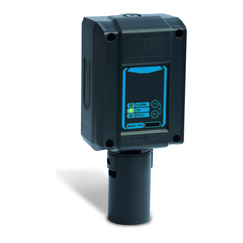
the front panel there are two F1 e F2 key, using for the Test and Calibration routine, protected by a code, and 3
LED shows the working conditions:
R d LED "ALARM": 500 ppm alarm indication (see Table 2).
Gr n LED "ON": normal working condition
Y llow LED "FAULT": the sensor should be faulty, disconnected or expired.
OPERATIONAL DESCRIPTION
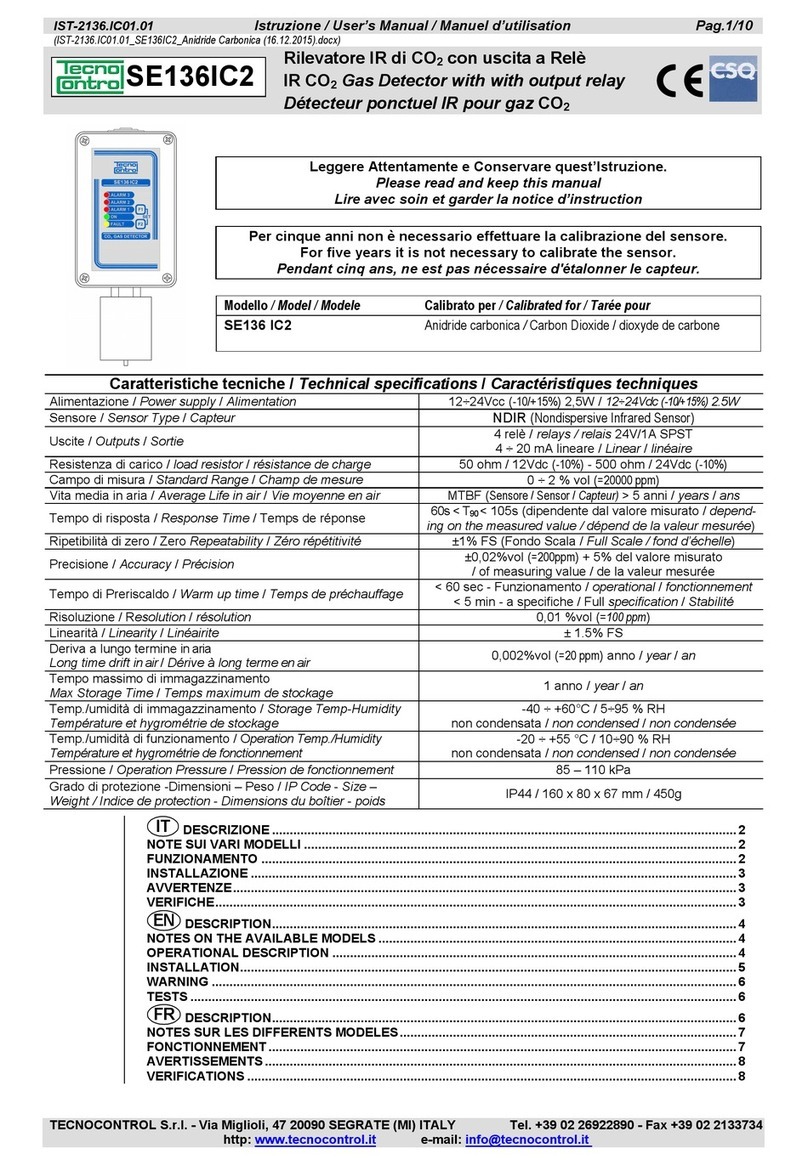
The NDIR sensor can be used in polluted environments without a significant degradation of performance and also
works in environments with oxygen deficiency.
The operational mode of the NDIR sensor is based on the physical principle that certain types of gases absorb
certain wavelengths of infrared energy. In practice, a filament generates infrared energy, which concentrated,
passes through the gas to be measured, and arrives at the detector. The detector is double, the first, defined as
“active”, has an optical filter, selective to detect the gas to be measured, while the second, called "reference" has a
filter with a different wavelength and provides the "zero" value. The difference signal between the two detectors
provides the value of the gas concentration. The advantage of this technique is that it is selective for gases, and
also has the advantage of compensating, in time, the changes of detector sensitivity. The only interference, may be
given from presence of water vapour, which absorbs infrared.
Pr h ating: when powered, the sensor needs a time of preliminary heating of about 60 s conds. During this pe-
riod the yellow LED “FAULT” flashes. After this period, the yellow LED light off, the green LED “ON” illuminates to in-
dicate normal functioning. After this period the unit is able to detect gas even if it attains the optimum stability con-
ditions after about 4 hours continual functioning (the checks can be pe fo med only afte this time).
Normal op ration: the green LED “ON” should be light on.
Alarm: when the gas concentration exceeds the value indicated in the table, the red LED illuminates (only if it be
activate by Dip-Switch).


