IST-2136.IC01.01 Istruzione / User’s Manual / Manuel d’utilisation Pag.4/10
TECNOCONTROL S.r.l. Via Miglioli 47 SEGRATE ( MI ) ITALY
È possibile usare bombole monouso, complete di valvola d’erogazione, inoltre necessario usare il kit di
prova Tecnocontrol mod. TC011 oppure TC014.
“TEST ELETTRICO” (Codice Test: F2, F2, F1, F1) permette di effettuare un test funzionale del rilevatore. Dopo
aver messo l’impianto in sicurezza ed aver inserito il “Codice Test”, si spengono tutti i Led e si disattivano tutti i re-
l . Quindi si accenderanno in sequenza, i Led, dal giallo al 3° rosso. All’accensione dei Led corrisponde
l’attivazione dei relativi rel (relè "FAULT" con il Led giallo, relè "ALARM1" con il 1° Led rosso, relè "ALARM2" con il 2° Led rosso, relè
"ALARM3" con il 3° Led rosso). Alla fine, tutti i Led rimarranno accesi per 5 secondi, poi il rilevatore tornerà nelle condi-
zioni di funzionamento normale. È consigliabile eseguire questo Test ogni 6-12 mesi in base all’utilizzo.
Nota: Non possibile eseguire l’operazione se sono già accesi il 1° e/o il 2° e/o il 3° Led Rossi.
“VERIFICA CON GAS” ( on serve Codice): serve per controllare la corretta risposta del rilevatore al gas e può es-
sere eseguita dopo l’installazione, ma va eseguita soprattutto durante le manutenzioni periodiche.
NOTA: utilizzare la miscela di gas sopra indicata. Normalmente sufficiente effettuare la Verifica della Taratura,
(Bombola 1% Volume CO2 in azoto) ma possibile anche effettuare la Verifica dello Zero (Bombola Aria Zero).
Infilare il TC011/TC014 sul portasensore, regolare il riduttore della bombola in modo che il flussometro indichi da
0,3 l/min (vedi Fig. 3) Attendere circa 3 minuti e controllare che il rilevatore vada in allarme come decritto nel capito-
lo “Funzionamento”. Se il risultato fosse molto diverso, contattare il nostro servizio assistenza. Terminata la “Verifica
con Gas”, chiudere la bombola, togliere il TC011. Considerare che progressivamente il rilevatore ritornerà alle con-
dizioni normali.
NOTA: In aggiunta a quanto sopra, se si usa anche l’uscita in mA, Infilare il TC011/TC014 sul portasensore, rego-
lare il riduttore della bombola in modo che il flussometro indichi 0,3 l/min (vedi Fig.3). ontrollare, che con i puntali
del voltmetro sui Test-Point “TEST mV” (TP1 e TP2), (vedi Fig.2) si raggiunga il valore in mV indicato in Tabella 4-Colonna
6 [ovvero che l’uscita in mA aumenti fino al valore indicato nella Colonna 7 (± 0,56 mA) e la centrale, cui è collegato il rilevatore, indichi il
valore in indicato in Colonna 8]. Se il valore fosse molto diverso, contattare il nostro servizio assistenza. Terminata la
“Verifica”, chiudere la bombola e allontanare il TC011/TC014. L’uscita tornerà poi a 4 mA.
Esempio se si deve verificare un SE136 I 2, utilizzando prima la bombola con Aria Zero Pura l’uscita in mA dovrà
essere circa 4,0 mA (cioè circa 40mV su “TEST mV”), poi utilizzando la bombola con O2 a 1%vol (=10.000ppm) in
Azoto, l’uscita in mA dovrà essere circa 12 mA (±0,56mA) (cioè 114÷126mV su “TESTmV”).
EN
DESCRIPTION
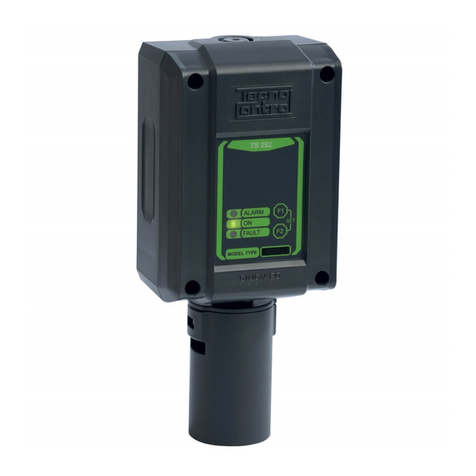
The SE136 IC2 series are gas detectors able to detect CO2 (Carbon Dioxide) by employing a N IR – Non dis-
persive Infrared Sensor, and find their best application in centralized alarm systems for laboratories, food indus-
tries (Wineries, Breweries) or environments (Greenhouses) where monitoring the amount of carbon dioxide.
The instruments is comprise of an enclosure in which the electronic circuit and the terminals are mounted; the sen-
sor is inside the sensor holder, in the lower part of the housing.
The detector has three alarm levels, with different set-up as listed in Table 2. The sealed relays are with tension free
single pole contacts (SPST) and are also settable, NO or NC by the Dip-Switch.
The instrument has also a 4÷20mA linear output (S) connectable to a remote Gas Central Unit.
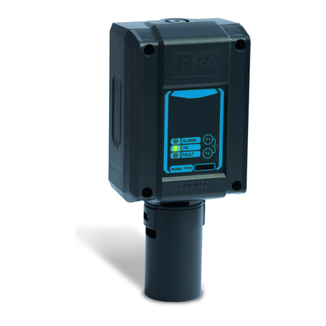
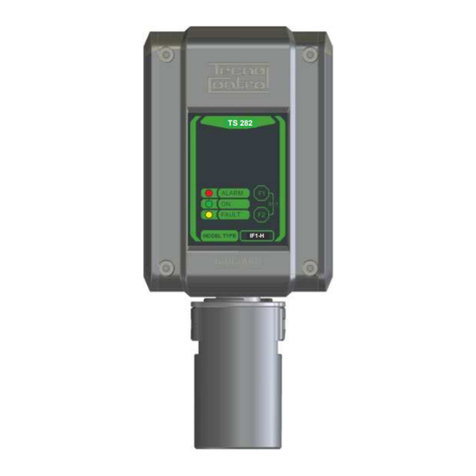
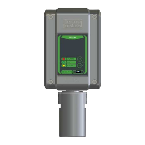
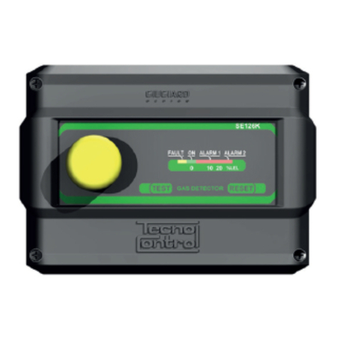
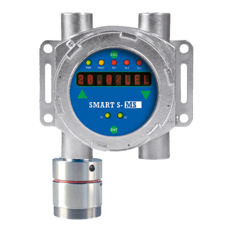
On the front panel, F1 and F2 key using for Test routine protected by a code and the 5 LED shows the functioning
conditions.
3rd Red LED "ALARM 3": 3rd relay activation
2nd Red LED "ALARM 2": 2nd relay activation
1st Red LED "ALARM 1": 1st relay activation
Green LED "ON": normal working condition
Yellow LED "FAULT": the sensor should be faulty, disconnected or expired.
NOTES ON THE AVAILABLE MODELS
The SE136 IC2 model is calibrated with a full scale of 2% volume (20000ppm) of CO2
The Carbon dioxide (synonym: Carbonic anhydride), is an odourless, colourless gas, heavier than air, its density rela-
tive to air is 1.5 and this gas can accumulate at the bottom causing a dangerous lack of oxygen. Its TWA is
5000ppm = 0.5% volume (Time-Weighted Average) and STEL 15000ppm = 1.5% volume (Short Term Exposure Limit).
Carbon dioxide is a fundamental component of Earth's atmosphere in clean air is about 400ppm and is necessary
to the life processes of plants (photosynthesis) and animals, but, for the earth's atmosphere, it is also a greenhouse
gas. The carbon dioxide is produced by combustion processes of petroleum and coal (thermal power plants and
vehicles), as a by-product of fermentation (wine, beer and organic substances), or emitted by natural processes
and by exhalations from the ground. Is used in agriculture or horticultural to increase the growth of plants, through
increase of its concentration in greenhouses, etc.
OPERATIONAL DESCRIPTION
The NDIR sensor is temperature compensated, it can be used in polluted environments without a significant deg-
radation of performance and also works in environments with oxygen deficiency.
The operational mode of the NDIR sensor is based on the physical principle that certain types of gases absorb
certain wavelengths of infrared energy. In practice, a filament generates infrared energy, which concentrated,
passes through the gas to be measured, and arrives at the detector. The detector is double, the first, defined as
“active”, has an optical filter, selective to the gas to be measured, while the second, called "reference" has a filter
with a different wavelength. The active detector is used to detect the gas, while the reference detector provides the


