Tecnogas 11589 User manual

Multimetro digitale a pinza
AC Clamp meter
Manuale OperativO |OperatiOn Manual
SKU 11589

2TECNOGAS manuale operativo |operation manual
TECNOGAS:
LA NOSTRA ESPERIENZA
AL VOSTRO SERVIZIO
TECNOGAS:
OUR EXPERIENCE
AT YOUR SERVICE
Grazie per aver acquistato questo prodotto Tecnogas. Per
la vostra sicurezza, vi consigliamo di leggere attentamente
queste istruzioni prima dell’installazione.
Al ne di non invalidare la garanzia,
consigliamo di afdarsi a installatori
e manutentori esperti.
Thank you for buying this Tecnogas product. For your
safety, please read these instructions carefully before use.
In order not to avoid guarantee,
we strongly recommend to rely
on expert technicians and service.

TECNOGAS manuale operativo |operation manual 3
•Prima dell’uso, è necessario controllare il corretto funzionamento dello strumento e lo stato dei cavetti di
misura. Non usare i cavetti di misura se questi risultano danneggiati o spellati.
Before use, it is necessary to check the proper functioning of the instrument and the leads condition.
Do not use damaged or stripped leads.
•Non superare mai il valore specicato per ciascuna portata di misura.
Do not exceed the maximum allowable input range of any function.
•Non sottoporre lo strumento ad una differenza di potenziale quando è selezionata la funzione di misura
della resistenza.
Do not apply voltage when a resistance function is selected.
•Posizionare il selettore in modalità “OFF” quando lo strumento non è in uso.
Select the “Switch OFF” function when the instrument is not in use.
•Scollegare sempre i cavetti di misura dal circuito di prova prima di agire sul selettore delle misure o sulla
portata.
Disconnect the test leads from the circuit before acting on selector switch or voltage.
•Non misurare la corrente in un circuito attraverso i cavi di misura se il voltaggio supera i 240V.
Do not measure current with test cable on a circuit if the voltage exceeds 240V.
•Durante la misurazione, non passare mai dalla modalità corrente a quella di resistenza.
During the measurement, do not switch from current to resistance mode.
•Durante le misurazioni, il proprio corpo non deve essere a contatto con inssi, macchinari o qualsiasi altro
oggetto metallico che si trovi a potenziale di terra.
During the measurements, your body must not be in contact with windows, instruments or any other
metallic object that is at ground potential.
•Usare sempre calzature isolanti per garantire l’isolamento del proprio corpo da terra.
Always use the insulating footwear to guarantee the insulation of your body from the ground.
Avvertenze per l’uso |User directions
Pericolo |Danger
Si raccomanda di seguire scrupolosamente le istruzioni contenute in questo manuale d’uso al ne di
salvaguardare la propria sicurezza e di utilizzare lo strumento in modo appropriato. La completa conformità
ai gradi di sicurezza può essere garantita soltanto quando l’utente utilizza esclusivamente i cavi in dotazione.
It is recommended to carefully read the instructions of this user manual in order to safeguard your own security
and to correctly use the AC Clamp meter. The complete compliance to the security can be guaranteed only
when the user employes the cables supplied.
Speciche generali | General specications
Temperatura di stoccaggio | Storage Temperature -30°C - 60°C | -14°F - 140°F
Umidità relativa | Relative humidity
90% (0°C - 30°C) | (35°F - 86°F)
75% (30°C - 40°C) | (86°F - 104°F)
45% (40°C - 50°C) | (104°F - 122°F)
Altitudine | Altitude 3000 m
Sovratensione | Over voltage Categoria III | Category III - 600V
Batterie | Batteries 3 Batterie AA 1.5V | 3 Batteries AA 1,5V
Dimensioni - Peso | Dimensions - Weight 220x50x30 mm | 200 g

4TECNOGAS manuale operativo |operation manual
Descrizione elementi | Elements description
Descrizione | Description
1Ganasce per misurazione corrente | Clamp for current measurement
2Leva di apertura delle ganasce | Clamp trigger
3Pulsante accensione torcia | Power torch button
4Selettore di funzioni | Function switch
5Pulsante di selezione modalità | Mode selection button
6Display LCD | LCD Display
7Pulsante per bloccare il valore sul display | HOLD button
8Pulsante per visualizzare valore MAX/MIN | MAX/MIN value button
9Pulsante misura relativa REL | REL relative measurement button
10 Connettore per cavo di misura rosso | Red test rod input jack
11 Connettore per cavo di misura nero | Black test rod input jack
10
4
3
7
11
6
8
9
1
2
5

TECNOGAS manuale operativo |operation manual 5
Composizione del prodotto | Product components
Componenti del Kit | Kit components
AAstuccio contenitore | Professional case
BMultimetro digitale a pinza | AC Clamp meter
CCavo di misura nero | Black test leads
DCavo di misura rosso | Red test leads
ETermocoppia per misurazione temperatura | Diodes (thermocouple)
Istruzioni |Instructions
B
A
C
DE
Misura della differenza di potenziale
|
Potential difference
Measurements
1. Posizionare il selettore di funzioni (4 ) su V.
Set the function switch (4 ) on V.
2. Inserire il cavo nero (C ) sul terminale negativo (11 ) e il cavo rosso ( D ) sul terminale positivo ( 10 ).
Insert the black test (C ) lead into the negative terminal (11 ) and the red test cable ( D ) into the
positive terminal (10 ).
3. Selezionare AC o DC con il pulsante “SELECT” (5 ).
Select AC or DC with “SELECT” button (5 ).
4. Collegare i cavi di misura (C e D )in parallelo al circuito. Sul display (6 ) apparirà la lettura.
Connect the black and red test leads (C and D )in parallel to the circuit. The potential difference
value will appear on LCD display (6 ).
5. Se necessario, passare all’impostazione relativa della misurazione tramite il tasto “REL” (9 ).
If necessary, push the “REL” button (9 ) to switch relative measurement of the potential difference.
6. Per visualizzare i valori MAX e MIN premere il tasto 8 . Per tornare alla misurazione assoluta,
premere il tasto 8 per 2 secondi.
Pust the button 8 to see the MAX and MIN values. To come back to the absolute measurement,
press the button 8 for two seconds.

6TECNOGAS manuale operativo |operation manual
Misura della resistenza
|
Resistance Measurements
1. Inserire il cavo nero (C ) sul terminale negativo (11 ) e il cavo rosso ( D ) sul terminale positivo ( 10 ).
Insert the black test (C ) lead into the negative terminal (11 ) and the red test cable ( D ) into the
positive terminal (10 ).
2. Posizionare il selettore di funzioni (4 ) su Ω.
Set the function switch (4 ) on Ω.
3. Toccare con i cavi di misura l’elemento da misurare. Sul display (6 ) apparirà la lettura della
resistenza.
Touch with the test leads across the circuit or component under test. The resistance value will appear
on LCD display (6 ).
4. Per visualizzare i valori MAX e MIN premere il tasto 8 . Per tornare alla misurazione assoluta,
premere il tasto 8 per 2 secondi.
Pust the button 8 to see the MAX and MIN values. To come back to the absolute measurement,
press the button 8 for two seconds.
Modalità di test per diodi
|
Test mode for diodes
1. Inserire il cavo nero (C ) sul terminale negativo (11 ) e il cavo rosso ( D ) sul terminale positivo ( 10 ).
Insert the black test (C ) lead into the negative terminal (11 ) and the red test cable ( D ) into the
positive terminal (10 ).
2. Posizionare il selettore di funzioni (4 ) su Ω.
Set the function switch (4 ) on Ω.
3. Premere una volta il tasto “SELECT” (5 ) per far apparire sul display (6 ) il simbolo “->
|
”
Push ince the “MODE” button (5 ) to select the “->
|
” symbol on display (6 ).
Misura della frequenza o % ciclo di lavoro
|
Frequence or duty cycle measurements
1. Inserire il cavo nero (C ) sul terminale negativo (11 ) e il cavo rosso ( D ) sul terminale positivo ( 10 ).
Insert the black test (C ) lead into the negative terminal (11 ) and the red test cable ( D ) into the
positive terminal (10 ).
2. Posizionare il selettore di funzioni (4 ) su Hz/%.
Set the function switch (4 ) on Hz/%.
3. Selezionare Hz o % con il pulsante SELECT (5 ).
Select Hz or % with the SELECT button (5 ).
4. Far toccare ai cavi del multimetro le parti del circuito che si vogliono misurare. Sul display (6 )
apparirà la lettura della frequenza o della percentuale di lavoro.
Touch with the test leads the parts of the circuit or component under test. The frequency or duty cycle
(%) value will appear on LCD display (6 ).
5. Se necessario, passare all’impostazione relativa della misurazione tramite il tasto “REL” (9 ).
If necessary, push the “REL” button (9 ) to switch relative measurement of the potential difference.
6. Per visualizzare i valori MAX e MIN premere il tasto 8 . Per tornare alla misurazione assoluta,
premere il tasto 8 per 2 secondi.
Pust the button 8 to see the MAX and MIN values. To come back to the absolute measurement,
press the button 8 for two seconds.
iiE’ consigliabile disconnettere uno dei due poli del dispositivo in questione dal circuito in
modo da non creare interferenze sulla resistenza letta.
It is advisable to disconnect one of two poles from the circuit to not interfere with the read
resistance.

TECNOGAS manuale operativo |operation manual 7
ii
La modalità di test per diodi fornisce informazioni utili sulla corretta polarizzazione di un
diodo e sul suo stato generale.
- Se un diodo è correttamente polarizzato, la caduta di tensione dovrebbe aggirarsi tra
0,5 e 0,8 V (per i diodi in Silicio) o tra 0,2 e 0,3 (per quelli in Germanio) se misurata in
senso diretto. Nell’altro senso, la misura dovrebbe essere “0L”.
- Se il diodo è in cattivo stato, la misura rilevata è in entrambi i sensi “0L” (interruttore
aperto in entrambe le direzioni).
- Se il diodo è cortocircuitato, la misura della caduta di tensione è nulla o uguale in
entrambi i sensi di misura.
The test mode for diodes gives useful information about the proper polarization of a diode
and its general state.
- If a diode is properly polarized, the voltage drop measured in direct way should be
between 0,5 and 0,8 V (for silicon diode) and between 0,2 and 0,3 V (for germanium
diode). On the other way, the measured voltage drop should be “OL”.
- If a diode is damaged, the voltage drop should be “OL” in both measured ways (the
switch is open in both directions).
- If a diode is shorted, the measured voltage drop is zero or equal in both directions.
Misura della continuità
|
Continuity
measurements
1. Inserire il cavo nero (C ) sul terminale negativo (11 ) e il cavo rosso ( D ) sul terminale positivo ( 10 ).
Insert the black test (C ) lead into the negative terminal (11 ) and the red test cable ( D ) into the
positive terminal (10 ).
2. Posizionare il selettore di funzioni (4 ) su Ω.
Set the function switch (4 ) on Ω.
3. Premere il tasto “SELECT” (5 ) per far apparire sul display (6 ) il simbolo
Press the “SELECT” button (5 ) to select the symbol on LCD display (6 ).
4. Toccare con i cavi di misura l’elemento di cui verificare la continuità. Sul display (6 ) apparirà la
lettura della resistenza rilevata e, se il valore è inferiore a 1000 Ω, si udirà un segnale acustico.
Touch with the test leads the elements on which check the continuity. The measured resistance will
appear on LCD display (6 ). If the value is <1000 Ω, an acoustic signal will be heard.
ii
Prima di effettuare qualsiasi misura della capacitanza, è necessario togliere la corrente
dal dispositivo e scaricare tutti i condensatori per evitare qualsiasi shock elettrico. Inoltre,
rimuovere le batterie o scollegare i cavi elettrici dal generatore di tensione.
Before any capacitance measurement, it is necessary to disconnect the power from the
device to be measured and to discharge all capacitors. In addition, remove the batteries
and unplug the electric cables.
Misura della capacitanza
|
Capacitance Measurements
1. Inserire il cavo nero (C ) sul terminale negativo (11 ) e il cavo rosso ( D ) sul terminale positivo ( 10 ).
Insert the black test (C ) lead into the negative terminal (11 ) and the red test cable ( D ) into the
positive terminal (10 ).
2. Posizionare il selettore di funzioni (4 ) su .
Set the function switch (4 ) on .
)
)
)
)
)
)
4. Toccare con i cavi (C e D ) di misura il diodo di cui verificare la polarizzazione e la continuità. Sul
display (6 ) apparirà la lettura della caduta di tensione rilevata.
Touch with the test leads (C and D ) the diode which to test the polarization and the continuity. The
voltage drop value will appear on LCD display (6 ).

8TECNOGAS manuale operativo |operation manual
iiPrima di entrare in modalità di misurazione Temperatura e prima di uscirne è necessario
disconnettere i cavi di misura.
Before measure the temperature, it is necessary to disconnect both test leads from any
source of voltage.
ATTENZIONE: Questa funzione misura solo la presenza di tensione in un conduttore, ma non da
indicazioni di potenziale, intensità di corrente, corrente di messa a terra, ecc...
WARNING: This function measures only the presence of voltage in a conductor and does not
provide information about the potential, current intensity, earth ground current, etc...
Misura della temperatura
|
Temperature Measurements
1. Inserire il cavo nero (C ) sul terminale negativo (11 ) e il cavo rosso ( D ) sul terminale positivo ( 10 ).
Insert the black test (C ) lead into the negative terminal (11 ) and the red test cable ( D ) into the
positive terminal (10 ).
2. Posizionare il selettore di funzioni (4 ) su °C/°F.
Set the function switch (4 ) on °C/°F.
3. Selezionare °C o °F con il pulsante SELECT (5 ).
Select °C or °F with the SELECT button (5 ).
4. Posizionare il sensore di temperatura (E ) sull’oggetto che si vuole misurare. Per avere una
misurazione il più possibile precisa, lasciare almeno 30 secondi il sensore sulla superficie. Sul
display (6 ) apparirà la lettura della temperatura.
Set the temperature sensor (thermocouple) (E ) on the object you wish to measure. Leave the
sensor on the object surface at least 30 seconds to have an exact estimate. The temperature value
will appear on LCD display (6 ).
5. Se necessario, passare all’impostazione relativa della misurazione tramite il tasto “REL” (9 ).
If necessary, push the “REL” button (9 ) to switch relative measurement of the potential difference.
Rilevamento della tensione senza contatto
|
Non-contact AC voltage measurement
1. Posizionare il selettore di funzioni (4 ) su NCV.
Set the function switch (4 ) on NCV.
2. Posizionare la testa della pinza ( 2 ) in prossimità del cavo che si vuole misurare, in modo da rilevare
la presenza di tensione o campo magnetico. Se la tensione del campo elettrico è maggiore di 100V e
la distanza è inferiore a 10 mm, lo strumento inizierà a suonare e la luce rossa del led a lampeggiare.
Arrange the clamp head (2 ) near the tested wire, in order to detect the existence of AC voltage ore
electromagnetic field. When the electric field voltage is higher than 100V AC and the distance is shorter
than 10 mm, the buzzer will ring and LED red light will flash.
3. Toccare il condensatore da misurare con i cavi di misura (C e D ). Leggere il valore della
capacitanza sul display LCD (6 ).
Touch the capacitor to be measured with the test leads (C and D ). Read the capacitance value
on LCD display (6 ).

TECNOGAS manuale operativo |operation manual 9
Misura della corrente in sistemi AC tramite la pinza amperometrica
|
AC Current Measurements with clamp meter
iiMisurare un solo conduttore per volta.
Measure the conductor one at a time to obtain reliable measurements.
•Il pulsante HOLD (7 ) serve per bloccare il valore presente sul display LCD ( 6 ).
The HOLD button (7 ) is useful to freeze the value the LCD display ( 6 ).
•Per accendere il LED luminoso premere il pulsante 3 per 2 secondi. Per spegnerlo premere una
sola volta.
Press the button 3 for 2 seconds to switch on the LED. Press once to switch off the LED.
•Premere il pulsante 7 per 2 secondi per accendere la luce del display 6 . La luce si spegnerà
automaticamente dopo circa 15 secondi.
Press the button 7 for 2 seconds to switch on the display light 6 . The light will switch off
automatically after about 15 seconds.
Altre informazioni |More information
•Per cambiare le batterie allo strumento, aprire il vano posto sul retro dello strumento tramite un
cacciavite a croce.
To replace the batteries of the instrument, it is necessary to open the cover placed on the back usign
a phillip’s screwdriver.
•Sostituire le 3 batterie AA con altre dello stesso stato di carica e della stessa tipologia.
Replace the 3 AA batteries with others of the same type and and of the same charge status.
•Non utilizzare batterie di diverso tipo o una batteria carica ed una scarica.
Do not use batteries of different type or one charged battery coupled with a low battery.
Sostituzione batteria |Battery replacement
1. Posizionare il selettore di funzioni (4 ) su A.
Set the function switch (4 ) on A.
2. Premere la leva di rilascio (2 ) delle ganasce e chiudere internamente il conduttore da misurare. Sul
display (6 ) apparirà la lettura della corrente.
Push the trigger (2 ) to open the clamps and then fully enclose the conductor to be measured. The
current value will appear on LCD display (6 ).
3. Se necessario, passare all’impostazione relativa della misurazione tramite il tasto “REL” (9 ).
If necessary, push the “REL” button (9 ) to switch relative measurement of the potential difference.
4. Per visualizzare i valori MAX e MIN premere il tasto 8 . Per tornare alla misurazione assoluta,
premere il tasto 8 per 2 secondi.
Pust the button 8 to see the MAX and MIN values. To come back to the absolute measurement,
press the button 8 for two seconds.
10 TECNOGAS manuale operativo |operation manual
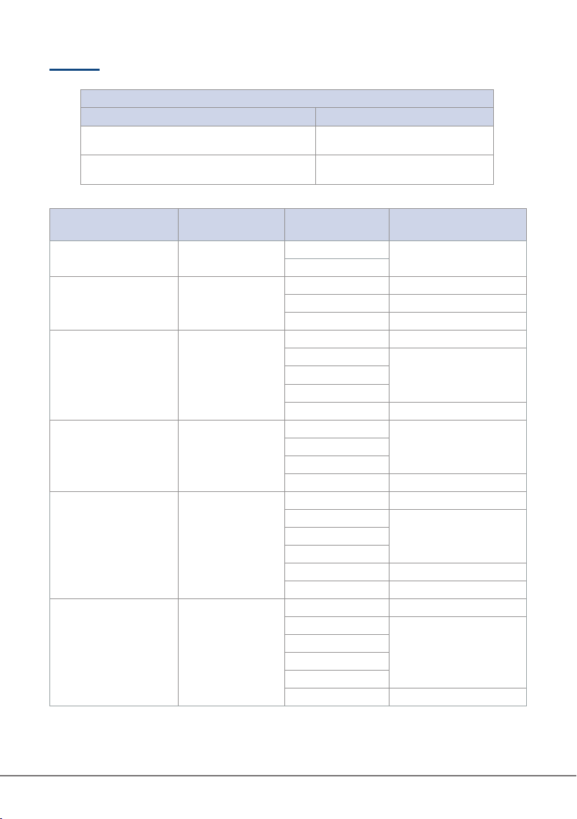
Specifiche tecniche |Technical specifications
Limite valori | Input limits
Funzione | Functions Valore massimo | Maximum input
A - AC (con pinza amperometrica)
A - AC (with clamp meter) 400 A
V DC, V AC, Frequenza, Ciclo di lavoro
V DC, V AC, Frequency, Duty cycle 600V DC/AC
Funzione | Function Risoluzione
Resolution Range | Range Accuratezza | Accuracy
(%)
Corrente continua DC
DC Current 0,1 µA 400 µA ±(2% + 3 digits)
4000 µA
Corrente alternata AC
AC Current 0,1 A
4 AAC ±(2,5% + 30 digits)
40 AAC ±(1,8% + 9 digits)
400 AAC ±(2,5% + 5 digits)
Tensione DC
DC Voltage 0,1 mV
400 mVDC ±(1% + 8 digits)
4 VDC
±(0,8% + 3 digits)40 VDC
400 VDC
600 VDC ±(1% + 3 digits)
Tensione AC
AC Voltage 0,1 V
4 V
±(1,2% + 5 digits)40 V
400 V
600 V ±(1,5% + 5 digits)
Resistenza
Resistance 0,1 Ω
400 Ω±(1,2% + 2 digits)
4K Ω
±(1% + 2 digits)40K Ω
400K Ω
4M Ω±(1,2% + 3 digits)
40M Ω±(2% + 5 digits)
Capacitanza
Capacitance 0,1 nF
40 nF ±(4% + 25 digits)
400 nF
±(4% + 5 digits)
4 µF
40 µF
400 µF
4 mF ±(10%)

TECNOGAS manuale operativo |operation manual 11
Temperatura
Temperature 0,1°C / 1°F
-40°C~+40°C /
-40°F~104°F ±(3% + 5 digits)
+40°C~+400°C /
+104°F~752°F
+400°C~+100°C /
+752°F~1832°F ±(1% + 3 digits)
Frequenza
Frequency
Sensitivity:
200mVrms ≤ input
amplitude ≤ 20Vrms
0,01 Hz
~
1kHz
10 Hz
~
1MHz
±(0,1% + 4 digits)

Table of contents
Other Tecnogas Measuring Instrument manuals


