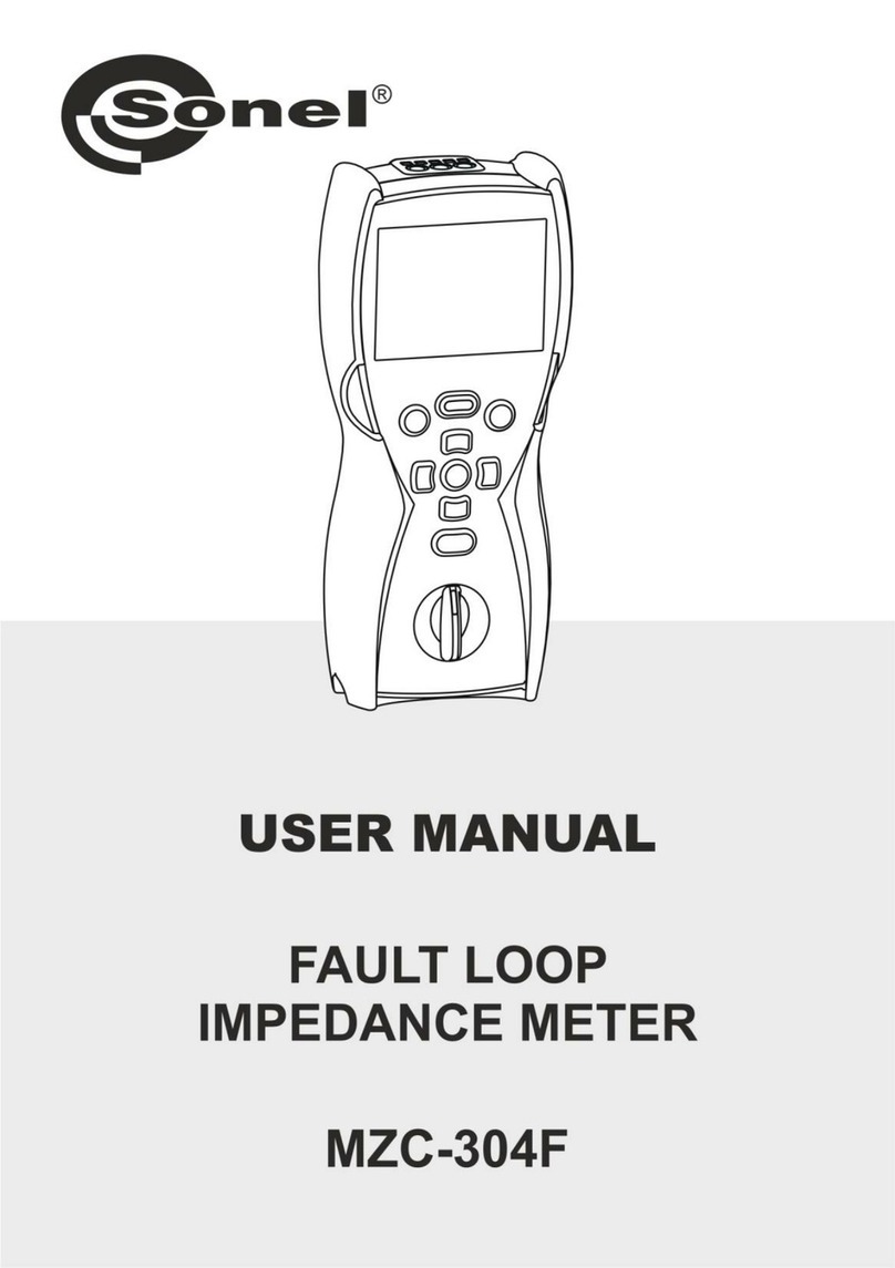
Sonel MZC-310S User manual


OPERATING MANUAL
SHORT-CIRCUIT LOOP
IMPEDANCE METER
MZC-310S
SONEL SA
ul. Wokulskiego 11
58-100 Świdnica
Version 3.6


3
TABLE OF CONTENTS
1PREFACE ......................................................................................................5
2INTRODUCTION............................................................................................6
3SAFETY .........................................................................................................6
4DEVICE DESCRIPTION AND ITS FUNCTIONALITY...................................6
4.1 MZC-310S CHARACTERISTICS....................................................................6
4.2 STANDARD ACCESSORIES...........................................................................7
4.3 OPTIONAL ACCESSORIES ............................................................................7
4.4 TERMINALS AND KEYS LAYOUT....................................................................8
4.4.1 Terminals .......................................................................................................8
4.4.2 Keyboard........................................................................................................9
4.5 GRAPHICAL DISPLAY PANEL (LCD)............................................................10
4.6 BUZZER....................................................................................................11
4.7 TEST LEADS .............................................................................................12
5STORAGE....................................................................................................13
6BEFORE YOU START.................................................................................13
7OPERATIONS..............................................................................................14
7.1 PREPARING THE DEVICE FOR WORK..........................................................14
7.2 POWER SUPPLY VOLTAGE MONITORING ....................................................15
7.3 BATTERY REPLACEMENT...........................................................................15
7.4 CONDITIONS FOR PERFORMING TESTS AND OBTAINING CORRECT RESULTS 16
7.5 DEVICE CONNECTION DIAGRAMS...............................................................17
7.6 MEASUREMENT OF ALTERNATING VOLTAGE ...............................................22
7.7 SHORT-CIRCUIT LOOP MEASUREMENT ......................................................22
7.7.1 Measurement of Network Voltage and Frequency .......................................23
7.7.2 Changing The Network Rated Voltage.........................................................23
7.7.3 Displaying All Measurement Results Or The Main Result Only....................24
7.7.4 Displaying The Measurement Results In Terms of Impedance or Short-
Circuit Current..............................................................................................24
7.7.5 Measurement of Touch Voltage UST And Touch Shock Voltage UT.............25
7.7.6 Selection of Test Cables Length (For Measurements Using Two-Pole
Method)........................................................................................................25
7.7.7 Results Display ............................................................................................26
7.7.8 Measurement of Short-Circuit Loop Parameters Using Two-Pole Method...26
7.7.9 Measurement of Short-Circuit Parameters By the Four-Pole Method ..........26
7.8 MEASUREMENT OF EARTHING RESISTANCES..............................................27
7.9 SAVING THE MEASUREMENT RESULTS.......................................................28
7.9.1 Storing Measurement Results In The Memory.............................................29
7.9.2 Memory Browsing ........................................................................................30
7.9.3 Erasing the memory.....................................................................................30

4
7.10 MENU.......................................................................................................31
7.10.1 Display Contrast Adjustment........................................................................31
7.10.2 Data Transmission .......................................................................................31
7.10.3 Display settings............................................................................................31
7.10.4 Loop Measurement Settings ........................................................................32
7.10.5 Language Selection .....................................................................................32
7.10.6 Advanced Functions.....................................................................................32
7.10.6.1 Expected Dispersion of Results ...................................................................32
7.10.6.2 Upgrading The Software ..............................................................................33
7.10.7 Information About The Manufacturer And The Software..............................34
7.11 SENDING DATA TO A COMPUTER................................................................34
7.11.1 Communications Kit .....................................................................................34
7.11.2 Connecting The Meter To A Computer.........................................................34
8TROUBLE SHOOTING................................................................................35
8.1 WARNINGS AND INFORMATION DISPLAYED BY THE METER.........................35
8.1.1 Exceeding The Measurement Range...........................................................35
8.1.2 Battery Status Display..................................................................................35
8.2 SELF-TEST ERROR MESSAGES..................................................................35
8.3 BEFORE YOU SEND THE DEVICE FOR REPAIRS...........................................35
9CLEANING AND MAINTENANCE..............................................................36
10 DECOMMISSIONING AND RECYCLING...................................................36
11 APPENDICES..............................................................................................37
11.1 TECHNICAL SPECIFICATIONS .....................................................................37
11.2 MANUFACTURER.......................................................................................39

5
1 Preface
Thank you for purchasing our short-circuit loop impedance meter. MZC-310S is a state-of-the-art,
high-quality measuring instrument that is easy and safe to operate. However, familiarising with this
manual will let you avoid measurement errors and will prevent possible problems that might occur
while operating the device.
In this instruction we use three types of warnings. They are shown as a framed text and describe
possible hazards for either the user of the device. Texts that start with the word “WARNING:” describe
a life threatening or hazardous situation that can result if the instructions are not followed. Wherever a
“CAUTION!” exclamation opens the framed text, it describes a situation where non-adherence to the
manual can result in damage to the meter. Possible problems that may occur are preceded with the
word “Note:”.
WARNING:
Before starting to use the device, please read carefully this manual, always follow all health
and safety rules and comply with manufacturer’s recommendations.
WARNING:
MZC-310S meter is designed to measure short-circuit loop impedance and alternating volt-
ages. Using the device for purposes other then described in this manual can cause an injury
to the operator and/or can damage the device.
WARNING:
MZC-310S may be used only by qualified personnel who is certified to work with electrical
installations. Operating the instrument by a person who is not qualified, can result in a haz-
ardous situation and/or can cause damage to the meter.
WARNING:
Using this manual does not exclude the need to comply with occupational health and safety
regulations and with other relevant fire regulations required during the performance of a par-
ticular type of work. Before starting the work with the device in special environments, e.g.
potentially fire-risk/explosive environment, it is necessary to consult it with the person re-
sponsible for health and safety.
Note:
An attempt to install drivers in 64-bit Windows 8 may result in displaying "Installation failed"
message.
Cause: Windows 8 by default blocks drivers without a digital signature.
Solution: Disable the driver signature enforcement in Windows.

6
2 Introduction
This manual describes the MZC-310S short circuit loop meter. We recommend that you familiarize
yourself thoroughly with the contents of this manual in order to avoid errors that can result in a safety
hazard or in an incorrect assessment of tested installations. More information related to safety issues
can be found in chapter 3 –Safety. Before you use the device for the first time, read carefully chapter
6 –Before You Start. If the device causes any problems, refer to chapter 8 –Trouble Shooting. All
information on how to use the device is located in chapter 7 –Operations.
3 Safety
MZC-310S device is intended for testing electric shock protection and grounding in AC power net-
works. Results obtained from readings determine the safety status of installations. Therefore, to en-
sure correct operations of the device and reliability of measurements, you need to adhere to the fol-
lowing rules:
Before starting to use the meter, you have to become thoroughly familiar with this manual.
The device should be operated only by persons holding appropriate qualifications and who at-
tended appropriate occupational health and safety training.
It is not acceptable to:
oUse the meter that is damaged in any way
oUse leads with damaged insulation
oUse a meter stored in inappropriate conditions (e.g. high humidity) for a prolonged pe-
riod of time
Before commencing a measurement, select the desired mode and make sure that the test leads
are connected to the appropriate terminals.
Repairs can be performed by an authorised service agent only.
Additional points to remember:
The text BAT! appearing in the right upper corner of the display (instead of the battery symbol) in-
dicates insufficient power supply voltage and signals a need to replace the batteries.
Measurements made with the meter with the supply voltage being too low are burdened with some
additional errors that are impossible for the user to evaluate and therefore must not be relayed up-
on when assessing if the installation tested is sufficiently protected.
4 Device Description and Its Functionality
4.1 MZC-310S Characteristics
MZC-310S is designed to measure short-circuit loop impedance and alternating voltages.
Main features of MZC-310S.
Measurement of very low short-circuit loop impedances with a current of 150A at 230V, maximum
280A at 440V (Rzw = 1,5)
Touch voltage and touch shock voltage measurement
Ability to perform a measurement with a current of 23A at 230V, maximum 42A at 440V (Rzw =
10)
Measurements in installations with rated voltages between 220/380V and 230/400V and frequen-
cies 45...65Hz
Selection of rated voltage: 220V/380V or 230V/400V
Ability to perform measurements in short-circuit system: phase-phase, phase-protective, phase-
neutral
Automatic calculation of the short-circuit current
Differentiation between the phase voltage and the inter-phase voltage while calculating the short-
circuit current

7
Automatic choice of measurement range
Ability to change the length of measurement cables without a need to re-calibrate the instrument
Measurement of alternating voltages
Memory to store 990 measurement results with an ability to transfer them to PC via an
RS-232C connection
Large, legible LCD with a backlit option
Monitoring battery’s charge status
Automatic switch-off when the instrument is not used (AUTO-OFF)
Ergonomic design
4.2 Standard Accessories
The device is supplied in a kit that contains:
MZC-310S meter –WMPLMZC310S
Set of measuring conductors:
1.2 m black conductor with pin plugs –WAPRZ1X2BLBB
1.2 m yellow conductor with pin plugs –WAPRZ1X2YEBB
Black test prod with a female connector –WASONBLOGB1
Yellow test prod with a female connector –WASONYEOGB1
3-m two-wire cable (2 pcs.) –WAPRZ003DZBB
Black crocodile clip K03 (4 pcs.) –WAKROBL30K03
Kelvin’s crocodile clip (2 pcs.) –WAKROKELK06
High current prod with a female connector –WASONSPGB1
Carrying case L1 for the meter and its accessories –WAFUTL1
Serial transmission cable RS-232 –WAPRZRS232
Meter carrying harness –WAPOZSZE1
Service manual
Calibration certificate –LSWPLMZC310
5 R14 batteries
Note:
In order to measure touch voltage use the 20 m cable included among the accessories.
4.3 Optional Accessories
Additional accessories that are not a part of the standard kit can be purchased from the manufac-
turer or from suppliers:
USB/RS232 adapter–WAADAUSBRS232
Yellow cables with pin plugs for measurements of loop impedance by means of the bipolar method
(2 pcs):
- Length: 5m –WAPRZ005YEBB
- Length: 10m –WAPRZ010YEBB
- Length: 20m –WAPRZ020YEBB
SONEL “Electric measurements” software aiding preparation of complete measurement documen-
tation –WAPROSONPE3
Software generating drafts, electric installation schematic diagrams SONEL Schematic –
WAPROSCHEM
Measurement calculation software SONEL PE Calculations –WAPROKAL

8
4.4 Terminals and Keys Layout
232
U2
MZC-310S
RS
U
2p (I =42A)
max 4p (I =280A)
max
MEM
4p
2p UB
232
U2
MZC-310S
RS
U
2p (I =42A)
max 4p (I =280A)
max
MEM
4p
2p UST/T
8
7
10
15
911 12
1
3
14
6
2
4
5
13
MAX 440V MAX 440V
Fig.1. MZC-310S front panel layout
4.4.1 Terminals
CAUTION!
MZC-310S is designed to operate at rated phase voltages of 220V and 230V and inter-
phase voltages of 380V and 400V.
Applying voltages higher than those specified to any of the test terminals can damage the
device.
1 Test terminal I1(Imax 280A)
Terminal to connect the phase current cable in the four-pole method of the short-circuit loop impedance
measurement using current not exceeding 280A.
2 Test terminal I1(Imax 42A)
Socket to connect the phase current cable in the two-pole method of the short-circuit loop impedance
measurement using current not exceeding 42A.
3 Test terminal I2
Terminal (common for both methods) to connect the neutral cable N, protective cable PE/PEN (current
cable in the four-pole method) or another phase cable in a case of a short-circuit loop impedance meas-
urement in the phase-phase configuration.
4 Test terminal U1
Terminal to connect the voltage phase cable in the four-pole method of short-circuit loop impedance
measurement or a cable to measure alternating voltage.

9
5 Test terminal U2
Terminal to connect the voltage neutral cable N or the protective cable PE (PEN) in the four-pole meth-
od of short-circuit loop impedance measurement or the cable to measure alternating voltage.
6 Test terminal UST/T (UB)
Terminal to connect the protective cable PE (PEN) in the function of touch voltage UST measurement or
an electrode (probe) in the touch shock voltage UTmeasurement mode.
7 Test terminal RS-232C
Terminal to connect a serial communications cable (RS-232C).
4.4.2 Keyboard
8 Key
Switching the device power supply on and off.
9 Rotary mode switch
Selection of measurement function:
U- measurement of alternating voltage
2p (Imax=42A) –measurement of short-circuit loop impedance by the two-pole method using a cur-
rent not exceeding 42A (short-circuit resistor Rzw = 10)
4p (Imax=280A) –measurement of short-circuit loop impedance by the four-pole method using a cur-
rent not exceeding 280A (short-circuit resistor Rzw =1.5) and touch voltage measurement
MEM –memory browsing
10 Key
Starting the measurement of short-circuit loop impedance or short-circuit current.
11 Keys
Set of cursor keys with auto-repetition function activated by holding the key depressed:
, - Selection of an option vertically, change of the bank number
, - Selection of an option horizontally, change of the cell number
12 Key
Confirmation of selected option
On completing of the measurement:
Start of the memory write mode
In the memory write mode –storing the measurement result in the selected cell
13 Key
Selection of additional functions:
Display contrast adjustment
Starting the data transmission mode
Setting the measurement and display parameters
Language selection
Advanced functions
Manufacturer and software info

10
14 Key
Exit from selected option
Return to the previous screen
15 Key
Switching the LCD illumination on and off.
4.5 Graphical Display Panel (LCD)
16 - Device overheating (symbol replaces “READY” flag)
17 - Battery status
18 - Battery low –needs replacement.
19 - Sending results to the memory.
Measurement function Battery status
Value of voltage
being measured
Frequency of voltage
being measured
Fig.2. Screen layout in alternating voltage measurement mode
Measurement function
Length of measurement cables for “2p”
Battery status
Bank and cell number (in store-in-memory mode)
or the text “ ” advising about
the capability to make the measurement
or the temperature
excess symbol
READY
Main result or
messages Current value of U and I
or messages
Complementary results
Fig.3. Screen layout in short-circuit loop impedance measurement mode (all results)

11
Measurement function
Length of measurement cables for “2p”
Battery status
Main result
or messages
Current value of U and f
or messages
Text “READY” advising
about the capability
to make the measurement
or the temperature
excess symbol
Fig. 4. Screen layout in short-circuit loop impedance measurement mode (main result only)
Network rated voltage
Bank and
cell numbers
Main result
Function
Complementary results
Measurement
method
Fig.5. Screen layout in the memory browse mode
Fig.6. Screen appearance after switching the meter on (loop impedance measurement –all
results)
4.6 Buzzer
Warning signals:
Continuous beep
The voltage applied to meter’s terminals exceeds 440

12
CAUTION!
Applying voltage that is higher than the permissible value can damage the device.
Long beep (0.5 sec)
Key, that is inactive for the selected function, has been pressed.
Device overheating (after the key 10 has been pressed)
Two long beeps (after starting a measurement by pressing the 10 key)
Network frequency outside of the permissible range (45..65 Hz).
Supply power voltage too low UX<Umin
Test leads connected incorrectly
Voltage fading or measurement error.
Short-circuit loop faulty.
Measurement range exceeded
Confirmation and miscellaneous sounds:
Short sound
Confirmation of a key being pressed and of a function being performed by the device.
Transition from the greeting screen to a screen appropriate for the mode selected.
Return to the home screen after displaying an error message.
In MEM mode –return to the main menu after erasing a cell, a memory bank or the entire
memory.
Ready to perform a measurement (displaying READY)
Long sound (0.5 sec)
Signals turning the device ON
Signals that the meter has automatically switched off
Three short sounds
Measurement result stored in the memory
Confirmation of new MENU settings
Cell, bank or the entire memory erasure confirmation
4.7 Test Leads
MZC-310S short-circuit loop meters using a 2p method are factory calibrated to compensate for
the resistance of the proprietary test leads that are supplied in the following lengths:
cable L:
1.2m
cable PE/N:
1.2m
5m
10m
20m
Cables used for measurements using the four-pole method do not require calibration. However,
they have to ensure an undisturbed flow of high currents.

13
WARNING:
Connecting unsuitable or faulty cables can cause an electrical shock.
Note:
The manufacturer guarantees correct readings only if the original leads supplied with the
device are used and if the correct length (for 2p method) has been selected in the MENU.
Extension leads or third party cables can be a source of additional errors.
Note:
Symbol “CAT III 1000V” shown on accessories is equivalent to the symbol “CAT IV 600V”
5 Storage
When storing the device you should:
Disconnect all leads from the meter
Ensure that the device and all accessories are dry
Ensure that the batteries are removed if the device is not going to be used for a prolonged period
of time
Storage should conform to the PN-85/T-06500/08 standard. Storage temperatures listed in the
technical specification are acceptable
6 Before You Start
After the purchase:
Check the contents of the packaging
Insert batteries
Verify and if necessary modify instrument’s configuration (method of displaying results, network
rated voltage, measurement of touch voltage, length of cables in the 2 p method)

14
7 Operations
You need to get familiar with this chapter as it describes test diagrams, testing methods and basic
rules of interpreting obtained results.
7.1 Preparing the Device For Work
Before commencing the measurements:
Make sure that the battery condition will allow you to complete the task
Check if the meter’s housing and leads’ insulation are not damaged
WARNING:
Using test leads with damaged insulation can cause electrocution.
WARNING:
Do not use a device that was stored for a prolonged period of time in unsuitable (e.g. hu-
mid) conditions.
WARNING:
You must not use the device with open or partially closed battery compartment and you
must not use any power source other than specified in this manual.
WARNING:
You must not leave disconnected leads while some of them remains connected to the test-
ed installation.
You must not leave the device unattended while it is connected to the tested installation.
You must not touch appliances connected to the tested installation.
WARNING:
You must not use the device if you notice that a loose object is present inside (the device
is rattling when shaken).
Do not insert any objects into the device through the fan mesh nor use the device if an ob-
ject was placed inside.
Note:
If the display is totally illegible, press down the keys 13 and 12 and adjust the
contrast using the keys and .

15
7.2 Power Supply Voltage Monitoring
The battery charge is shown by the indicator located in the upper right corner of the display as
shown in Fig.7.
Function name
Measurement results
From to
Charged batteries Discharged batteries
next
Replace batteries!
Fig.7. Battery charge indicator
7.3 Battery Replacement
MZC-310S meter is supplied with five R14 batteries (alkaline batteries are recommended) that
should be placed in the battery compartment located in the bottom part of the meter’s housing.
WARNING:
Leaving the leads attached to the terminals can result in a life threatening electrocution.
CAUTION!
If the batteries leaked inside the compartment, the device should be sent to an author-
ised service agent.
When the symbol 18 is displayed, it signals that the batteries are discharged. Re-
placement of the batteries is then necessary. To do it you need to:
Disconnect all leads from the terminals
Remove the battery compartment lid
Replace all batteries. The batteries (5xR14) should be inserted as shown on the diagram inside
the compartment. Incorrectly installed batteries will not damage the device or the batteries but will
prevent the meter from functioning
Replace the lid and secure it with screws.

16
Fig. 8. Opening the battery compartment
7.4 Conditions for Performing Tests and Obtaining Correct Results
To start a test sequence a number of conditions have to be fulfilled. The device will automatically
prevent a test from commencing (except for voltage measurement) if any of the conditions listed below
is not satisfied:
Situation
Displayed symbols
and warning signals
Remarks
The voltage applied to meter’s ter-
minals exceeds 440V.
Text: U> 440V! and a continuous
beep produced.
Immediately disconnect the meter
from the tested installation!
The voltage frequency in the instal-
lation is outside of the range
45..65Hz.
Texts: Error! and:
f<45Hz or
f>65Hz
Two long beeps
The text appears and a sound sig-
nal is produced when the key 10
is pressed
The voltage applied to meter’s ter-
minals is too low to measure the
impedance.
Texts: Error! and:
U<180V or
U<190V
Two long beeps
The text appears and a sound sig-
nal is produced when the key 10
is pressed.
Improperly connected cable I1: in
4p method to socket I1(42A) or in
2p method to socket I1(280A)
Texts: Cables connected improp-
erly! and:
Terminal I1(42A)! or
Terminal I1(280A)!
Two long beeps
The text appears and a sound sig-
nal is produced when the key 10
is pressed
Cables I1 or I2 are not connected
(in the 4p method).
Text: No voltage on terminals I1,
I2!
Two long beeps
The text appears and a sound sig-
nal is produced when the key 10
.
In the 4 p method, cables U or I
swapped, or connected to different
phases
Text: Different voltage phases on
terminals U and I!
Two long beeps
The text appears and a sound sig-
nal is produced when the key 10
is pressed
Improperly connected cable UBwith
the set option of touch voltage
measurement
Texts: Incorrectly connected ca-
ble! and:
Terminal UB!
Two long beeps
The text appears and a sound sig-
nal is produced when the key 10
is pressed
While measuring the loop imped-
ance a voltage drop below Umin
took place.
Text: Voltage failure while meas-
uring!
Two long beeps
While measuring the loop imped-
ance a situation preventing com-
pletion of the measurement oc-
curred.
Text: Error while measuring!
Two long beeps

17
Situation
Displayed symbols
and warning signals
Remarks
While measuring the loop imped-
ance the fuse was burnt or another
emergency situation in the current
circuit occurred.
Text: Short circuit loop faulty!
Two long beeps
Thermal protection prevents the
measurement.
Displayed symbol 16 .
Long beep
A sound signal is produced when
the key 10 is pressed
Exceeded measurement range
Inscription: OFL
Two long beeps
Discharged batteries
Displayed symbol 18
Making the measurements is still
possible, however, the user should
take into account some additional
errors.
Note:
Displayed warnings stay on the screen for 3 seconds.
7.5 Device Connection Diagrams
CAUTION!
The meter is connected to the tested installation as shown in Figures 9 -19. Attention
should be paid to the correct selection of test terminals since the precision of the meas-
urements being performed depends upon the quality of connections made. They have to
provide a good contact and allow for undisturbed flow of high current measured. For in-
stance, it is unacceptable to clip the crocodile connectors onto oxidized or corroded points
–they have to be either cleaned beforehand, or the test needle tip probe should be used for
measurements.
The device is to be connected to a tested installation or appliance in the way shown in fig. 9-19.
L1
PE
N
L3
L2
U1
U2
Fig.9. Alternating voltage measurement

18
L1
PE
N
L3
L2
I max42A
1
I2
Fig.10. Measurement of impedance in working circuit (L-N) using two-pole method
L1
PE
N
L3
L2
I max42A
1
I2
Fig.11. Measurement of impedance in protective circuit (L-PE) using two-pole method
L1
PE
N
L3
L2
I max42A
1
I2
Fig.12. Measurement of impedance in working circuit (L-L) using two-pole method
Table of contents
Other Sonel Measuring Instrument manuals
Popular Measuring Instrument manuals by other brands
NorthStar
NorthStar NS3100 Multi Instrument user manual
PBI Dansensor
PBI Dansensor MAP Check 9000 user manual

GE Digital Energy
GE Digital Energy Kelman MINITRANS installation manual

BES
BES MDU12i Modular unit

Badger Meter
Badger Meter LM-OG-P2 Advanced user manual
Seneca
Seneca T203PM100-MU installation manual
Elecsys
Elecsys WATCHDOG II MESH Installation and operation manual
brennenstuhl
brennenstuhl PM 231 E operating instructions

Mitutoyo
Mitutoyo MDH user manual
MADDALENA
MADDALENA microCLIMA U Installation and operating instructions
Copper Mountain Technologies
Copper Mountain Technologies S2 Series Programming manual
ECD
ECD DO82 Instructional manual
