Tecnologic TRH 12 User manual

TRH 12
RELATIVE HUMIDITY AND
TEMPERATURE PROBE
OPERATING INSTRUCTIONS
Vr. 01 (ENG) - cod.: ISTR 05833
TECNOLOGIC S.p.A.
VIA INDIPENDENZA 56
27029 VIGEVANO (PV) ITALY
TEL.: +39 0381 69871
FAX: +39 0381 698730
internet : http:\\www.tecnologic.it
e-mail: [email protected]
PREVIOUS STATEMENT
In this manual are contained all the necessary information for a
correct installation and the instructions for the use and the
maintenance of the product; we recommend, therefore, to read
carefully the following instructions.
The maximum care has been used in the realisation of this
document, anyway TECNOLOGIC S.p.A. does not assume any
responsibility deriving from the use of itself.
The same consideration has to be done for each person or
Company involved in the creation of this manual.
The herewith issue is an exclusive property of TECNOLOGIC
S.p.A. which forbids any reproduction and divulgation, although
partial, if not expressly authorised.
TECNOLOGIC S.p.A. reserves the right to execute aesthetically and
functional modifications, at any moment and without any notice.
INDEX
FUNCTIONAL DATA5.4
MECHANICA
L
DIMENSIONS AND FIXING DEVICE5.3
MECHANICAL DATA5.2
ELECTRICA
L
DAT
A
5.1
TECHNICA
L
DAT
A
5
WARRANTY AND REPAIRS4.3
CLEANING4.2
ERRORS4.1
TROUBLES, MAINTENANCE, WARRANTY4
OPERATING MODE3
ELECTRICA
L
CONNECTION DRAWINGS2.4
ELECTRICAL CONNECTIONS2.3
MECHANICA
L
MOUNTING2.2
USE ALLOWED2.1
INSTALLATION AND USE ADVICES2
PROBE DESCRIPTION1.2
GENERAL DESCRIPTION1.1
DESCRIPTION1
1 - DESCRIPTION
1.1 - GENERAL DESCRIPTION
TRH 12 is a relative humidity (capacitive type) and temperature
(RTD Pt100 type) probe with normalized outputs current signal 0 ..
20 mA.
1.2 - PROBE DESCRIPTION
1 - Sensors protective cap
2 - Terminal block
3 - Cable gland M20x1,5
2 - INSTALLATION AND USE ADVICES
2.1 – USE ALLOWED
The instrument has been projected as measure
transductor.
It has to be reminded that the user has to take care
that the electromagnetic rules are being respected
also after the instrument installing, eventually using
proper filters.
Whenever a failure or a bad functioning of the instrument may
cause dangerous situations or damage to people, things or animals
it has to be reminded that the plant has to be equipped with
additional electromechanical devices in order to grant the safety.
2.2 – MECHANICAL MOUNTING
The instrument, into case 80 x 80 mm , is designed for wall
mounting.
Install the instrument as far as possible from electromagnetic
sources as motors, power relay, relays, electrovalves, etc.
Avoid to place the probe into places where are present corrosive
and polluting gases (see Concentration Maximum Pollutant in the
Technical Data) and to do so that the probe are installed in
ventilated position.
Should be necessary to remove the protective cap, do not cause
any mechanical stress to the sensors and absolutely avoid touching
the umidity sensor.
TECNOLOGIC - TRH 12 - OPERATING INSTRUCTIONS - Vr. 01 - ISTR 05833 - PAG. 1
2.3 - ELECTRICAL CONNECTIONS
To access the terminal block remove the cover by unsrewing the
two screws on it.
Avoid touching any electronic components and carry out the
electrical wiring connecting one wire only for each terminal,
according to the following diagrams, checking that the power supply
is the same as indicated on the instrument.
Use the cable gland to make the cable exit and check the correct
grip of the same and of the cover box to obtain the declared
protection degree.
Check then if the measure instrument is equipped with a voltage
output 9...30 VDC able to supply at least 50 mA, otherwise
connecting the probe with an external voltage supply 9...30 VDC
able to supply the necessary current as previously described and
connecting it following the wiring diagrams.
It's strongly recommended to use cables with proper insulation,
according to the working voltages and temperatures.
Furthermore, the cable of the probe has to be kept separate from
line voltage wiring in order to avoid electromagnetic noises
infiltration.
If the input cable of the probe is screened, it advisable to connect it
on the ground with one side only.
Tecnologic S.p.A. and its legal representatives are not
responsible for any eventual damages to people, things or
animals deriving from the instrument violation, not proper or
wrong use or in any case not in accordance with the instrument
features.
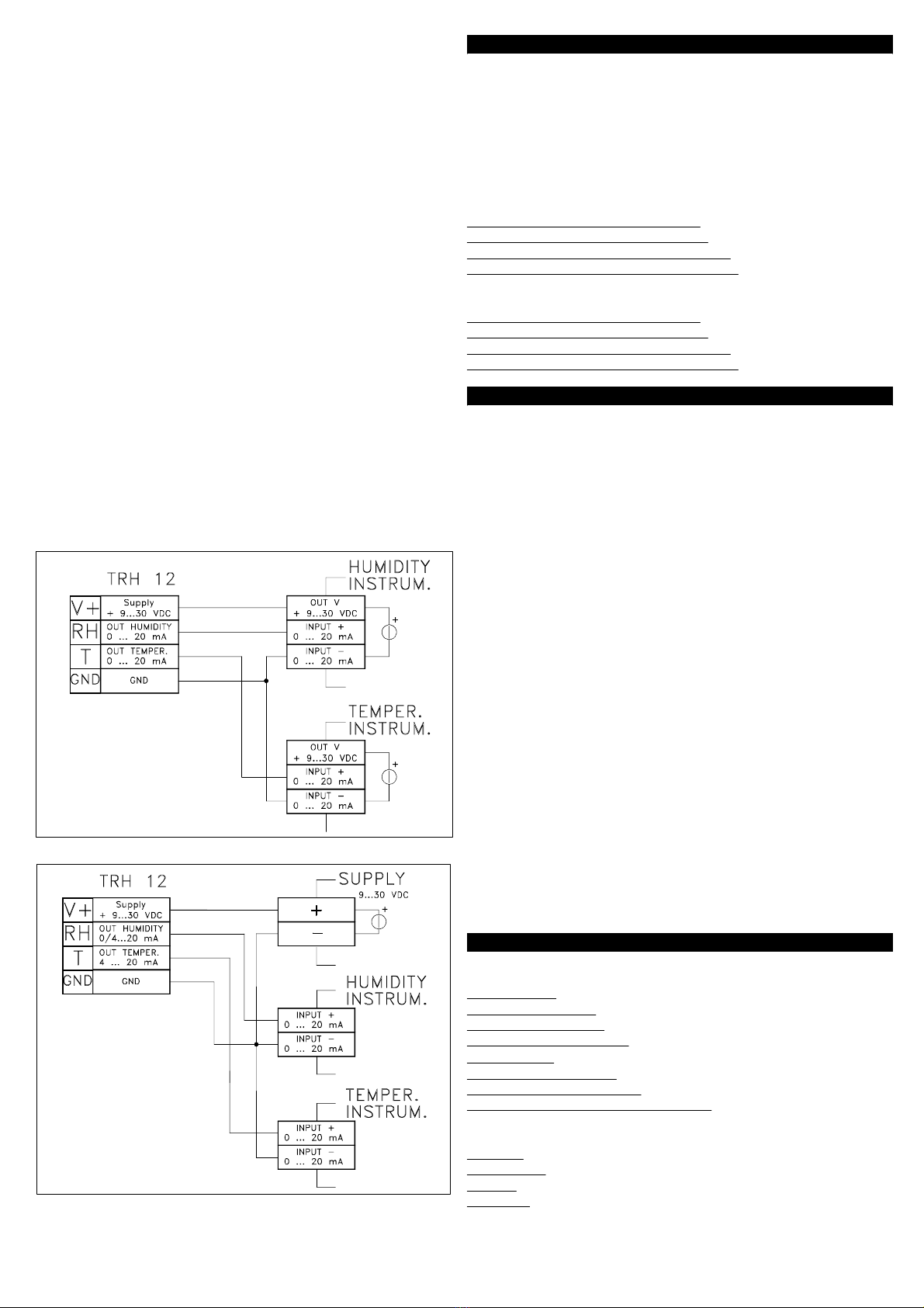
2.4 - ELECTRICAL CONNECTION DRAWING
Wiring diagram with instrument supply :
Wiring diagram with external supply :
3 - OPERATING MODE
The instruments to which the probe has to be connected has to be
provided with a current input 0 ... 20 mA type.
To have a correct measure indication is necessary to set the lower
and upper input limits.
These limits are the corrisponding value to 0 mA (lower limit or
beginning of scale) and 20 mA (upper limit or ending of scale) which
have to be displayed.
See on the operating instructions of the measure instrument the
setting mode of these limits.
The set values for TRH 12 probe are:
Lower limit umidity measure (0 mA) : 0
Upper limit umidity measure (20 mA) : 100
Lower limit temperature measure (0 mA) : -30 (°C) or -22 (°F)
Upper limit temperature measure (20 mA) : 70 (°C) or 158 (°F)
It's possible to use instruments with input 4 ..20 mA, in this case the
limits to set will be:
Lower limit umidity measure (4 mA) : 20
Upper limit umidity measure (20 mA) : 100
Lower limit temperature measure (4 mA) : -10 (°C) or 14 (°F)
Upper limit temperature measure (20 mA) : 70 (°C) or 158 (°F)
4 - PROBLEMS, MAINTENANCE AND WARRANT
Y
4.1 - MEASURE ERRORS
Umidity reading errors can occur if settling time is too short, or be
caused by steam, sprayed water, air drafts, direct exposure to
sunlight, or presence of condesate on the sensor.
To obtain accurate measurements the sensor should be left to settle
in the existing atmosphere for some time.
To reduced the possibility of condesation on the humidity sensor
place the probe in ventilated position and where there is not a quick
and elevation variation of temperature (from cold to warm)
4.2 - CLEANING
It’s raccomanded to clean the box only with a cloth welted with water
or with a detergent neither abrasive nor containing solvents.
Should be necessary to remove the protective cap, do not cause
any mechanical stress to the sensors and absolutely avoid touching
the umidity sensor.
4.3 - WARRANTY AND REPAIRS
The instrument is under warranty against construction vices or
defected material, noticed within 12 months from delivery date.
The warranty is limited to the repairs or to the substitution of the
instrument.
The eventual violation of the instrument or the wrong use and
installation of the product means the automatic decay of the
warranty.
In case of defected instrument, noticed in warranty period or out of
warranty, do contact our sales department to obtain the shipment
authorisation.
The defected product must be shipped to TECNOLOGIC with the
detailed description of the failures found and without any fees or
charge for Tecnologic, safe different agreements.
5 - TECHNICAL DATA
5.1 - ELECTRICAL DATA
Power supply: 9 ... 30 VDC
Power consumption:50 mA MAX
Humidity sensor type: Capacitive
Temperature sensor type: RTD Pt100 (class B)
External load: 250 ΩMAX
Humidity output signal : 0...20 mA (0 ...100 %RH)
Temperature output signal : 0...20 mA (-30 ...70 °C )
Protection class against electric shock: Class III
5.2 - MECHANICAL DATA
Housing: plastic
Dimensions: 80 x 80 mm, depth 52 mm
Weight: 130 g approx.
Mounting: Wall mounting
TECNOLOGIC - TRH 12 - OPERATING INSTRUCTIONS - Vr. 01 - ISTR 05833 - PAG. 2

Connections: 2,5 mm
2
screw terminal block
Recommended connection cable: 4x0,5 or 4x 75 mm
2
Box protection : IP 65
Air filter: Polyethylene
Operating temperature : -30 ... 70 °C
Operating humidity: 0 ... 100 RH%
Storage temperature: -30 ... 80 °C
Maximum workplace pollutant concentration:
380 mg/m
3
100 ppmToluene/Xylen
e
(C6H5CH3)
9 mg/m
3
5 ppmNitrogen Oxides (NOx)
15 mg/m
3
10 ppmHydrogen Sulphide (H2S)
13 mg/m
3
5 ppmSulphur Dioxide (SO2)
7 mg/m
3
5 ppmHydrochloric
A
cid (HCl)
590 mg/m
3
200 ppm2-Butanone (C2H5COCH3)
980 mg/m
3
400 ppmIsopropanol ((CH3)2CHOH)
1,2 mg/m
3
1 ppmFormaldehyde (HCHO)
260 mg/m
3
100 ppmEthylen
e
Glycol ( HOCH2CH2OH
)
1900 mg/m
3
1000 ppmEthanol (C2H5OH)
1400 mg/m
3
400 ppmEthyl
A
cetat
e
(CH3COOC2H5)
25 mg/m
3
10 ppmAcetic Acid (CH3COOH)
1,5 mg/m
3
1 ppmChlorine (Cl2)
1200 mg/m
3
300 ppmPetrol
18 mg/m
3
25 ppm
A
mmonia (NH3)
2400 mg/m
3
1000 ppmAcetone (CH3COCH3)
5.3 - MECHANICAL DIMENSIONS AND FIXING DEVICE [mm]
5.4 - FUNCTIONAL DATA
Humidity measurement range: 0 ... 100 %RH (0...20 mA)
Temperature measurement range: -30 ... 70 °C (0...20 mA)
Humidity overall accuracy : +/- 1,5 % (10...95%RH), +/- 2 % (0...10
/ 95...100 %RH) ; (without pollutant presence, at 23 °C and with an
air speed of 3 m/s)
Additional error with pollutant presence: +/- 2 %RH
Temperature overall accuracy : +/- 0,9 %
Response time : 30 sec. to reach a 63 % of an humidity change (at
23 °C and with an air speed of 3 m/s)
Recovery time after saturation: 90 sec. approx.
Maximum air speed: 20 m/s
Temperature compensation: By Pt100 probe
Compliance: ECC directive EMC 2004/108/CE (EN 61326), ECC
directive LV 2006/95/CE (Instrument operating under 50 VAC and
75 VDC)
TECNOLOGIC - TRH 12 - OPERATING INSTRUCTIONS - Vr. 01 - ISTR 05833 - PAG. 3
Table of contents
Other Tecnologic Measuring Instrument manuals


