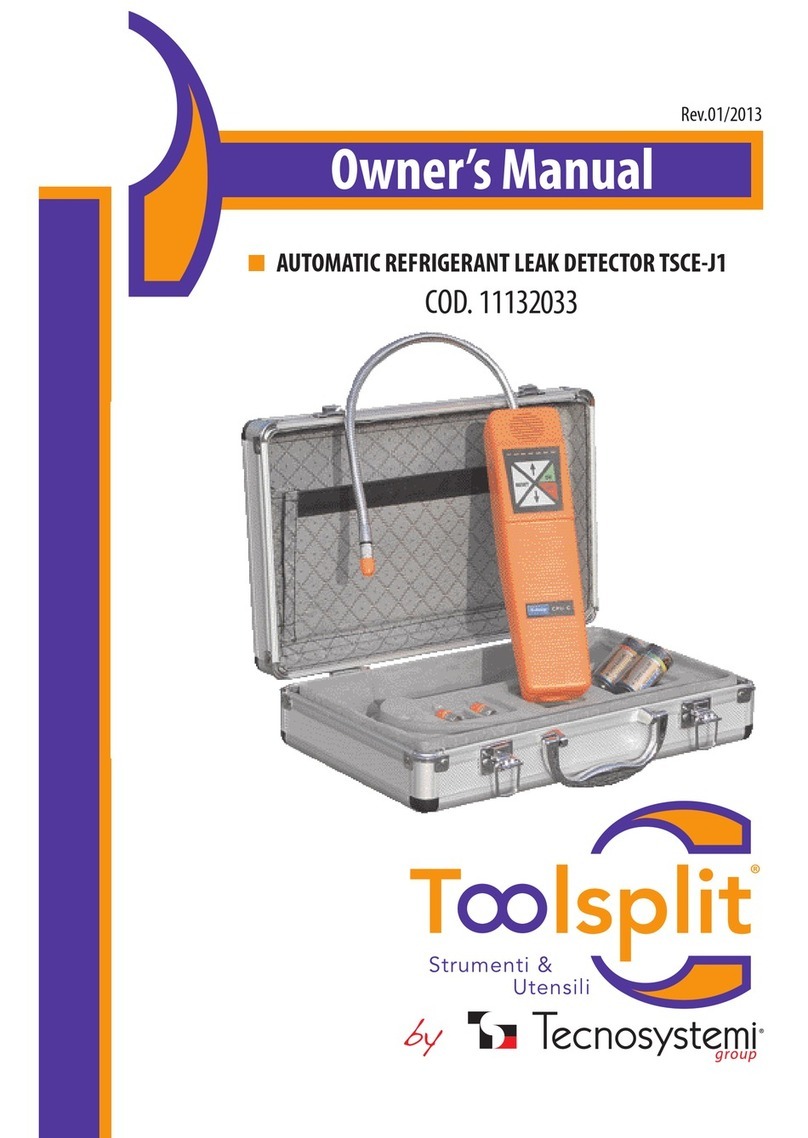
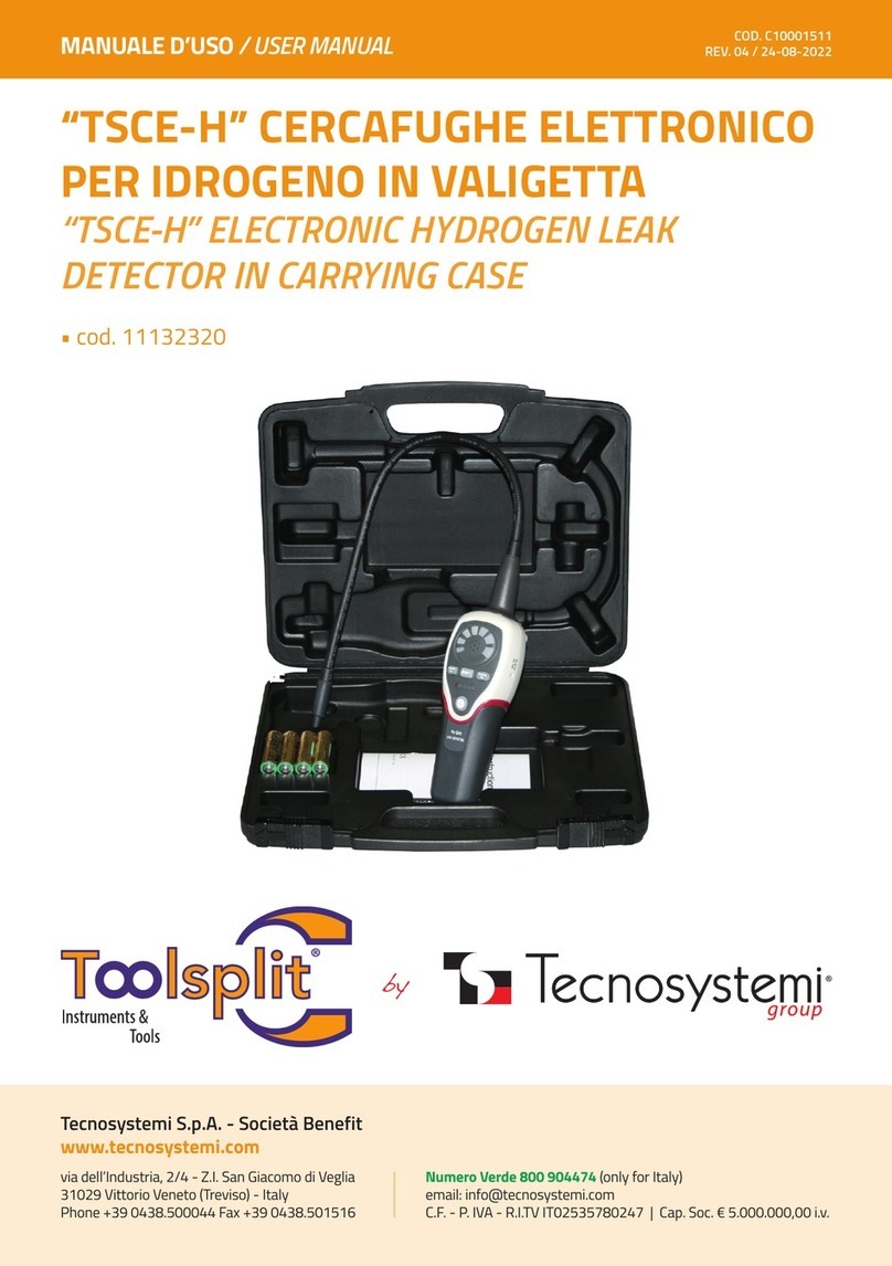
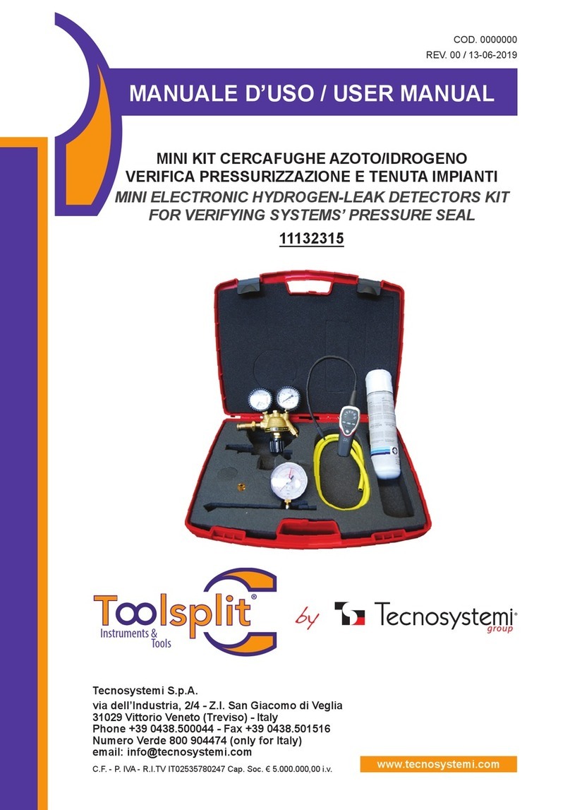
Tecnosystemi Toolsplit TSCE-500 User manual

MANUALE D’USO / USER MANUAL
Tecnosystemi S.p.A. - Società Benefit
www.tecnosystemi.com
via dell’Industria, 2/4 - Z.I. San Giacomo di Veglia
31029 Vittorio Veneto (Treviso) - Italy
Phone +39 0438.500044 Fax +39 0438.501516
Numero Verde 800 904474 (only for Italy)
email: [email protected]
C.F. - P. IVA - R.I.TV IT02535780247 | Cap. Soc. € 5.000.000,00 i.v.
REV. 04 / 24-08-2022
COD. C10001510
“TSCE-500” CERCAFUGHE ELETTRONICO
IN VALIGETTA
“TSCE-500” ELECTRONIC LEAK DETECTOR
IN CARRYING CASE
• cod. 11131121

2
CARATTERISTICHE TECNICHE
/ TECHNICAL FEATURES
• DIMENSIONI (cm): 17x6x3,8
• ALIMENTAZIONE BATT. 2x1,5 V (3 Vdc)
• DURATA BATTERIA: 40 ORE
• SENSIBILITA’: 3g/ANNO CIRCA
• DURATA SENSORE: 30 ORE
• TEMPERATURA DI UTILIZZO: DA 0°C A +50°C
• TEMPO DI RISPOSTA E RESET: IMMEDIATO
• LUNGHEZZA SONDA: 20 CM
• SENSIBILITÀ REGOLABILE SU 5 LIVELLI
• RILEVA TUTTI I REFRIGERANTI ALOGENATI
• COMPLETO DI VALIGETTA
DIMENSIONS (cm): 17x6x3.8
• BATTERY POWER SUPPLY 2x1.5 V (3 VDC)
BATTERY LIFE: 40 HOURS
• SENSITIVITY: 3g/YEAR APPROX.
• SENSOR LIFE: 30 HOURS
• OPERATING TEMPERATURE: 0 °C TO +50 °C
• RESPONSE AND RESET TIME: IMMEDIATE
• PROBE LENGTH: 20 CM
• THERE ARE 5 ADJUSTABLE LEVELS OF SENSITIVITY
• DETECTS ALL HALOGENATED REFRIGERANTS
• INCLUDES CARRYING CASE
Sonda flessibile
Cicalino
Indicatore di perdita
Elemento sensibile
Regolazione sensibilità RESET
ON/OFF
APPLICAZIONI
/ APPLICATION
La serie di rilevatori di perdite può essere usata anche per:
• Rilevare perdite in altri sistemi e contenitori di
stoccaggio/recupero. Risponderà a TUTTI i refrigeranti
alogenati (contenenti cloro o fluoro) Inclusi, ma non
solo:
• CFC come R12,R11, R500.R503 ecc...
• HCFC come R22,R123,R1 24,R502 ecc...
• HFC come R134a,R404a,R125 ecc...
• Rilevare perdite di gas ossido di etilene nelle attività di
sterilizzazione ospedaliere (rileverà il gas di trasporto
alogenato)
• Rilevare SF-6 in interruttori ad alta tensione
• Rilevare la maggior parte di gas che contengono cloro,
fluoro e bromo (gas alogeni)
• Rilevare agenti pulenti utilizzati nel lavaggio a secco,
come il tetracloroetene
• Rilevare gas Halon negli impianti di protezione
antincendio
The leak detector series can also be used for:
• Detecting leaks in other storage/recovery systems and containers. Will respond to ALL halogenated refrigerants (containing
chlorine or fluorine) including, but not limited to:
• CFCs such as R12,R11, R500.R503 etc...
• HCFCs such as R22,R123,R1 24,R502 etc...
• HFCs such as R134a,R404a,R125 etc...
• Detecting ethylene oxide gas leaks in hospital sterilization activities (will detect halogenated carrier gas)
• Detecting SF-6 in high voltage switches
• Detecting most gases that contain chlorine, fluorine and bromine (halogen gases)
• Detecting cleaning agents used in dry cleaning, such as tetrachloroethene
• Detecting Halon gas in fire prevention systems
/ Sensitive element
/ Flexible probe
/ Buzzer
/ Leak indicator
/ Sensitivity adjustment

3
FUNZIONAMENTO DELL’ELEMENTO SENSIBILE
/ OPERATION OF THE SENSITIVE ELEMENT
1. Il sistema di aria condizionata o refrigerazione deve essere riempito con sufficiente refrigerante in modo tale da
avere una pressione di 50 psi quando non è in funzione. A temperature sotto i 15°C, non è possibile rilevare le perdite,
perché non viene raggiunta la giusta pressione.
2. Se la parte testata è contaminata, attenzione a non contaminare la punta della sonda del rilevatore. Se la parte
è particolarmente sporca, o è presente condensa (umidità), deve essere asciugata con un panno asciutto o con aria
compressa. Non utilizzare detersivi o solventi; il rilevatore potrebbe essere sensibile agli ingredienti.
3. Controllare l’intero sistema refrigerante e cercare segni di perdite di lubrificante per aria condizionata, danni e segni
di corrosione su tutte le linee, tubi e componenti. Controllare ogni area con le sonde di rilevamento, così come tutti i
raccordi, tubi a raccordo di linea, comandi del refrigeratore, porte di servizio con tappi, zone brasate o saldate e zone
intorno a punti di attacco, e dispositivi di blocco sulle linee e componenti.
4. Seguire sempre il sistema refrigerante in un percorso continuo in modo da non mancare nessuna potenziale
perdita. Se viene trovata una perdita, continuare sempre a testare il resto del sistema.
5. Per ogni area controllata, muovere la sonda attorno all’area ad una velocità non superiore a 25-55 mm al secondo
(1-2 in/secondo), e ad una distanza di non più di 5 mm dalla superficie. Movimenti lenti e ravvicinati della sonda
aumentano le probabilità di trovare una perdita .Qualsiasi variazione nel suono dell’allarme indica una perdita.
1. The air conditioning or refrigeration system must be filled with enough refrigerant to reach a pressure of 50 psi when not in
operation. At temperatures below 15°C, it is not possible to detect leaks, because the right pressure is not reached.
2. If the tested part is contaminated, make sure that the probe tip of the detector is not contaminated as well. If the part is
especially dirty, or there is condensation (moisture), it must be dried with a dry cloth or compressed air. Do not use detergents
or solvents; the detector may be sensitive to the ingredients contained in such products.
3. Check the entire refrigerant system and look for signs of air conditioning lubricant leakage, damage and signs of corrosion
on all the lines, pipes and components. Use sensing probes to check each area, all fittings, line fitting pipes, refrigerant
controls, service doors with plugs, brazed or welded zones and zones around coupling points, as well as locking devices on
lines and components.
4. Always follow the refrigerant system in a continuous path so as not to miss any potential leak. If a leak is found, carry on
testing the rest of the system.
5. For each checked area, move the probe around the area at a speed of not more than 25-55 mm per second (1-2 in/second),
and at a distance from the surface not exceeding 5 mm. Slow and close-sequence movements of the probe increase the
chances of finding a leak. Any change in the sound of the alarm indicates a leak.

4
6 . Una perdita apparente deve essere verificata almeno una volta nel modo seguente:
a) Soffiare aria compressa nella zona della sospetta perdita, se necessario, e ripetere il controllo dell’area. In caso di
una perdita di grandi dimensioni, soffiare aria compressa nell’area aiuta a localizzare l’esatta posizione della perdita.
b) Prima di tutto muovere la sonda all’aria aperta e reimpostare l’apparecchio. Quindi tenere la punta della sonda il più
vicino possibile alla presunta fonte della perdita e muoverla lentamente fino alla conferma della perdita.
7. A seguito di qualsiasi intervento di ricerca perdite che interessi il sistema di condizionamento o di refrigerazione, si
consiglia di effettuare una prova di tenuta sulle parti interessate alla riparazione.
6. An apparent leak must be verified at least once, as follows:
a) Blow compressed air into the area where there is a suspected leak, if necessary, and repeat the check. In the event of an
extensive leak, blowing compressed air into the area helps identify the exact location of the leak.
b) First, move the probe outdoors and reset the equipment. Then hold the tip of the probe as close as possible to the presumed
source of the leak and move it slowly until the leak is confirmed.
7. Following any leak research involving the air conditioning or refrigeration system, we recommend carrying out a leak test
on the parts subjected to repair work.
Premere il pulsante ON/OFF, il cercafughe entra in modalità autodiagnosi, i 7 LED lampeggeranno per 5 secondi e le
luci rosse gradualmente si spegneranno per poi entrare in normale stato di funzionamento.
Premere il tasto “regolazione sensibilità” si entra nella più alta condizione di sensibilità. Nel frattempo sulla sinistra
l’indicatore batteria visualizzerà la corretta carica della stessa (LED colore verde), contemporaneamente il segnale
acustico indicherà le concentrazioni correnti come livello zero, e il cercafughe è in condizione di lavoro.
FUNZIONAMENTO
/ OPERATION
Press the ON/off button: the leak detector enters the self-diagnosis mode, the 7 LEDs will flash for 5 seconds, and the red
lights will gradually turn off and then enter the normal operating mode.
Press the “sensitivity adjustment” button to enter the highest sensitivity condition. Meanwhile, on the left, the battery indicator
will display the correct charge (green LED); at the same time the acoustic signal will indicate the current concentrations as
zero, and the leak detector is in working condition.
Regolare la sensibilità quando il cercafughe è acceso, la sua sensibilità predefinita è compresa tra 4 e 5 livelli senza
indicatore LED. Per regolare il livello di sensibilità, premere il tasto “regolazione sensibilità”, e il livello di sensibilità
verrà mostrato sull’indicatore LED.
La velocità di segnale acustico cambia con il livello di sensibilità impostato. A livello di sensibilità basso il tono è lento,
e ad alto livello di sensibilità con il tono rapido.
REGOLAZIONE DELLA SENSIBILITÀ
/ SENSITIVITY ADJUSTMENT
Adjust the sensitivity when the leak detector is on; its default sensitivity is between levels 4 and 5 without LED indicator. To
adjust the sensitivity level, press the “sensitivity adjustment” button: the sensitivity level will be shown on the LED indicator.
The speed of the acoustic signal changes with the set sensitivity level. When the sensitivity level is low, the tone is slow; it is
fast when the sensitivity level is high.

5
OPERAZIONE DI RIPRISTINO
/ RESETTING OPERATION
Premere il tasto RESET per 2 secondi per confermare l’operazione di ripristino.
Il cercafughe viene resettato ed in questa condizione il livello di refrigerante presente sulla punta viene ignorato,
questo permette all’utente la regolazione dello “zero” rispetto alla perdita (concentrazione più elevata).
In questo modo, il cercafughe otterrà la massima sensibilità. Il ripristino del cercafughe, fatta in ambiente senza alcun
refrigerante presente (aria fresca), fa in modo che qualsiasi livello di perdita sopra lo zero sia rilevato.
Press the RESET button for 2 seconds to confirm the resetting operation.
The leak detector is reset: in this condition, the level of refrigerant present on the tip is ignored, which allows the user to adjust
the “zero” with respect to the leak (higher concentration).
In this way, the leak detector will obtain the maximum sensitivity. When the leak detector is reset in an environment without
any refrigerant (fresh air), any leak whose level is above zero is detected.
PROCEDURA CONSIGLIATA
/ RECOMMENDED PROCEDURE
1. Alzare la sensibilità, solo quando una perdita non può essere rilevata; abbassare la sensibilità solo quando il ripri-
stino del unità non consente di azzerare la sensibilità stessa.
2. Nelle zone fortemente contaminate, resettare il rivelatore in modo che ignori le perdite presenti. Non spostare la
sonda durante il ripristino.
3. In zone ventose, anche una forte perdita può essere difficile da individuare. In questa condizione, è meglio scher-
mare la zona in cui si suppone ci sia la perdita.
4. Tenere presente che il cercafughe può segnalare una perdita anche se l’elemento sensibile entra in contatto con
solventi. Evitare di entrare in contatto con questi, mentre si effettua una ricerca della perdita.
Nel tempo l’elemento sensibile perderà la sua precisione. E‘ difficile prevedere esattamente quando sostituirlo, poi-
ché la sua longevità è direttamente correlata alle condizioni e frequenza di utilizzo. L’elemento sensibile dovrebbe
essere sostituito quando suona il cicalino o diventare instabile in un ambiente con aria pulita.
SOSTITUZIONE DELL’ELEMENTO SENSIBILE
/ REPLACING THE SENSITIVE ELEMENT
Over time, the sensitive element will lose its accuracy. It is difficult to predict exactly when to replace it, as its lifespan is
directly related to the conditions and frequency of use. The sensitive element should be replaced when the buzzer sounds, or
when it becomes unstable in a clean air environment.
1. Increase the sensitivity only when a leak cannot be detected; lower the sensitivity only when resetting the unit does not
allow resetting the sensitivity itself.
2. In heavily contaminated areas, reset the detector so that it ignores any leaks. Do not move the probe during resetting
operations.
3. In windy areas even an heavy leak may be difficult to spot. In this condition, it is best to shield the area where the leak is
supposed to be.
4. Keep in mind that the leak detector can signal the presence of a leak also when the sensitive element comes into contact
with solvents. Avoid coming into contact with these products while looking for a leak.

6
SMALTIMENTO
DISPOSAL
GARANZIA
WARRANTY
Alla fine della sua vita utile il prodotto non deve essere smaltito insieme ai rifiuti urbani. Può essere
consegnato presso gli appositi centri di raccolta differenziata predisposti dalle amministrazioni
comunali, oppure presso i rivenditori che forniscono questo servizio. Per rimarcare l’obbligo di smaltire
separatamente gli elettrodomestici, sul prodotto è riportato il marchio del contenitore di spazzatura
mobile barrato.
At the end of its useful life, the product must not be disposed of with household waste. It can be deposited at
a dedicated recycling centre run by local councils, or at retailers who provide such a service. To highlight the
requirement to dispose of household electrical items separately, there is a crossed-out waste paper basket
symbol on the product.
La garanzia ha durata di 1 (uno) anno a decorrere dalla data di consegna indicata sul d.d.t (bolla). E’ prevista altresì
l’estensione d’ufficio, a titolo gratuito, per il secondo anno (due anni complessivi di garanzia) con decorrenza sempre
dalla data indicata nel d.d.t di consegna (bolla).
L’azienda fornitrice garantisce la qualità dei materiali impiegati e la corretta realizzazione dei componenti. La garanzia
copre difetti di materiale e di fabbricazione e si intende relativa alla fornitura dei pezzi in sostituzione di qualsiasi
componente che presenti difetti, senza che possa venir reclamata alcuna indennità, interesse o richiesta di danni.
La garanzia non copre la sostituzione dei componenti che risultano danneggiati per:
• trasporto non idoneo;
• installazione non conforme a quanto specificato in questo manuale di installazione uso e manutenzione;
• la non osservanza delle specifiche tecniche di prodotto;
• quant’altro non riconducibile a vizi originari del materiale o di produzione a condizione che il reclamo del cliente
sia coperto dalla garanzia e notificato nei termini e modalità richiesta dal fornitore, lo stesso si impegnerà, a sua
discrezione, a sostituire o riparare ciascun prodotto o le parti di questo che presentino vizi o difetti.
The warranty is valid for 2 (two) years from the delivery date indicated on the delivery note / waybill.
The supplier company guarantees the quality of the materials used and the correct construction of the components. The
warranty covers defects in materials and manufacturing defects and refers to the supply of spare parts of any components
featuring defects, without any compensation, interest or claim for damages.
The warranty does not cover the replacement of components damaged due to:
incorrect transportation;
installation not compliant with that specified in this installation, use and maintenance manual;
non-observance of product technical specifications;
Anything else that is not linked to original faults of the material or production provided that the
customer complaint is covered by the guarantee and a claim is made within the time limit and
in the way requested by the supplier, the same supplier will commit, at their own discretion,
to replace or repair any product or part of product showing signs of faults or defects.

7
NOTE
NOTES

·
W
E
A
R
E
A
B
E
N
E
F
I
T
C
O
M
P
A
N
Y
·
W
E
A
R
E
A
B
E
N
E
F
I
T
C
O
M
P
A
N
Y
·
W
E
A
R
E
A
B
E
N
E
F
I
T
C
O
M
P
A
N
Y
Tecnosystemi S.p.A. Società Benefit
www.tecnosystemi.com
via dell’Industria, 2/4 - Z.I. San Giacomo di Veglia
31029 Vittorio Veneto (Treviso) - Italia
Tel +39 0438.500044 - Fax +39 0438.501516
email: [email protected]
C.F. - P. IVA - R.I.TV IT02535780247
Cap. Soc. € 5.000.000,00 i.v.
800 904474
ONLY FOR ITALY
WATCH OUR
INSTITUTIONAL VIDEO
II
SS
OO
9
9
0
0
0
0
1
1
S
S
Y
Y
S
S
T
T
E
E
MM
CC
EE
RR
TT
II
FF
II
C
C
A
A
T
T
I
I
O
O
N
N
This manual suits for next models
1
Table of contents
Other Tecnosystemi Security Sensor manuals

Tecnosystemi
Tecnosystemi Toolsplit TSCE-H User manual

Tecnosystemi
Tecnosystemi Toolsplit TSCE-300 User manual

Tecnosystemi
Tecnosystemi TSCE-J1 User manual

Tecnosystemi
Tecnosystemi Toolsplit TSCE-100 User manual

Tecnosystemi
Tecnosystemi Toolsplit TSCE-900 User manual

Tecnosystemi
Tecnosystemi Toolsplit 11132315 User manual
Popular Security Sensor manuals by other brands

Satel
Satel AQUA LUNA quick start guide

hager
hager TX510 User instructions

Tense
Tense Motivity Technical documentation

PCB Piezotronics
PCB Piezotronics IMI SENSORS 640B61/015BZ Installation and operating manual

STEINEL PROFESSIONAL
STEINEL PROFESSIONAL IR Quattro MICRO KNX Information

Visonic
Visonic CLIP-4N installation instructions