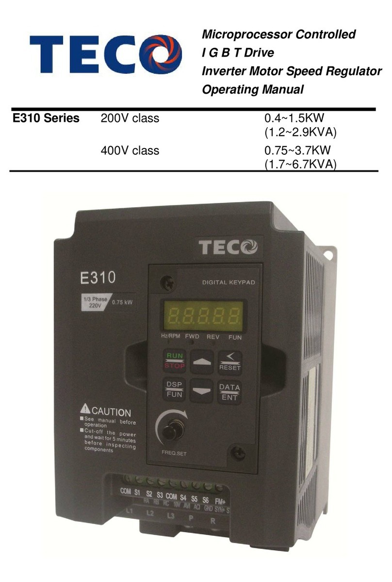
TECO JNEV-202~203-H1 User manual

Microprocessor Controlled
IGBT Drive
Inverter Motor Speed Regulator
Operating Manual
EV Series 110V 0.2∼0.75KW
(0.2∼1HP)
220V 0.2∼2.2KW
(0.2∼3HP)
440V 0.75∼2.2KW
(1∼3HP)
This manual may be modified when necessary because of improvement of the product, modification,
or changes in specifications, This manual is subject to change without notice.
Distributor
Ver:03 2006.05
10F., No.3-1, Yuancyu St., Nangang District,
Taipei City 115, Taiwan
Tel :+886-2-6615-9111
Fax :+886-2-6615-0933
http://www.teco.com.tw

i
Quick Start Guide
This guide is to assist in installing and running the inverter to verify that the drive and motor
are working properly. Starting, stopping and speed control will be from the keypad. If your
application requires external control or special system programming, consult the 7300EV
Instruction Manual supplied with your inverter.
Step 1 Before starting the inverter
Please refer to chapter one (Preface) and chapter two (Safety Precautions) of the 7300EV
Instruction Manual. Verify drive was installed in accordance with the procedures as
described in chapter three (Environment description and installation). If you feel this was
abnormal, do not start the drive until qualified personnel have corrected the situation.
(Failure to do so could result in serious injury.)
•Check inverter and motor nameplates to determine that they have the same HP and voltage
ratings. (Ensure that full load motor amps do not exceed that of the inverter.)
•Remove the terminal cover to expose the motor and power terminals.
a. Verify that AC power is wired to L1(L), L2, and L3(N) .
b. Verify that Motor leads are connected to T1, T2, and T3 .
c. IF brake module is necessary, please connect terminal voltage of the braking unit to +
and -of the inverter.
Step2 Apply power to the drive.
Apply AC power to the drive and observe operator. Three 7-segment display should show
power voltage for 3~5 seconds and then show Frequency Command, factory sets 5.00.
(Frequency Command of 7-segment display should be flashed all the time.)
Power Indicator

ii
Step3 Check motor rotation without load.
zPress RUN Key. 7-segment Display will indicates 00.0to 05.0. Such value is the frequency
output value.
zCheck the operation direction of the motor.
IF the direction of the motor is incorrect:
Press STOP Key, turn off the AC power supply. After Power indicator LED is off,
change over theT1 and T2.
Supply the power again, then check the motor direction.
zPress STOP key.
Step4 Check full speed at 50Hz/60Hz
zChange the frequency with ¿,Àarrow mark , please press DATA/ENTER after setting
frequency.
zSet frequency to 50Hz/60Hz according to the above regulations.
zPress RUN Key, inspect the motor operation as motor accelerates to full load.
zPress STOP Key, inspect the motor operation as motor deceleration.
Step5 Other settings
As for other function, please refer to 7300EV user manual.
Set acceleration time ………………………………… P. 4-9
Set deceleration time ………………………………… P. 4-9
Set upper frequency limit ….………………………... P. 4-12
Set lower frequency limit ……………………………. P. 4-12
Set motor rated current ………………………………P. 4-30
Set control mode (Vector, V/F) ………………………P. 4-26
Step6 vector Mode Settings
When the EV inverter is set to run in Vector Mode (C14=000), the motor parameters needs to
be set. The required in formation should be readily available on the nameplate of the motor.
(Motor kw=0.75 ¯HP)
The parameters to set for vector operation ave:
Motor Rated Current (Amps) (F43) See page 4-23
Motor Rated Voltage (Volts) (F44) See page 4-23
Motor Rated Frequency (Hz) (F45) See page 4-23
Motor Rated Power (KW) (F46) See page 4-23
Motor Rated Speed (RPM) (F47) See page 4-23
Additional Vector Mode Settings to adjust for optimum operations are:
Torque boost gain (F48) See page 4-23
Slip compensation gain (F49) See page 4-24
Low Frequency Voltage Compensation (F50) See page 4-25

iii
7300EV user manual
Table of Contents
Tutorial........................................................................................................................ i
Content...................................................................................................................... iii
Preface..................................................................................................................... 0-1
Preface.................................................................................................................... 0-1
Product inspection .................................................................................................. 0-1
Chapter 1 Safety precautions............................................................................... 1-1
1.1 Operation precautions ....................................................................................... 1-1
1.1.1 Before power up ........................................................................................ 1-1
1.1.2 During power up ....................................................................................... 1-2
1.1.3 Before operation........................................................................................ 1-2
1.1.4 Leakage current ........................................................................................ 1-2
1.1.5 During operation....................................................................................... 1-3
1.1.6 Useable environment ................................................................................. 1-3
Chapter 2 Model definition.................................................................................. 2-1
Chapter 3 Mounting and installation of the JNEV drive................................ 3-1
3.1 Environment ..................................................................................................... 3-1
3.2 Mounting and installation.................................................................................. 3-3
3.3 Wiring rules ...................................................................................................... 3-7
3.3.1 Notice for wiring........................................................................................ 3-7
3.3.2 Suitable MC, MCCB, fuse and wire specification ....................................... 3-9
3.3.3 Precautions for peripheral applications.................................................... 3-10
3.4 Inverter specification....................................................................................... 3-14
3.4.1 Basic specifications.................................................................................. 3-14
3.4.2 General specifications.............................................................................. 3-15
3.5 7300EV wiring diagram................................................................................... 3-17
3.6 Description of inverter terminal....................................................................... 3-18
3.7 Dimension ....................................................................................................... 3-21
3.8 Installation and design considerations.............................................................. 3-24

iv
Chapter 4 Programming instructions & parameter list.................................. 4-1
4.1 Keypad description............................................................................................ 4-1
4.1.1 Keypad description.................................................................................... 4-1
4.1.2 Operation instruction of the keypad........................................................... 4-1
4.2 Parameter functions list..................................................................................... 4-3
4.3 Parameter functions description....................................................................... 4-10
Chapter 5 Trouble shooting and maintenance.................................................. 5-1
5.1 Trouble indication and corrective action............................................................ 5-1
5.1.1 Fault/Error display and diagnostics ........................................................... 5-1
5.1.2 Set up& interface errors ............................................................................ 5-4
5.1.3 Keypad operation error description........................................................... 5-5
5.2 General functional troubleshooting.................................................................... 5-6
5.3 Troubleshooting flowcharts 7300EV series......................................................... 5-7
5.4 Routine and periodic checks............................................................................. 5-13
Chapter 6 Peripherals components..................................................................... 6-1
6.1 Input side AC reactor ........................................................................................ 6-1
6.2 EMC filter......................................................................................................... 6-1
6.3 Option card....................................................................................................... 6-6
6.3.1 RS-485 option card.................................................................................... 6-6
6.3.2 RS-232 option card.................................................................................... 6-7
6.3.3 Program copy option card ......................................................................... 6-8
6.3.4 Remote keypad.......................................................................................... 6-9
6.3.5 2 IN/1OUT card....................................................................................... 6-10
6.3.6 PDA link ................................................................................................. 6-11
Appendix 1 7300EV inverter parameter setting list........................... Appendix 1

v
Figure index
Figure 3-1 Panel and enclosure arrangement for drives............................................... 3-1
Figure 3-2 Mounting and clearance requirements........................................................ 3-1
Figure 3-3 Din rail mounting of the JNEV Drive ......................................................... 3-2
Figure 3-4 Side-by-side mounting of the JNEV Drive................................................... 3-2
Figure 3-5 NEMA 4 mounting instructions.................................................................. 3-4
Figure 3-6 NEMA 4 wiring diagram............................................................................ 3-4
Figure 3-7 M/N XX-YYY-N4S (115,230V model) connection diagram.......................... 3-5
Figure 3-8 M/N XX-YYY-N4 (115,230V model) connection diagram............................ 3-6
Figure 3-9 Typical installation schematic....................................................................3-10
Figure 3-10a Installation examples.............................................................................3-11
Figure 3-10b Installation examples using a filter.........................................................3-11
Figure 3-10c Installation examples with adjacent signal conductors............................3-11
Figure 3-11 Grounding filtered units..........................................................................3-12
Figure 3-12 Processing the ends of twisted pair tables.................................................3-12
Figure 3-13 Grounding example, multiple drives........................................................3-12
Figure 3-14 EV wiring diagram..................................................................................3-17
Figure 3-15 Power terminal locations.........................................................................3-18
Figure 3-16 Signal terminal locations .........................................................................3-19
Figure 3-17 EV drive frame 1 dimensions...................................................................3-21
Figure 3-18 EV drive frame 2 dimensions...................................................................3-22
Figure 3-19 EV drive IP65 (switch) frame 1 dimensions..............................................3-23
Figure 3-20 EV drive IP65 (no switch) frame 1 dimensions.........................................3-23
Figure 3-21 Common bus configurations....................................................................3-24
Figure 4-1 Keypad layout............................................................................................ 4-1
Figure 4-2 Keypad operations sequence....................................................................... 4-1
Figure 4-3 Wiring details
a. Fwd/stop-reverse/stop wiring detail ....................................................4-11
b. Run/stop-forward/reverse wiring detail...............................................4-11
c. 3-wire run/stop detail .........................................................................4-11
Figure 4-4 Control method sequences.........................................................................4-12
Figure 4-5 Frequency limits .......................................................................................4-12
Figure 4-6 Acceleration/deceleration prohibit.............................................................4-15
Figure 4-7 AIN gain & bias setting examples..............................................................4-16
Figure 4-8 Frequency detection
a. Frequency Reached (F21/C46=1) .........................................................4-17
b. Frequency Reached (F21/C46=2) .........................................................4-18
c. Frequency Reached (F21/C46=3) .........................................................4-18
d. Frequency Reached (F21/C46=4) .........................................................4-19

vi
Figure 4-9 Output current detection...........................................................................4-19
Figure 4-10 DC injection braking...............................................................................4-21
Figure 4-11 Output torque capacity ...........................................................................4-23
Figure 4-12 Slip compensation ...................................................................................4-23
Figure 4-13 Low frequency voltage compensation.......................................................4-24
Figure 4-14 V/F patterns
a. User configured V/F pattern...............................................................4-26
b. Pre configured V/F pattern.................................................................4-27
Figure 4-15 V/Hz curves with varying base voltages ...................................................4-28
Figure 4-16 PID flow control diagram........................................................................4-30
Figure 4-17 Sleep/wake mode.....................................................................................4-31
Figure 4-18 Communication error timing pattern.......................................................4-35
Figure 5-1 General troubleshooting flowchart............................................................. 5-7
Figure 5-2 OC, OL fault troubleshooting..................................................................... 5-9
Figure 5-3 OV, LV fault troubleshooting....................................................................5-10
Figure 5-4 Drive running troubleshooting diagnostics ................................................5-11
Figure 5-5 Motor overload / overheating diagnostics ..................................................5-12
Figure 5-6 Uneven speed operation diagnostics...........................................................5-12
Figure 6-1 External filter dimensions
a. JNFS21017-20.8-07................................................................................ 6-3
b. JNFS21019-8.9-07 ................................................................................. 6-3
c. JNFS21015-22-07.................................................................................. 6-4
d. JNFS21016-15-07.................................................................................. 6-4
e. JNFS 20858-7-07................................................................................... 6-5
Figure 6-2 JNSIF-485 module ..................................................................................... 6-6
Figure 6-3 JNSIF-485 wiring diagram......................................................................... 6-6
Figure 6-4 RS232 option card
a. JNSIF-232 cable.................................................................................... 6-7
b. JNSIF-232 wiring diagram.................................................................... 6-7
Figure 6-5 Program copy unit
a. JNSIF-MP module ................................................................................ 6-8
b. JNSIF-MP wiring diagram.................................................................... 6-8
Figure 6-6 Remote keypad module
a. JNSDOP remote keypad.........................................................................6-9
b. Remote keypad wiring diagram..............................................................6-9
Figure 6-7 Input/output expansion card
a. JNSIF-IO card.....................................................................................6-10
b. JNSIF-IO wiring diagram ....................................................................6-10

Preface
0-1
Preface
Preface
To extend the performance of the product and ensure personnel safety, read this manual thoroughly
before using the inverter. Should there be any problem in using the product that can not be solved with
the information provided in the manual, contact your nearest TECO distributor or sales representative
who will be willing to help you.
※Precautions
The inverter is an electrical product. For your safety, there are symbols such as “Danger”, “Caution” in
this manual as a reminder to pay attention to safety instructions on carrying, installing, operating, and
checking the inverter. Be sure to follow the instructions for highest safety.
Indicates a potential hazard that causes death or serious personal injury
if misused
Indicates that the inverter or the mechanical system might be damaged if
misused
Danger
zDo not touch any circuit boards or parts while the charging indicator is still lit after
turning the power off.(the light will fade after approximately 5 minutes.)
zDo not connect any wires when the inverter is powered. Do not check parts and signals on
circuit boards when the inverter is in operation.
zDo not disassemble the inverter nor modify any internal wires, circuits, or parts.
zGround the ground terminal of the inverter properly, for 200V class ground to 100 Ωor
below, 400v class ground to 10Ωor below.
Product Inspection
TECO’s inverters have all passed the function test before delivery. Please check the following
when you receive and unpack the inverter:
zThe model and capacity of the inverter is the same as those specified on your order.
zIs there any damage caused by transportation. If so, do not apply the power.
Contact TECO’s sales representatives if any of the above problems happened.
Caution
zDo not perform a voltage test on parts inside the inverter. High voltage can destroy these
semiconductor parts.
zDo not connect T1 (U), T2 (V), and T3 (W) terminals of the inverter to any AC input power
source.
zCMOS ICs on the inverter’s main board are sensitive to static electricity. Do not touch the
main board.
Danger
Caution

Chapter 1 Safety Precautions
1-1
Chapter 1 Safety Precautions
1.1 Operation Precautions
1.1.1 Before Power Up
Caution
The line voltage applied must comply with the inverter’s specified input voltage.(See the
nameplate)
Danger
Make sure the main circuit connections are correct. L1(L), L2, and L3(N) are power-input
terminals and must not be confused with T1, T2 and T3. Otherwise, inverter damage can
result.
Caution
zTo avoid the front cover from disengaging, or other damge do not carry the inverter by its
covers. Support the drive by the heat sink when transpoting.Improper handling can damage
the inverter or injure personnel and should be avoided.
zTo avoid fire, do not install the inverter on a flammable object. Intall on nonflammable objects
such as metal.
zIf several inverters are placed in the same control panel, provide heat removal means to
maintain the temperature below 50oC to avoid overheat or fire.
zWhen removing or installing the LCD operator, turn the power off first, and follow the LCD
instructions in the diagram to avoid operator error or no display caused by bad connections.
Warning
This product complies with IEC 61800-3, with built-in Filter in an unrestricted distribution
and with use of external filter in restricted distribution. Under some environmentswith
electric-magnetic interruption, product should be tested before used.

Chapter 1 Safety Precautions
1-2
1.1.2 DuringPowerup
Danger
zThe inverter still has control power immediately after power loss. When the power is re-
supplied, the inverter operation is controlled by F41.
zThe inverter operation is controlled by F04 and C09 and the status of (FWD/REV RUN
switch) when power is re-supplied. (F39 /F40) Power loss ride through / Auto reset after
fault).
1. When F04=000, the inverter will not auto restart when power is re-supplied.
2. When F04=001 and operation switches (FWD/REV RUN) is OFF, the inverter will not
auto restart when power is re-supplied.
3. When F04=001and operation switch ON and C09=000, the inverter will auto restart
when power is re-supplied. Please turn OFF the run ( start) switch to avoid damage to
machine and injury to personnel before the power is re-supplied.
zWhen C09=000 (direct start on power up), please refer to the description and warning for
C09 (Page 4-27) to verify the safety of operator and machine.
1.1.3 Beforeoperation
Caution
Make sure the model and inverter capacity match the F00 setting (Page 4-12).
1.1.4 Leakage current
Warning
Warning! EV series built in Filter type leakage current can exceed the IEC standard limit
of 3.5mA. Please ground the inverter as shown in figures 3.5 and 3.6.
Operation with ungrounded supplies:
1. Filtered inverters CANNOT be used on ungrounded supplies.
2. Unfiltered inverterscan be used on ungrounded supplies. If any output phase is shorted to
ground, the inverter may trip with OC.(over current trip)
Operation with Residual Current Device(RCD):
1. Afiltered inverter with the trip limit of the RCD is 300mA
2. The neutral of the supply is grounded, as is the inverter.
3. Only one inverter is supplied from each RCD.

Chapter 1 Safety Precautions
1-3
1.1.5 Duringoperation
Danger
Do not connect or disconnect the motor while inverter is operating the motor. The inverter and the
disconnect device can sustain damage from high levelsof switch-off current transients.
Danger
zTo avoid electric shock, do not take the front cover off while power is on.
The motor will restart automatically after stop when auto-restart function is enabled. In this case, care
must be taken while working around the drive and associated equipment .
zNote: The operation of the stop switch is different than that of the emergency stop switch.
The stop switch has to be activated to be effective. Emergency stop has to be de-activated
to become effective.
Caution
zDo not touch heat-generating components such as heat sinksand brake resistors.
zThe inverter can drive the motor from low speed to high speed. Verify the allowable speed ranges of
the motor and the associated machinery.
zNote the settings related to the braking unit.
zDo not check signals on circuit PCB while the inverter is running.
Caution
Allow a minimum of 5 minutes power down before attempting to disassemble or check the
components within the drive.
1.1.6 Useable environment
Caution
When the inverter top dust cover has been removed the drive can be installed in a non-
condensing environment with temperature ranging between –10oC to +50 oC and relative
humidities of 95% or less, but the environment should be free from water and metal dust.

Chapter 2 Model description
2-1
Chapter 2 Model description
Inverter model Model:JNEV-201-H1
Input power I/P: AC 1 PH
200-240V 50/60Hz
O/P: AC3PH 0~264V
Output power 1.6KVA 4.2A
TECO ELECTRIC&MACHINERY CO.,LTD.
JNEV -2P5 - H 1FN4S
Series:
Input
voltage : Max suitable motor
capacity: SPEC Power supply Noise filter Enclosure
1: 110V P2: 0.25 HP H: standard 1:single phase Blank : none
2: 230V P5: 0.5 HP 3:three phase F: built-in
N4S:IP65 with water
and dust proof switch
4: 460V 01: 1.0 HP
02: 2.0 HP
N4:IP65 without water
and dust proof switch
03: 3.0 HP Blank: IP20

Chapter 3 Environment description and installation
3-1
Chapter 3 Mounting and installation of the JNEV drive
3.1Environment
The environment will directly affect the proper operation and the life of the inverter, so install
the inverter in an environment that complies with the following conditions:
zAmbient temperature: 14~122 deg F (-10 to 50 deg C)
zAvoid exposure to rain or moisture. zAvoid direct sunlight.
zAvoid smoke and salinity. zAvoid corrosive liquid and gas.
zAvoid dust, lint fibers, and metal filings. zKeep away from radio active and
flammable materials.
zAvoid electromagnetic interference (soldering machines, power machine).
zAvoid vibration (stamping, punchpress). Add a vibration-proof pad if the situation can not
be avoided.
zIf several inverters are placed in the same control panel, provide heat remoual means to
maintain the temperature below 50oC. See figure 3-1 for proper drive arrangment.
(Correct ) (Incorrect ) (Correct) (Incorrect)
Figure 3-1 Panel and enclosure arrangement for drives
zPlace the front side of the inverter outward and the top upward to improve heat dissipation.
(A)Front view (B)Side view
Figure 3-2 Mounting and clearance requirements
Panel
Enclosure
fan fan
Enclosure
JNEV

Chapter 3 Environment description and installation
3-2
zAll JNEV drives in IP-20 Enclosures can be DIN-RAIL mounted as shown below.
Figure 3-3 Din Rail Mounting of the JNEV Drive
zAll JNEV Drives in IP-20 enclosures can be mounted side-by-side as shown below. (ambient
temperature below 122˚F)(50 oC).
Figure 3-4 Side-by-side Mounting of the JNEV Drive

Chapter 3 Environment description and installation
3-3
3.2 Mounting and installation
Do not use the inverter in an environment with the following conditions:
Direct sunlight Corrosive gas and liquid Oil
Salt Wind, rain, and water
drops may get into Iron filings, dust
Extreme low temperature
Electromagnetic wave
and ultra hi
g
h wave Radioactive materials Inflammable materials
Excessive high
tem
p
erature
Excessive vibration

Chapter 3 Environment description and installation
3-4
EV-1P2/1P5/101/2P2/2P5/201- -N4X(IP65)TYPE INSTALLATION :
Figure 3-5 NEMA4 Mounting Instructions
NOTE :
1. POWER SWITCH , REV-0-FWD SWITCH AND
Potentiometer are only for EV-1P2~201- N4S TYPE
2. Power supply cable : #14 AWG (2.0m )
3. Motor cable : #16 AWG (1.25m )
4. Tightening Torque :
(1). Power/Motor cable (plug in) Terminal : 4.34 in-lb
(2). Remote control wire : 3.47 in-lb
(3). Outer Cover (M4) : 5.20 in-lb
T1
T2
T3
NOTE:
(1). Input source : single-phase(L1,L2, (PE) ) must
be connected to a 100~120 or 200~240 supply.
(2). Output Motor : three-phase(T1,T2,T3, (PE) ).
Caution :
•Do not start or stop the inverter using the
main circuit power.
•FOR EV-1P2~201- -N4S TYPE :
Set REV-0-FWD switch at 0
position so that the inverter has no run signal
before power-up. Otherwise, injury may result.
10V
AIN
0V
L1
L2
FWD
REV
24V
3
PHASE
IM
AC INPUT
POWER
REV-0-FWD
SWITCH
Potentiometer
AC
100~120
or
200~240
50/60HZ
(
PE
)
(
PE
)
(
PE
)
(
PE
)
(
PE
)
(PE)
Figure 3-6 NEMA4 wiring diagram

Chapter 3 Environment description and installation
3-5
Figure 3-7 M/N XX-YYY-N4S (115V, 230V models) connection diagram
TM1
TM2

Chapter 3 Environment description and installation
3-6
Figure 3-8 M/N XX-YYY-N4 (115V, 230 MODELS) connection diagram
TM1
TM2

Chapter 3 Environment description and installation
3-7
3.3 Wiring Rules
3.3.1 Notice for wiring
A. Tightening torque:
Connect cables with a screwdriver or other suitable tools per the tightening torqueslisted below.
Securing torque
Horsepower Power source Tightening torque for TM1 terminal
0.25/0.5/1 100-120V
0.25/0.5/1 200-240V
0.74/0.1
(LBS-FT / KG-M)
8.66/10
(LBS-IN/KG-CM)
2/3 200-240V
1/2/3 380-480V
1.286/0.18
(LBS-FT/KG-M)
15.97/18
(LBS-IN/KG-CM)
B. Power wires:
Power wires connect to terminals L1(L), L2, L3 (N), T1, T2, T3, P and N. Select power wire in
accordance with the following criteria:
(1) Use wires with copper core only. Insulating materials with diameters should be based on
working conditions at 221oF (105oC).
(2) The minimum nominal voltage of 240Vac type connectors is 300V, and 480Vac type
connector is 600V.
C. Control wire:
Control wire is connected to the TM2 control terminal. Select wire in accordance with the
following criteria:
(1) Use copper core only. The insulating materials with diameters should be based on working
conditions at 221oF (105oC).
(2) To avoid noise interference, do not route the control wiring in the same conduit with power
wires and motor wiring.
D. Nominal electrical specifications of the terminal block:
The following are nominal values of TM1:
Horsepower Power source Volts Amps
0.25 / 0.5 / 1 100-120V
0.25 / 0.5 / 1 200-240V 600 15
2 / 3 200-240V
1 / 2 / 3 380-480V 600 40
※Note: Nominal values of input and output signals (TM2) – follow the specifications of class 2
wiring.

Chapter 3 Environment description and installation
3-8
E. Fuse types
Drive input fuses are provided to disconnect the drive from power in the event that a component fails in the drive’s
power circuitry. The drive’s electronic protection circuitry is designed to clear drive output short circuits and ground
faults without blowing the drive input fuses. Below table shows the EV input fuse ratings.
To protect the inverter most effectively, use fuses with current-limit function.
RK5, CC/T type fuse for EV
110V class(1φ)
JNEV- HP KW KVA 100% CONT
Output AMPS (A) Max.RK5
FUSE Rating(A) Max.CC or T
FUSE Rating(A)
1P2-H1 0.25 0.2 0.53 1.7 10 20
1P5-H1 0.5 0.4 0.88 3.1 15 30
101-H1 1 0.75 1.6 4.2 20 40
220V class(1φ)
JNEV- HP KW KVA 100% CONT
Output AMPS (A) Max.RK5
FUSE Rating(A) Max.CC or T
FUSE Rating(A)
2P2-H1 0.25 0.2 0.53 1.7 8 15
2P5-H1 0.5 0.4 0.88 3.1 10 20
201-H1 1 0.75 1.6 4.2 15 30
202-H1 2 1.5 2.9 7.5 20 40
203-H1 3 2.2 4.0 10.5 25 50
220V class(3φ)
JNEV- HP KW KVA 100% CONT
Output AMPS (A) Max.RK5
FUSE Rating(A) Max.CC or T
FUSE Rating(A)
2P2-H3 0.25 0.2 0.53 1.7 5 8
2P5-H3 0.5 0.4 0.88 3.1 8 10
201-H3 1 0.75 1.6 4.2 12 15
202-H3 2 1.5 2.9 7.5 15 20
203-H3 3 2.2 4.0 10.5 20 30
440V class(3φ)
JNEV- HP KW KVA 100% CONT
Output AMPS (A) Max.RK5
FUSE Rating(A) Max.CC or T
FUSE Rating(A)
401-H3 1 0.75 1.7 2.3 6 10
402-H3 2 1.5 2.9 3.8 10 15
403-H3 3 2.2 4.0 5.2 10 20
*Fuse ratings are based upon 300V fuses for 120V inverters, and 300V fuses for 230V inverters, and 500V for 460V
inverters
This manual suits for next models
4
Table of contents
Other TECO Controllers manuals
Popular Controllers manuals by other brands

Matrix Orbital
Matrix Orbital GLC24064 Technical manual

Leviton
Leviton GreenMax DRC DRC07-ED0 quick start guide

BENDIX
BENDIX MC-30 TRAILER ABS CONTROLLER manual

m-Dimension
m-Dimension D4006 installation instructions

Panasonic
Panasonic SFB-HC instruction manual

Digital Dream
Digital Dream DDCS V3.1 user manual

Eaton
Eaton CRCA-00/08 Instruction leaflet

AmerTac
AmerTac SLC6 instructions

vanEE
vanEE 41303 Installation and user guide

London Electronics
London Electronics INTUITIVE INT4-I Installation & operating manual

Ude
Ude WZ-600 manual

Champion Irrigation Products
Champion Irrigation Products H-4 Installation and operating guide