manuals.online logo
Brands
  1. Home
  2. •
  3. Brands
  4. •
  5. Leviton
  6. •
  7. Controllers
  8. •
  9. Leviton GreenMax DRC DRC07-ED0 User manual

Leviton GreenMax DRC DRC07-ED0 User manual

The DRC Controller and Smart Pack combines all the functionality of a DRC Controller and Load
controlling Smart Pack in a single device. As with any DRC Controller, this device is responsible
for management of all the architectural controls and energy management business logic within a
VLQJOHURRPDQGLVIXOO\VHWXSDQGFRQ¿JXUHGXVLQJD:L)L®enabled cell phone or tablet.
• The LumaCAN™ network can span multiple rooms and connect multiple DRC devices
together; however it is important to pay particular attention to setup and control of rooms to
avoid cross room control.
• Each DRC Controller can connect to a variety of devices, such as DRC smart packs, relay
SDQHOVDQGLQWKHIXWXUH,QWHOOHFW¿[WXUHV/XPLQD5)VHQVRUV'$/,GHYLFHVDQGRWKHU
GHYLFHV)RUVSHFL¿FFDSDELOLWLHVDQGFDSDFLWLHVUHIHUWRWKHSURGXFWGDWDVKHHW
3. Connect LumaCAN (See port locations in Operation step 1)
7ZR/XPD&$1SRUWVDUHSURYLGHGWRPDLQWDLQWKHUHTXLUHG'DLV\&KDLQWRSRORJ\RIWKH
LumaCAN network. Plug in CAT6 cable with standard RJ45 connector. If two connections are
required, remove the terminator from one of the RJ45’s and make both connections. If only
one connection is required, leave the supplied terminator connected.
:LUHSHUWKH7,$%VWDQGDUG
• The sequence of network nodes, as described in the construction documents, may be critical
to ensure power distribution between nodes.
$OO/XPD&$1FDEOHVHJPHQWVPXVWEHQHWZRUNFDEOHWHVWHGDQGYDOLGDWHGSULRUWRSRZHUXS
of the system.
• The last device in each LumaCAN run must be terminated using an RJ45 terminator plug.
(DFK6PDUW3DFNLVVXSSOLHGZLWKRQHWHUPLQDWRUSOXJSUHLQVWDOOHGLQWKH6PDUW3DFN
Additional terminators are available upon request. LumaCAN connections must be wired as
Class 2 and as such should be installed according to the requirements of your authorities
having jurisdiction. If it is required that the Class 2 wiring be in conduit, use a 4 in. square
H[WHQVLRQULQJDQGEODQNSODWHRQWKH/XPD&$1VLGHRIWKH6PDUW3DFNDQGWHUPLQDWH
FRQGXLWWRWKHH[WHQVLRQULQJ
 2QFHFRPSOHWHUHVWRUHSRZHUWRWKHFLUFXLWEUHDNHURUIXVH:KHQSRZHULVDSSOLHG'5&
Smart Pack will power up in the ON state and then default to the last powered down state.
The default from the factory is ON after power up.
WARNINGS
• READ AND FOLLOW ALL SAFETY INSTRUCTIONS
•TO AVOID FIRE, SHOCK, OR DEATH; TURN OFF POWER AT CIRCUIT BREAKER OR FUSE AND TURN
OFF POWER AT THE 24 HOUR NIGHT LIGHT/EMERGENCY CIRCUIT AND TEST THAT POWER IN BOTH
CIRCUITS IS OFF BEFORE WIRING, SERVICING, OR REMOVING FIXTURE. THIS FIXTURE IS POWERED
BY TWO (2) CIRCUITS: THE REGULAR POWER BRANCH CIRCUIT AND THE 24 HOUR NIGHT LIGHT/
EMERGENCY CIRCUIT.
• "EMERGENCY CIRCUITS" enclosed label should be placed in a highly visible location if any DRC Smart Pack
LVSDUWRIWKHHPHUJHQF\V\VWHPVRDVWREHUHDGLO\LGHQWL¿DEOHDVDFRPSRQHQWRIWKHHPHUJHQF\V\VWHP
• Do not mount near gas or electric heaters.
• The use of accessory equipment is not recommended by the manufacturer may cause an unsafe condition.
7RDYRLGHOHFWULFDORYHUORDGWRWDOFRQQHFWHGODPSORDGVKDOOQRWH[FHHGRXWSXWUDWLQJ
WARNINGS
7HVWDOO/XPD&$1FDEOHVIRUFRPSOLDQFHWR7,$%SULRUWRLQWHUFRQQHFWLQJGHYLFHVDQGV\VWHPV
• Equipment should be mounted in locations and at heights where it will not be subjected to tampering by
unauthorized personnel.
• To be installed and/or used in accordance with appropriate electrical codes and regulations.
• If you are unsure about any part of these instructions, consult an electrician.
CAUTIONS
• Do not use this equipment for other than intended use.
)RULQGRRUDSSOLFDWLRQVRQO\
SAVE THESE INSTRUCTIONS
WARNING: TO AVOID FIRE, SHOCK, OR DEATH; TURN OFF POWER at circuit breaker
or fuse and test that power is off before wiring!
NOTE: This is an ESD Sensitive Device. Use safe ESD handling procedures
when installing.
1. Mount.
Product Description
Installation
DRC™ Controller and Smart Pack
&DW1RV'5&(''5&(
INSTALLATION AND QUICK START SHEET ENGLISH
','5&$
a. 0RXQWWRIDFHRILQVTMXQFWLRQER[ZLWKPLQLPXP
YROXPHFXLQRUJUHDWHULQ[LQ[LQ
using the provided screws.
NOTE the following:
• Ensure that conduit/cable entry clamp is located in
DFRUQHURIMXQFWLRQER[RSSRVLWHWKH'5&QLSSOHDV
FRQÀLFWVPD\RFFXU
• Dress wires to provide enough clearance when
device is installed.
b. Preferred installation method is 1a above, but the product may also be mounted using
WKHQLSSOHWKURXJKDMXQFWLRQER[NQRFNRXWNOTE: ensure all indicators remain visible
DQGDFFHVVLEOHSRVWLQVWDOODWLRQ
2. :LUH
:LUH/LQHYROWDJHDQGFRQWUROZLULQJSHUZLULQJGLDJUDP,IFRQWURO9ZLULQJLVWREHUXQ
as class 2, sleeve wires with suitable insulating material from the Smart Pack throughout until
WKH\H[LWWKHMXQFWLRQER[
Hot
0-10V (violet)
Com (gray)
Neutral
(white)
LumaCAN
Hot (blue)
Neutral
BLK
WH
WH/BL
BL/WH Normal
Lighting
Smart
Pack
Normal
Panel
To Normal
Lighting Load
LumaCAN
Green
SPECIFICATIONS
Cat. No. '5&(' '5&(
Input Voltage/Frequency 9$&+] 347VAC, 60Hz
Input Power
0D[ :#9
:#9 12W @ 347V
Standby :#9
:#9 2.3W @ 347V
Load Ratings
20A Tungsten
20A General Purpose Plug Load
20A Standard Ballast
16A Electronic Ballast, LED
12A Electronic Ballast, LED
Motor Ratings 1/2Hp (9.8 FLA) @ 120VAC
2 Hp (12 FLA) @ 240-277VAC N/A
0-10V Control 0.8 - 10+VDC, 100mA Sinking
LumaCAN Data
/XPD&$12QO\
'DLV\&KDLQ7RSRORJ\
IHHWPD[SHUVHJPHQW
5HSHDWHUVFDQEHXVHGIRUQHWZRUNVXSWRIHHWDQGWRVXSSRUWKRPHUXQWRSRORJ\
0D[QRGHVSHUVHJPHQW
0D[QRGHV
Termination required at end of line, termination jumper provided
LumaCAN Power
P$3RZHU6XSSO\SURYLGHGWR/XPD&$1ZKHQ(06HQVHVZLWFKLVLQ/,1(SRVLWLRQ
:KHQ(06ZLWFKLVLQ&$1SRVLWLRQQRSRZHUVXSSOLHGWR/XPD&$1QHWZRUN
1RGLRGHVRQ5-¶VSRZHUDOZD\VSDVVHVWKURXJK
Connections
$:*3RZHU9
$:*/RDG,1287
RJ45, CAT6A or better (LumaCAN)
LED Indicator Yes
Dimensions [[
Weight 0.6 lb (9 oz)
Mounting
6WDQGDUG´VTXDUHMXQFWLRQER[ZLWKPLQLPXPYROXPHRIFXLQFKHVRUJUHDWHU
[[XVLQJWKHWZRSURYLGHG[VFUHZV2UPRXQWHGWRMXQFWLRQ
ER[YLDQLSSOH
LumaCAN Connections CAT6 cable
Operational Temperature WR)WR&
IP Rating ,3
GreenMax®
Heartbeat Indicator
Indicator Feature Light
Status Possible Causes/Resolution
Red
Failed application or
processor failure solid
Cycle power. If a power cycle does not restore proper operation, remove
LumaCAN cables and cycle power again. Do not reconnect LumaCAN
until after normal operation is restored.
Duplicate LumaCAN address blinking Log into controller with app and change LumaCAN address to a unique
address.
White Processor in reset or startup
failure solid
Cycle power. If a power cycle does not restore proper operation, remove
LumaCAN cables and cycle power again. Do not reconnect LumaCAN
until after normal operation is restored.
Off Failure off
Remove LumaCAN cables. If device starts up, then there is either an
overcurrent or short on the LumaCAN cables. Resolve the problem and
reconnect. If removing cables does not solve the problem, check control
Power Input.
6
LuminaRF/Intellect/Zigbee Switch Actions
Action Feature Result
Press/Release <1 second Status indication 2QHEOLQNQRWFRQ¿JXUHG7KUHHEOLQNVQHWZRUN
formed
10 second press Enable/disable UDSLGÀDVKHVZKHQWULJJHUHG
20 second press Reset device to factory default state 5DSLGFRQWLQXRXVÀDVKLQJUHVHWWULJJHUHGRQUHOHDVH
>25 second press LED goes dark :KHQUHOHDVHGQRDFWLRQZLOOEHWDNHQ
2
Wi-Fi Indicator
Indicator Feature
Solid GREEN
:L)LHQDEOHGQRWUDI¿F
%OLQN*5((1 1HWZRUNWUDI¿F
2)) :L)LGLVDEOHG
LumaCAN Indicator
Indicator Feature
Solid GREEN LumaCAN enabled
%OLQN*5((1 7UDI¿F
2)) LumaCAN disabled
LuminaRF/Intellect/Zigbee Indicator
Indicator Feature
Solid GREEN (QDEOHGQRWUDI¿F
%OLQN*5((1 1HWZRUNWUDI¿F
2)) Disabled
543
Indicator lights and switches (for normal operation)
Wi-Fi Switch Actions
Action Feature Result
Press/Release <1 second
(also can be done with power cycle) 5HWULJJHU66,'EURDGFDVW SSID broadcast times out after 15 minutes
10 second press (QDEOHGLVDEOH:L)L UDSLGÀDVKHVZKHQWULJJHUHG
20 second press 5HVHW:L)LQHWZRUNFRQ¿JXUDWLRQ
to factory default state 5DSLGFRQWLQXRXVÀDVKLQJUHVHWWULJJHUHGRQUHOHDVH
>25 second press LED goes dark :KHQUHOHDVHGQRDFWLRQZLOOEHWDNHQ
1
1 2 3 4 5 6
• :KHQLQVWDOOLQJLQMXULVGLFWLRQVZKLFKUHTXLUH&ODVVQHWZRUNZLULQJLQFRQGXLWDGGD
LQVTXDUHH[WHQVLRQULQJRQWRSRIWKHVPDUWSDFNDQGDEODQNFRYHURQWRSRIWKDW
7KHVPDUWSDFNZLOOWKHQEHVDQGZLFKHGEHWZHHQWZRMXQFWLRQER[HVVRRQHFDQEH
used for Class 2 and the other for Class 1.
• Some jurisdictions, like Chicago, may require the smart pack to be installed into a
PHWDOHQFORVXUH:KHQWKLVLVUHTXLUHGWKHFRQWUDFWRUVKDOOSURYLGHDSSURSULDWH
enclosure or request the appropriate enclosure from Leviton.
Mounting Screws
WEB VERSION
','5&$© 2019 Leviton Mfg. Co., Inc. For Technical Assistance Call: 1-800-824-3005 (U.S.A. Only) www.leviton.com
FOR CANADA ONLY
)RUZDUUDQW\LQIRUPDWLRQDQGRUSURGXFWUHWXUQVUHVLGHQWVRI&DQDGDVKRXOGFRQWDFW/HYLWRQLQZULWLQJDWLeviton Manufacturing of Canada ULC to the attention of the Quality Assurance Department, 165 Hymus Blvd, Pointe-Claire (Quebec),
Canada H9R 1E9 or by telephone at 1 800 405-5320.
FCC Compliance Statement:
7KLVHTXLSPHQWKDVEHHQWHVWHGDQGIRXQGWRFRPSO\ZLWKWKHOLPLWVIRUD&ODVV$GLJLWDOGHYLFHSXUVXDQWWRSDUWRIWKH)&&5XOHV7KHVHOLPLWVDUHGHVLJQHGWRSURYLGHUHDVRQDEOHSURWHFWLRQDJDLQVWKDUPIXOLQWHUIHUHQFHZKHQWKHHTXLSPHQWLVRSHUDWHGLQDFRPPHUFLDO
environment. This equipment generates, uses, and can radiate radio frequency energy and, if not installed and used in accordance with the instruction manual, may cause harmful interference to radio communications. Operation of this equipment in a residential area is
OLNHO\WRFDXVHKDUPIXOLQWHUIHUHQFHLQZKLFKFDVHWKHXVHUZLOOEHUHTXLUHGWRFRUUHFWWKHLQWHUIHUHQFHDWKLVRZQH[SHQVH
FCC Suppliers Declaration of Conformity
7KLVGHYLFHFRPSOLHVZLWKSDUWRIWKH)&&5XOHV2SHUDWLRQLVVXEMHFWWRWKHIROORZLQJWZRFRQGLWLRQV7KLVGHYLFHPD\QRWFDXVHKDUPIXOLQWHUIHUHQFHDQGWKLVGHYLFHPXVWDFFHSWDQ\LQWHUIHUHQFHUHFHLYHGLQFOXGLQJLQWHUIHUHQFHWKDWPD\FDXVHXQGHVLUHG
operation. Manufactured by Leviton Manufacturing, Co., Inc. 221 North Service Road, Melville, NY 11747. www.leviton.com
$Q\FKDQJHVRUPRGL¿FDWLRQVQRWH[SUHVVO\DSSURYHGE\/HYLWRQFRXOGYRLGWKHXVHU¶VDXWKRULW\WRRSHUDWHWKLVHTXLSPHQW
IC STATEMENT
7KLVGHYLFHFRPSOLHVZLWK,QGXVWU\&DQDGDOLFHQVHH[HPSW566VWDQGDUGV2SHUDWLRQLVVXEMHFWWRWKHIROORZLQJWZRFRQGLWLRQVWKLVGHYLFHPD\QRWFDXVHLQWHUIHUHQFHDQGWKLVGHYLFHPXVWDFFHSWDQ\LQWHUIHUHQFHLQFOXGLQJLQWHUIHUHQFHWKDWPD\FDXVHXQGHVLUHG
operation of the device.
LIMITED 5 YEAR WARRANTY AND EXCLUSIONS
Leviton warrants to the original consumer purchaser and not for the benefit of anyone else that this product at the time of its sale by Leviton is free of defects in materials and workmanship under normal and proper use for five years from the purchase date. Leviton’s
only obligation is to correct such defects by repair or replacement, at its option. For details visit www.leviton.com or call 1-800-824-3005. This warranty excludes and there is disclaimed liability for labor for removal of this product or reinstallation. This warranty is void
if this product is installed improperly or in an improper environment, overloaded, misused, opened, abused, or altered in any manner, or is not used under normal operating conditions or not in accordance with any labels or instructions. There are no other or implied
warranties of any kind, including merchantability and fitness for a particular purpose, but if any implied warranty is required by the applicable jurisdiction, the duration of any such implied warranty, including merchantability and fitness for a particular purpose, is
limited to five years. Leviton is not liable for incidental, indirect, special, or consequential damages, including without limitation, damage to, or loss of use of, any equipment, lost sales or profits or delay or failure to perform this warranty obligation.
The remedies provided herein are the exclusive remedies under this warranty, whether based on contract, tort or otherwise.
1. &RQ¿JXULQJWKHFRQWUROOHU
In order to configure a room with the DRC it is necessary to have an iOS or Android Wi-Fi capa-
ble device with the Leviton GreenMax DRC app installed. Connect to the DRC Controller as a
Wi-Fi access point then use the app to move through the configuration process.
• Factory Default Access Point Name: GreenMax DRC-[serial number]
(The serial number is printed on the product label, use only last four characters.)
• Factory Default Security: WEP Security, Password: leviton0000
2. &KDQJLQJQHWZRUNFRQ¿JXUDWLRQ
In situations where a wireless access point or password is changed but the configuration of the
DRC needs to remain the same use the following procedure to reset the network and reconnect
to the device:
• Press and hold the Wi-Fi button for 20 seconds until the Wi-Fi LED flashes green rapidly.
• Release the button.
• The LED will continue to flash green rapidly until the reset cycle is complete. The LED will go
dark then blink slowly indicating that it is ready for connection using its factory default AP name
and credentials.
NOTE: even though you can connect to the app, you must be granted access by the site admin-
istrator to use the app for configuration.
&RQ¿JXUDWLRQ
TRADEMARK DISCLAIMER:7KH/HYLWRQZRUGPDUNDQGORJRDQGWKH*UHHQ0D[/XPD&$1/XPLQD,QWHOOHFWWUDGHPDUNVDUHWKHSURSHUW\RI/HYLWRQ0DQXIDFWXULQJ&R,QF:L)L=LJEHHDQG'$/,DUHWKLUGSDUW\WUDGHPDUNVWKHSURSHUW\RIWKHLUUHVSHFWLYHRZQHUV
8VHKHUHLQRIWKLUGSDUW\WUDGHPDUNVVHUYLFHPDUNVWUDGHQDPHVEUDQGQDPHVDQGRUSURGXFWQDPHVDUHIRULQIRUPDWLRQDOSXUSRVHVRQO\VXFKXVHLVQRWPHDQWWRLPSO\DI¿OLDWLRQVSRQVRUVKLSRUHQGRUVHPHQW
Troubleshooting
1. Lights are ON after power outage.
• This is the normal operation. The smart pack has a fail-safe feature which forces the relay to
close on loss of power and the 0-10V at full output. Approximately 7-10 seconds after power
is restored the device will return to its previous state and continue to monitor the LumaCAN
network for any changes.
2. Device does not operate immediately after power ON.
• This is the normal operation. The device has a 7-10 second startup time before it will begin
operation.
3. /LJKWVÀLFNHULQJ
• Lamp or lamp socket has a bad connection.
• Intermediate wires not secured firmly with wire connectors.
4. Lights did not turn ON.
• Circuit breaker has tripped, or the fuse has blown.
• Bulbs, tubes burn out.
• Fixture Hot or Neutral connection is not wired.
5. +HDUWEHDW/('LVHLWKHU5('RU:+,7(
• Represents a processor or application failure. Try power cycling the DRC Smart Pack.
Emergency operation
The DRC Smart Pack can be used as a UL 924 emergency bypass device ensuring that the
relay is closed during a power failure condition. Availability of input power to power the load
is the responsibility of others. Two options for sensing power to determine whether you are in
“emergency” are available and your Construction Documents will dictate which you are to use.
The options and features of normal sense are as follows:
• Sense is Line Power through the Black wire: Upon loss of supplying power to the device,
relay will close.
• Sense is power over LumaCAN: Upon loss of +24V power on LumaCAN cable relay
will close.
NOTE: The "Emergency Circuits" label shall be placed on the DRC Smart Pack so the
user is aware this device is used for emergency lighting.
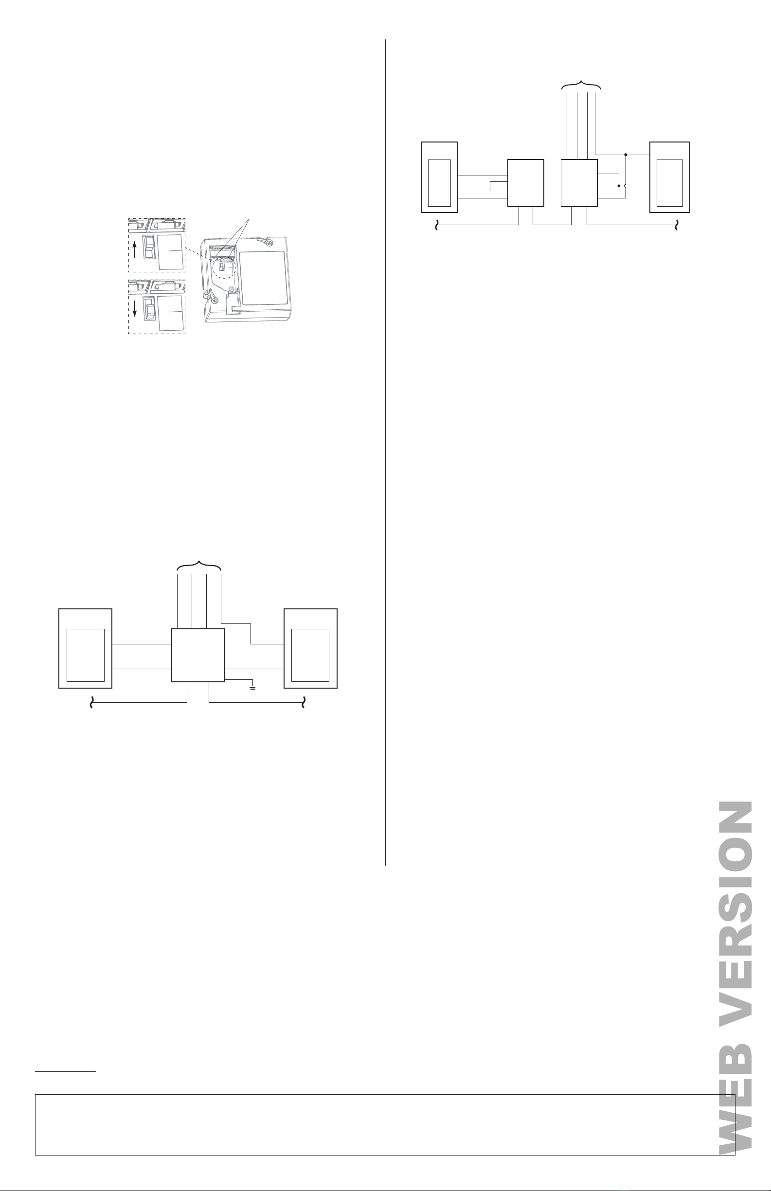
EMERGENCY
Sense Switch
LINE
CAN
EMERGENCY
Sense Switch
LINE
CAN
EMERGENCY
Sense Switch
LINE
CAN
LumaCAN Ports
Emergency Sense Switch
• Can Mode
- On loss of +24VDC LumaCAN power Smart Pack will close RELAY and force 0-10V to MAX
brightness
- On loss of LINE power the Smart Pack will close RELAY and force 0-10V to MAX brightness.
• Line Mode
- On loss of LINE power the Smart Pack will close RELAY and force 0-10V to MAX brightness.
When used in emergency systems:
LumaCan LumaCan
Neutral
Hot
HotWhite
Black
Blue/
White
Neutral
Neutral (white)
0-10V (violet)
Com (gray)
Hot (blue)
Emergency
Lighting
Smart Pack
To Load
Normal
Panel
Emergency
Panel
Green
$
CAN mode (cont'd)
LumaCan LumaCan
Hot
Hot
WH
WH
BLK
BL/WH
Neutral
Neutral
Neutral (white)
LumaCAN
Power
Supply
Normal
Panel
Emergency
Panel
Emergency
Lighting
Smart
Pack
0-10V (violet)
Com (gray)
Hot (blue)
To Emergency
Lighting Load
Green
BLK
$
2. Sense: CAN mode details
WARNING: TO AVOID FIRE, SHOCK, OR DEATH; TURN OFF POWER AT CIRCUIT
BREAKER OR FUSE AND TURN OFF POWER AT THE 24 HOUR NIGHT LIGHT/
EMERGENCY CIRCUIT AND TEST THAT POWER IN BOTH CIRCUITS IS OFF
BEFORE WIRING, SERVICING, OR REMOVING FIXTURE. 7+,6),;785(,6
32:(5('%<7:2&,5&8,767+(5(*8/$532:(5%5$1&+&,5&8,7$1'
7+(+2851,*+7/,*+7(0(5*(1&<&,5&8,7
In this scenario, both the power input wires AND the Load In are connected to the
emergency source. The Smart Pack monitors the LumaCAN cable and upon loss of
power, the relay closes and force the 0-10V control wires to MAX brightness. The
advantage of this scenario is that only emergency power is run to the DRC Smart Pack
so separation of normal and emergency at this location is not required.
In this scenario, the supply input wires are connected to normal power, and the Load
In for the relay is connected to emergency power. Upon loss of normal power, the relay
closes, and the 0-10V lines go to high impedance allowing the load to go to full output
powered from the emergency source. The Emergency Switch must be in the LINE
position. Upon restoration of normal power, DRC Smart Pack will automatically resume
normal operation.
1. Sense: Line mode details
WARNING: TO AVOID FIRE, SHOCK, OR DEATH; TURN OFF POWER AT CIRCUIT
BREAKER OR FUSE AND TURN OFF POWER AT THE 24 HOUR NIGHT LIGHT/
EMERGENCY CIRCUIT AND TEST THAT POWER IN BOTH CIRCUITS IS OFF
BEFORE WIRING, SERVICING, OR REMOVING FIXTURE. 7+,6),;785(,6
32:(5('%<7:2&,5&8,767+(5(*8/$532:(5%5$1&+&,5&8,7$1'
7+(+2851,*+7/,*+7(0(5*(1&<&,5&8,7
3. Emergency self test -
NFPA 101 Life Safety Code and NEC {Article 700.3 (B)} requires regular testing of all emer-
gency equipment. To perform a test of these products, use the EM control breaker to interrupt
normal power to the device, or the device providing power to the LumaCAN network which will
put the Smart Pack into the Emergency behavior. Alternatively, if desired or if your jurisdiction
requires it, you can use a standard toggle switch on the normal power line to trigger the emer-
gency systems test. This test switch must be located local to the load being controlled.
Some jurisdictions may disallow multiple Smart Packs on a test switch or use of breaker in a
panel as a test switch. Clarify with all local authorities.
$
Notes specific to this scenario:
• The Emergency Switch must be in the CAN position.
• CAUTION: The systems designer and installer must verify that any and all power supplies
which could supply power to either LumaCAN cable segment are fed from normal power and
are not connected to a UPS or other power source which could be powered in an emergency
mode condition.
• DRC Smart Pack will go to full output within 1 second.
• Upon restoration of normal power, the DRC Smart Pack will automatically resume normal operation.
• No power provided to LumaCAN network.
WEB VERSION

This manual suits for next models

1

Other Leviton Controllers manuals

Leviton Decora NE515 User manual

Leviton

Leviton Decora NE515 User manual

Leviton HXC4D-1TW Installation instructions

Leviton

Leviton HXC4D-1TW Installation instructions

Leviton PowerSwitch MS4X-302 User manual

Leviton

Leviton PowerSwitch MS4X-302 User manual

Leviton ILLUMATECH INF05-1L User manual

Leviton

Leviton ILLUMATECH INF05-1L User manual

Leviton Intellect ZLDNK User manual

Leviton

Leviton Intellect ZLDNK User manual

Leviton CD250 User manual

Leviton

Leviton CD250 User manual

Leviton GreenMAX DRC User manual

Leviton

Leviton GreenMAX DRC User manual

Leviton vizia rf+ VRCS1 User manual

Leviton

Leviton vizia rf+ VRCS1 User manual

Leviton Decora HCC2D User manual

Leviton

Leviton Decora HCC2D User manual

Leviton Decora Smart DW15P User manual

Leviton

Leviton Decora Smart DW15P User manual

Leviton MLC128R User manual

Leviton

Leviton MLC128R User manual

Leviton DL057-D0Z User manual

Leviton

Leviton DL057-D0Z User manual

Leviton D4200 User manual

Leviton

Leviton D4200 User manual

Leviton Intellect ZL07S-N00 User manual

Leviton

Leviton Intellect ZL07S-N00 User manual

Leviton D3208 User guide

Leviton

Leviton D3208 User guide

Leviton CN221 User manual

Leviton

Leviton CN221 User manual

Leviton Decora Smart User manual

Leviton

Leviton Decora Smart User manual

Leviton MC7008 User manual

Leviton

Leviton MC7008 User manual

Leviton Decora Illumatech IPF05-1L User manual

Leviton

Leviton Decora Illumatech IPF05-1L User manual

Leviton DECORA 661F Series User manual

Leviton

Leviton DECORA 661F Series User manual

Leviton MLC16 User manual

Leviton

Leviton MLC16 User manual

Leviton Decora Illumatech IPF01-1L User manual

Leviton

Leviton Decora Illumatech IPF01-1L User manual

Leviton vizia rf+ User manual

Leviton

Leviton vizia rf+ User manual

Leviton Decora NE505 User manual

Leviton

Leviton Decora NE505 User manual

Popular Controllers manuals by other brands

MKS 350 Series instruction manual

MKS

MKS 350 Series instruction manual

PEMTECH PT900-8FG Operator's manual

PEMTECH

PEMTECH PT900-8FG Operator's manual

Trane Tracer ZN.520 Installation owner diagnostics

Trane

Trane Tracer ZN.520 Installation owner diagnostics

CBS ArcSafe RSA-112 Installation and operation

CBS ArcSafe

CBS ArcSafe RSA-112 Installation and operation

GF EA15 operating instructions

GF

GF EA15 operating instructions

Carel ir33 Universale Replacement instructions

Carel

Carel ir33 Universale Replacement instructions

gefran GFW ADV Installation and Operation Manua

gefran

gefran GFW ADV Installation and Operation Manua

Sony PlayStation Portable Safety guide

Sony

Sony PlayStation Portable Safety guide

Mitsubishi LE-30CTN instruction manual

Mitsubishi

Mitsubishi LE-30CTN instruction manual

ccei Limpido Z2 25 Technical instructions

ccei

ccei Limpido Z2 25 Technical instructions

Epever XTRA-N Series user manual

Epever

Epever XTRA-N Series user manual

Aerotech PRO165SLE Series Hardware manual

Aerotech

Aerotech PRO165SLE Series Hardware manual

Pyrotronix ptx Mini manual

Pyrotronix

Pyrotronix ptx Mini manual

gefran SIEIDrive ADV200 Quick start up guide, Specification and installation

gefran

gefran SIEIDrive ADV200 Quick start up guide, Specification and installation

Mitsubishi Electric PAC-YT34STA user guide

Mitsubishi Electric

Mitsubishi Electric PAC-YT34STA user guide

Satel ACU-270 manual

Satel

Satel ACU-270 manual

Deprag AST6 Operating instruction booklet

Deprag

Deprag AST6 Operating instruction booklet

Emerson PACSystems RX3i IC695CPE330 quick start guide

Emerson

Emerson PACSystems RX3i IC695CPE330 quick start guide

manuals.online logo
manuals.online logoBrands
  • About & Mission
  • Contact us
  • Privacy Policy
  • Terms and Conditions

Copyright 2025 Manuals.Online. All Rights Reserved.