Digital Dream DDCS V3.1 User manual

深圳市众联拓数控科技有限公司
Shenzhen Digital Dream Numerical Technology Co., Ltd.
DDCS V3.1
Software Version No. 2019-04-25-107NOR
All copyrights reserved
Shall not be reproduced without permission.
Standalone Motion Controller
Users Manual V3

Digital Dream Standalone Motion Controller DDCS V3.1 DDCS V3.1 Users ManualPage -1
1 DDCS V3.1 Controller Brief Introduction
1.1 Product Introduction
1.3 Appearance, Structure and Size of Product
1.4 Explanation of Abbreviations
2.6.3 Stepper/Servo Control Output
2.6.4 Power Supply Input
●●●●●●●●●●●●●●●●●●●●●●●●●●●●●●●
●●●●●●●●●●●●●●●●●●●●●●●●●●●●●●●●●●●●●●●●●●●●●●●●●●●●●●
●●●●●●●●●●●●●●●●●●●●●●●●●●●●●●●●●●●●●●●●●●●●●
●●●●●●●●●●●●●●●●●●●●●●●●●●●●●●●●●●●●●
●●●●●●●●●●●●●●●●●●●●●●●●●●●●●●●●●●●●●●●●●●●●●●●●
●●●●●●●●●●●●●●●●●●●●●●●●●●●●●●●●●●●●●●●●●●●●●●●●●●●●●●●●●
●●●●●●●●●●●●●●●●●●●●●●●●●●●●●●●●●●●●●●●●●●●●●●●●●●●●●●●●●●●●●●●●●●●●●
●●●●●●●●●●●●●●●●●●●●●●●●●●●●●●●●●●●●●●●●●●●●●●●●●●●
●●●●●●●●●●●●●●●●●●●●●●●●●●●●●●●●●●●●●●●●●●●●●●●●●●●●
●●●●●●●●●●●●●●●●●●●●●●●●●●●●●●●●●●●●●●●●●●●
●●●●●●●●●●●●●●●●●●●●●●●●●●●●●●●●●●●●●●●●●●●●●●●●●●●●●●●●●●●●●●●●●
●●●●●●●●●●●●●●●●●●●●●●●●●●●●●●●●●●●●●●●●●●●●●●●●●●●●●●●●●●●●●●●●●●
●●●●●●●●●●●●●●●●●●●●●●●●●●●●●●●●●●●●●●●●●●●●●●●●●●●●●●●●●●●●
●●●●●●●●●●●●●●●●●●●●●●●●●●●●●●●●●●●●●●●●●●●●●●●●●●●●●●●
●●●●●●●●●●●●●●●●●●●●●●●
●●●●●●●●●●●●●●●●●●●●●●●●●●●●●●●●●●●●●●●●●●●●●●●●
●●●●●●●●●●●●●●●●●●●●●●●●●●●●●●●●●●●●●●●●●●●●●●●●●●●●●●●●●
●●●●●●●●●●●●●●●●●●●●●●●●●●●●●●●●●●●●●●●●●●●●●●●●
●●●●●●●●●●●●●●●●●●●●●●●●●●●●●●●●●●●●●●●●●●●●●●●●●●●●●●●●●
●●●●●●●●●●●●●●●●●●●●●●●●●●●●●●●●●●●●●●●●●●●●●●●●●●●●●●●●●●●●●●●●●●●
●●●●●●●●●●●●●●●●●●●●●●●●●●●●●●●●●●●●●●●●●●●●●●●●●●●●●●●●
●●●●●●●●●●●●●●●●●●●●●●●●●●●●●●●●●●●●●●●●●●●●●●●●●●●●●●●●●●●●●
●●●●●●●●●●●●●●●●●●●●●●●●●●●●●●●●●●●●●●●●●●●●●●●●●●●●●●●●●●●
●●●●●●●●●●●●●●●●●●●●●●●●●●●●●●●●●●●●●●●●●●●●●●
●●●●●●●●●●●●●●●●●●●●●●●●●●●●●●●●●●●●●●●●●●●●●●●●●●●●●●●●●●●
●●●●●●●●●●●●●●●●●●●●●●●●●●●●●●●●●●●●●●●●●●●●●●●●●●●●●●●●●
●●●●●●●●●●●●●●●●●●●●●●●●●●●●●●●●●●●●●●●●●●●●●●●●●●●●●●●●●●●
●●●●●●●●●●●●●●●●●●●●●●●●●●●●●●●●●●●●●●●●●●●●●●●●●●●●●●●●●●●
●●●●●●●●●●●●●●●●●●●●●●●●●●●●●●●●●●●●●●●●●●●●●●
●●●●●●●●●●●●●●●●●●●●●●●●●●●●●●●●●●●●●●●●●●●●●●●●●●●●●●●●●●●●●
3
3
4
5
7
7
8
8
8
9
9
10
12
15
16
18
19
20
20
20
24
25
26
28
28
31
31
33
34
35
Contents
1.2 DDCS V3.1 Brief technical feature
2.5 MPG Port
2.3 START/PAUSE/ESTOP Switch Wiring
2.4 USB Wiring
3.1.3 Parameter Page
3.2 Definition of Keys
3.3 Operation of common functions
3.3.1 File Management
3.3.2 Running a G code file
3.3.2.2 Breakpoint operation
3.3.2.3 Start a G code file from a specific line
3.3.2.4 Pause in operation
2.6 Main Port Wiring
2.6.1 Spindle control output
2.6.2 Limit, Home and Probe Inputs,and the Power for the Input
3 Software and Operation
3.1 Interface description
3.1.1 Main page
3.1.2 File Management Page
2 Wiring
2.1 Power supply explanation
2.2 Product Wiring Overview
1.5 Notes and Warnings
3.3.2.1 Start running G code

Digital Dream Standalone Motion Controller DDCS V3.1 DDCS V3.1 Users ManualPage -2
●●●●●●●●●●●●●●●●●●●●●●●●●●●●●●●●●●●●●●●●●●●●●
●●●●●●●●●●●●●●●●●●●●●●●●●●●●●●●●●●●●●●●●●●●●●●●●●●●●●●●●
●●●●●●●●●●●●●●●●●●●●●●●●●●●●●●●●●●●●●●●●●●●
●●●●●●●●●●●●●●●●●●●●●●●●●●●●●●●●●●●●●●●●●●●●●●●●●●●●●●●
●●●●●●●●●●●●●●●●●●●●●●●●●●●●●●●●●●●●●●●●●●●●●
●●●●●●●●●●●●●●●●●●●●●●●●●●●●●●●●●●●●●●●●●●●●●●●●●●●●●●●●●●●●●●
●●●●●●●●●●●●●●●●●●●●●●●●●●●●●●●●●●●●●●●●●●●●●●●●●●●●●●●●●●●●●●
●●●●●●●●●●●●●●●●●●●●●●●●●●●●●●●●●●●●●●●●●●●●●●●●●●●●●●●●●●●●●●
●●●●●●●●●●●●●●●●●●●●●●●●●●●●●●●●●●●●●●●●●●●●●●●●●●●●●●●●●●●
●●●●●●●●●●●●●●●●●●●●●●●●●●●●●●●●●●●●●●●●●●●●●●●●●●●●●●●●●●●
●●●●●●●●●●●●●●●●●●●●●●●●●●●●●●●●●●●●●●●●●●●●●●●●●●●●●●
●●●●●●●●●●●●●●●●●●●●●●●●●●●●●●●●●●●●●●●●●●●●●●●●●●●●●●●●●●●●●●●
●●●●●●●●●●●●●●●●●●●●●●●●●●●●●●●●●●●●●●●●●●●●●●●●●●●●●●●●●●●●●●●●●●●●
●●●●●●●●●●●●●●●●●●●●●●●●●●●●●●●●●●●●●●●●●●●●●●●●●●●●●●●●●●●●●●●●●●●●●●●●
●●●●●●●●●●●●●●●●●●●●●●●●●●●●●●●●●●●●●●●●●●●●●●●●●●●●●●●●●●●●●●●●●●●●●●●
●●●●●●●●●●●●●●●●●●●●●●●●●●●●●●●●●●●●●●●●●●●●●●●●●●●●●●●●●●●●●●●●●●●●●●●
●●●●●●●●●●●●●●●●●●●●●●●●●●●●●●●●●●●●●●●●●●●●●●●●●●●●●●●●●●●●
●●●●●●●●●●●●●●●●●●●●●●●●●●●●●●●●●●●●●●●●●●●●●●●●
●●●●●●●●●●●●●●●●●●●●●●●●●●●●●●●●●●●●●●●●●●●●●●●●●●●
●●●●●●●●●●●●●●●●●●●●●●●●●●●●●●●●●●●●●●●●
●●●●●●●●●●●●●●●●●●●●●●●●●●●●●●●●●●●●●●●●●●●●●●●●●
●●●●●●●●●●●●●●●●●●●●●●●●●●●●●●●●●●●●●●●●●●●●●●●●●●●●●●
●●●●●●●●●●●●●●●●●●●●●●●●●●●●●●●●●●●●●●●●●●●●●●●●●●●
35
36
36
●●●●●●●●●●●●●●●●●●●●●●●●●●●●●●●●●●●●●●●●●●●●●●●●●●●●●●●●●●●● 35
●●●●●●●●●●●●●●●●●●●●●●●●●●●●●●●●●●●●●●●●●●●●●●●●●●●●●●●●●●●● 35
37
37
38
38
39
40
42
43
45
45
47
49
51
●●●●●●●●●●●●●●●●●●●●●●●●●●●●●●●●●●●●●●●●●●●●●●●●●●●●●●●●●● 59
59
62
64
64
73
75
81
3.3.2.5 ESTOP in operation
3.3.2.6 Start/Stop spindle
3.3.3 Manually position the machine
3.3.3.1 Manual step of the X axis
3.3.3.2 Manual continuous operation of the X axis
3.3.3.3 Use MPG to operate X axis
3.3.4 Main Page Parameter adjustments
3.3.4.3 Adjust SJR Value
3.3.4.2 Adjust SRO Value
3.3.4.1 Adjust FRO Value
3.3.4.4 F Value modification
3.3.4.5 S Value modification
3.3.4.6 Select G coordinate system
3.3.5.1 Go To Zero
3.3.5 The 2nd Mode
3.3.5.2 Zero
3.3.5.4 Probe
3.5 Software Update
3.3.5.5 Trial Cutting Funciton
3.3.5.3 Home
3.6 Keyboard Operation Methods
4.2 Save the Parameters Setting
5 G Code and M Code
6 Questions and Answer
4.1 The detailed definition of parameters
4 Parameter Instruction

Digital Dream Standalone Motion Controller DDCS V3.1 DDCS V3.1 Users ManualPage -3
1 DDCS V3.1 Controller Brief Introduction
1.1 Product Introduction
Thank you for your interest in our standalone motion controller and for taking the time to
read this manual.
Digital Dream is a numerical control company specializing in the research, development
and production of various CNC (Computer Numerical Control) systems since 2008. Digital Dream
aims to combine high quality and high reliability with affordability.
The DDCS is a 3~4 axes motion controller for stepper and servo systems. DDCS V3.1 is updat-
ed from DDCS V2.1 on software and hardware.We are very proud of this product, it combines
great power with a tiny footprint and is easy to use. After a very short time you will be familiar
with the functions and this manual will help you. The highest output pulse per axis is 500KHz.
This provides high control precision for stepper motors and servo motors.
The DDCS numerical control system adopts the ARM+FPGA design framework. ARM controls
the human-computer interface and code analysis and the FPGA provides the underlying algo-
rithms and creates the control pulse. This guarantees reliable control and easy operation. The
internal operating system is Linux based.
The panel layout structure of the DDCS V3.1 is very rational to save space. All operations are
controlled by only 17 keys and a comprehensive G code set is supported.
The DDCS can be used for many styles and types of CNC machines. Lathes, Routers, Pick&-
Place and Mills are just a few examples. The DDCS operates as a Stand Alone system without the
need of a computer. This guarantees high precision, accuracy and reliability. The interface, even
though very comprehensive, can be learned in a very short time.
The copyright of this manual belongs to Shenzhen Digital Dream Numerical Technology Co.,
Ltd. (herein after referred as Digital Dream Company). This manual and any image, table, data or
other information contained in this manual may not be reproduced, transferred, or translated
without any prior written permission of Digital Dream Company.
The information contained in this manual is constantly being updated. You can login to the
official website of Digital Dream Company www.ddcnc.com to download the latest PDF edition
for free.

Digital Dream Standalone Motion Controller DDCS V3.1 DDCS V3.1 Users ManualPage -4
1.2 DDCS V3.1 Brief technical feature:
1) 16 photoelectric isolated digital inputs,3 photoelectric isolated digital outputs;
2) 3.1 Version enhanced Algorithm,support soft interpolation,fixed arc interpolation bug of
the old version;
3) Analog spindle control 0-10V spindle control (can be modified as PWM output);
4) 3-4 axes motor Control.Differential Pulse and direction output signal,Max.500Khz per
axis;
5) ARM9 main control chip,FPGA core algorithm chip;
6) 5 inches TFT screen, resolution ratio: 480x272,17 operation keys;
7) The Power Supply for the controller is 24VDC, minimum Current is 0.5A;
8) The Power Supply for IO Port is 24VDC,minimum current is 0.5A;By the IO power
supply,system already supply the power for IO ports.So no need the external power supply for
IO port anymore;
9) USB flash disk support for G code file input,no size limited of the G-code file ;
10) Support standard MPG;
11) Jog function for each axis (continuous, step, defined distance);Customer can define the
distance;
12) Support the operation of quickly specify the running position;
13) Support for “Power Cut” recovery. Data is automatically saved;
14) Backlash compensation, Tool compensation
1) Control System Unit is compatible with Metric Units and Imperial Units;
2) MPG and extended Keyboard can also control and edit the controller system;
3) Add new function of “Try cutting”(handwheel guiding) and “Single-stage processing
mode” ;
4) 3 kinds Probing Modes:Fixed Position of tool sensor,Floating Position of the tool
sensor,Rectangular block Sensor;
5)Enhanced the software,added a lot of parameters,Optimal Design and algorithm,makes
the new version more strong functions and steady;
6) The Option Language of the system is Chinese/English/Russian.
7) Version 3.1 cited the new circuit design and metal box,which can avoid the noise a lot.
DDCS V3.1 New features compared to previous version:

Page -5Digital Dream Standalone Motion Controller DDCS V3.1 DDCS V3.1 Users Manual
The DDCS V3.1 is a small box that can fit in a window of a small control box or control cabi-
net. Four locking hooks fix this controller from the frame. The dimension you find in Figure 1-1
and Figure 1-2.
The front panel is 191mm*128mm*5mm;
The main body is 191mm*128mm*37mm;
To mount the unit in an equipment cabinet, cut the hole182.5mm*59mm
1.3 Appearance, Structure and Size of Product
5 mm
128 mm
191 mm
182.5 mm
59 mm
37 mm
175 mm
110 mm
Figure 1-1 DDCS V3.1 Front and back view and dimensions
Figure 1-2 DDCS V3.1 Rear view and dimensions

Page -6Digital Dream Standalone Motion Controller DDCS V3.1 DDCS V3.1 Users Manual
5'' Screen
17 Buttons
The front panel consists of 17 user keys and the 5’’ (480*272) LCD.
At the back side of the controller,there are USB Disk interface,MPG Port,Main Port and exter-
nal Start/Pause/Estop interface.
For convenient connections we supply a 3 layer wiring terminalfor main port.
We also supply a DB-15 Male plug for MPG connection.
The 8 screws are to fix the wiring ternimal and controller.
The USB Stick is for the transfer of the G-code file.
Figure1-3 Front panel
Figure 1-4 Back side of the controller and the accessories

Digital Dream Standalone Motion Controller DDCS V3.1 DDCS V3.1 Users ManualPage -7
When operating the DDCS, the users will come across some English abbreviations. Here a
list with explanations
FRO: Feed Rate Override
SRO: Spindle Rate Override
SJR: Jog Speed Setting
F: Feed rate, unit is mm/min
S: Spindle Speed, unit rev/min.
X: The coordinate code of the X axis.
Y: The coordinate code of the Y axis.
Z: The coordinate code of the Z axis.
A: The coordinate code of the A axis
BUSY: The system is busy. You still can adjust FRO and SRO
READY: READY mode, any operation can be done
RESET: Reset mode, controller is in “OFF” mode, no operation can be performed
CONT: Continuous mode, each axis can be manually jogged with the arrow keys
Step :Manual Step Mode,each axis can be jogged in defined steps
MPG: MPG mode. Operate the machine with the MPG (Manual Pulse Generator)
AUTO: Run G code. Auto is showing when file is processing
1.4 Explanation of Abbreviations
Keep away from exposure to moisture or water. This product contains sophisticated
electronics and must not get wet.
Wiring warning: the IO input terminal of this controller supports equipment with source
power (such as Inductive Proximity Switch ). When using this kind of equipment, pay attention
to the polarity. Avoid the +terminal to be connect with GND. This controllers has analog output
for spindle control (0-10V). Please avoid this terminal to ever connect with GND as damage to
the controller may occur.
Operation warning. Please observe all security measures when operating the
machine. The ESTOP must be connected and properly labelled. In case of a problem, press the
E-stop at once to avoid damage to humans, animals and the equipment.
High voltage danger. The DDCS is connected to 24V DC. Obey and follow the electrici-
ty safety rules of your country when connecting this equipment.
1.5 Notes and Warnings

Digital Dream Standalone Motion Controller DDCS V3.1 DDCS V3.1 Users ManualPage -8
In general, the power supply of industrial control’s equipment products are complex. They
have many different ground levels. The internal power structure of this product is as follows:
See Figure 2-1. The Controller need two power supplies,Main power is for system,IO Power
is for IO ports.The Main Power input and USB stick and Stepper/Servo Control module share the
same ground.IO Power,MPG Port,Spindle PWM,12 Inputs and 3 Outputs share same ground,
between them which is optical isolation. As for the spindle port, take the output ground for
references and the 0-10V adjustable voltages to adjust the spindle speed (refer to spindle VFD
manual). The M3/M8/M10 digital output ports pull to ground.
Figure 2-1 Power supply System structure
2 Wiring
2.1 Power supply explanation
2.2 Product Wiring Overview
Figure 2-2 Wiring and Ports
MPG Ports
Start/Pause/Estop Switch
USB Port
Stepper or Servo Ports
Input Ports
Spindle&Output Ports
Power Supply

Page -9Digital Dream Standalone Motion Controller DDCS V3.1 DDCS V3.1 Users Manual
As Figure 2-3 shows, the power interface,there is a screw termimal for connection. The
marks are the “START”/”PAUSE”/”ESTOP” and “COM” for external switches. And Figure 2-4 is
the circuit drawing for the connection.The “Start” and “Pause” can be defined as other func-
tions.Detailed information please refers to #446 and #447 in Param Page.
2.3 START/PAUSE/ESTOP Switch Wiring
This USB port is the standard USB A-type. A 50cm USB extension cord with installation plug
is supplied with the controller. See the diagram Figure 2-5 for reference.
2.4 USB Wiring
Figure 2-4 Circuit drawing of START/PAUSE/ESTOP/COM
Figure 2-5 USB interface
Figure 2-3 START/PAUSE/ESTOP/COM interface
As the Figure shows, the wiring section of the controller has Input Ports,Spindle&Output
Ports,stepper/Servo control step and direction output,MPG Port, USB Port and Power supply
Port.

Page -10Digital Dream Standalone Motion Controller DDCS V3.1 DDCS V3.1 Users Manual
The MPG port is shown in Figure 2-6. It is the DB15 Female terminals next to the USB port.
The users need to weld the MPG cables into the DB15 Male terminal,and plug-in to the MPG port
of the controller MPG port.
NOTE:Only when the IO port’s power supply is wired correctly, will the MPG work correctly.
The MPG port has 15 pins, see Table 2-1 for reference. See Table 2-2 and table 2-3 for the wiring.
2.5 MPG Port
Table 2-1 DDCS’s MPG Port
Figure 2-6 MPG port and accessory connector for it
Pin No. Pin Mark Definition Notes
ESTOP of MPG Connect with GND, indicate ESTOP is in effect.Open indicates Estop is invalid.
Select switch 1 X Connect with GND, indicates selecting1 X, open indicates no pulse
Select switch 10 X Connect with GND, indicates selecting10 X, open indicates no pulse
Select switch 100 X Connect with GND, indicates selecting100 X, open indicates no pulse
MPG Power supply Ground MPG power supply ground
MPG B phase negative MPG B phase differential input negative terminal
MPG A phase negative MPG A phase differential input negative terminal
MPG Power Supply 5V Positive Exclusive Power supply Positive of MPG, which can restore the fuse
connection with a 200MA of the system power supply.
Select switch of X axis Connect with GND,indicates selecting X axis, open indicates no selecting
Select switch of Y axis Connect with GND, indicates selecting Y axis, open indicates no selecting
Select switch of Z axis Connect with GND,indicates selecting Z axis, open indicates no selecting
Select switch of A axis Connect with GND, indicates selecting A axis, open indicates no selecting
MPG B phase positive MPG B differential input positive terminal
MPG A phase positive MPG A phase differential input positive terminal
Switch Signal common terminal the switch signal common trenimal, which can restore the fuse
connection with a 200MA of the system power supply.
ESTOP
X1
X10
X100
GND
WHB-
WHA-
+5V-W
X-IN
Y-IN
Z-IN
A-IN
WHB+
WHA+
COM-
15
7
14
6
9
10
11
1
4
12
5
13
2
3
8

Page -11Digital Dream Standalone Motion Controller DDCS V3.1 DDCS V3.1 Users Manual
Table 2-2 DDCS Wiring with standard MPG
Table 2-3 DDCS Wiring with Single-terminal MPG
Note: It you want to use the single-terminal MPG (there is no A-B-MPG), please refer to table 2-3
for reference. As for the unlisted MPG, please take the differential MPG wiring mode.
DDCS Wiring Pin
Blue
X1 Grey
X10 Black/Grey
X100 Orange
X Yellow
Y Black/Yellow
Z
X1 Ratio
X100 Ratio
X Axis
Z Axis Brown
A Black/Brown
A+ Green
A- Purple
B+
B-
A Phase -
B Phase -
A Phase +
B Phase + White
Purple/Black
COMEnable Switch Black/Orange,Blue/Yellow
Black,Whilte/Black
Red, Green/BlackVcc(+5V)
ESTOP ESTOP
X10 Ratio
Y Axis
A Axis
ESTOP
X1
X10
X100
GND GNDPower Supply -
Power Supply +
WHB-
WHA-
+5V-W
X-IN
Y-IN
Z-IN
A-IN
WHB+
WHA+
WHB-
WHA-
WHB+
WHA+
COM-
MPG Function MPG Pin Mark MPG Output Cable Color
A+ Green
0V Black
B+ White
0V Black
DDCS Wiring Pin Mark MPG Pin Mark and Color

Page -12Digital Dream Standalone Motion Controller DDCS V3.1 DDCS V3.1 Users Manual
Figure 2-7 shows the main port position:
We supply a wiring terminal to fit the 37 pin female connector of the main port. This simpli-
fies the wiring. Please note in Figure 2.8, at the 4 corners, there are screws to lock the terminal
to the controller.
2.6 Main Port Wiring
Figure 2-7 Main Port
Figure 2-8 Main Port with wiring terminal

Page -13
Digital Dream Standalone Motion Controller DDCS V3.1 DDCS V3.1 Users Manual
There are 3 rows of connectors on the terminal block. Please see Pic 2-9 which shows the
shows the pin allocation to each row. It supports the following interfaces:
1) Stepper/Servo Output Ports;
2) The Spindle Control Output Ports;
3) The E-stop,Limit,Home and Probe and other Inputs ports;
4) 24V DC Power Supply ports for the Controller;
5) 24V DC Power Supply ports for the I/O Unit.
For the connector to pin mapping please refer to Table 2-4:
Figure 2-9 3-Layers wiring terminal
First Layer of the Terminal
Pin 18:AD-
Pin 2:VSO
Pin 36:AD+
Pin 1:COM-
Pin 1:COM-
Pin 19:24V
Second Layer of the Terminal
Third Layer of the Terminal
Table 2-4 Main Port Pin No. and Mark
PIN 1 PIN 1
COM- COM-
PIN 23 PIN 3PIN 20
XL++ M8COM+ AL--
ZHOME
ZL++
XHOME
PROBE
PIN 28 PIN 27 PIN 26 PIN 24 PIN 4
PIN 18 PIN 17 PIN 16 PIN 15 PIN 14 PIN 13 PIN 12 PIN 11
AD- AP- ZD- ZP- YD- YP- XD- XP-
First Layer of the Terminal
PIN 25 PIN 2
YL-- VSO
GND24V COM+
PIN 37PIN 19 PIN 20
Third Layer of the Terminal
PIN 6
YL++
AL++ ZL--
YHOME
M3 COM-
PIN 9 PIN 8 PIN 7 PIN 21 PIN 1PIN 36 PIN 35 PIN 34 PIN 33 PIN 32 PIN 31 PIN 30 PIN 29 PIN 5 PIN 22PIN 1
AD+ AP+ ZD+ ZP+ YD+ YP+ XD+ XP+ XL-- M10COM-
Second Layer of the Terminal
AHOME
PIN 10
The Pin No. is DB37 interface Pin No.

Page -14
Digital Dream Standalone Motion Controller DDCS V3.1 DDCS V3.1 Users Manual
Table 2-5 Main Port Pin No. and definition
AL--
ZHOME
ZL++
XHOME
PROBE
PIN 28
PIN 27
PIN 26
PIN 24
PIN 4
Limited Signal Input at A-- direction
Limited Signal Input at Z++ direction
Probe Signal Input
Home Signal Input of X Axis
Home Signal Input of Z Axis
PIN 18
PIN 17
PIN 16
PIN 15
PIN 14
PIN 13
PIN 12
PIN 11
PIN 23
PIN 3
PIN 20
AD-
AP-
ZD-
ZP-
YD-
YP-
XD-
XP-
XL++
M8
COM+
Direction Signal Negative Output of A Axis (5V)
Pulse Signal Negative Output of A Axis (5V)
Direction Signal Negative Output of Z Axis (5V)
Pulse Signal Negative Output of Z Axis (5V)
Direction Signal Negative Output of Y Axis (5V)
Pulse Signal Negative Output of Y Axis (5V)
Direction Signal Negative Output of X Axis (5V)
Pulse Signal Negative Output of X Axis (5V)
Limited Signal Input at X++ direction
Start Cooling Signal Output for Spindle
First Layer of the Terminal
Pin No. Pin Mark Definition
PIN 25
PIN 2
YL--
VSO Speed output(0-10V) VSO Signal Output
Limited Signal Input at Y-- direction
All between “COM+”s are conducting.All between “COM-”s are conducting.
Between COM+ and COM- there is 24VDC power.COM+ is Positive side.
AHOME
AL++
YHOME
M3
COM-
COM-
PIN 10
PIN 9
PIN 7
PIN 21
PIN 1
Limited Signal Input at A++ direction
Home Signal Input of A Axis
Home Signal Input of Y Axis
Start Spindle Signal Output
PIN 36
PIN 35
PIN 34
PIN 33
PIN 32
PIN 31
PIN 30
PIN 29
PIN 5
PIN 22
PIN 1
AD+
AP+
ZD+
ZP+
YD+
YP+
XD+
XP+
XL--
M10
Direction Signal Positive Output of A Axis (5V)
Pulse Signal Positive Output of A Axis (5V)
Direction Signal Positive Output of Z Axis (5V)
Pulse Signal Positive Output of Z Axis (5V)
Direction Signal Positive Output of Y Axis (5V)
Pulse Signal Positive Output of Y Axis (5V)
Direction Signal Positive Output of X Axis (5V)
Pulse Signal Positive Output of X Axis (5V)
Limited Signal Input at X-- direction
Start Lubrication Signal Output for Spindle
All between “COM+”s are conducting.All between “COM-”s are conducting.
Between COM+ and COM- there is 24VDC power.COM- is Negative side.
All between “COM+”s are conducting.All between “COM-”s are conducting.
Between COM+ and COM- there is 24VDC power.COM- is Negative side.
GND
24V Positive Side of Power Supply for Controller system
Negative side of Power Supply for controller system
Positive Side of Power Supply for IO Port
Negative side of Power Supply for IO Port
Third Layer of the Terminal
Pin No. Pin Mark Definition
COM-
COM-
COM+
PIN 37
PIN 19
PIN 1
PIN 1
PIN 20
All between “COM+”s are conducting.All between “COM-”s are conducting.
Between COM+ and COM- there is 24VDC power.COM- is Negative side.
Second Layer of the Terminal
Pin No. Pin Mark Definition
ZL--PIN 8
Limited Signal Input at Z-- direction
PIN 6 YL++ Limited Signal Input at Y++ direction

Page -15
Digital Dream Standalone Motion Controller DDCS V3.1 DDCS V3.1 Users Manual
PIN3(M8),PIN22(M10),PIN2(VSO) and PIN21(M3) is for spindle control output.The spindle
control output terminal offers connections for Start and Stop of the Spindle (M3/M5), Start/Stop
of Cooling (M8/M9) and Start/Stop of Lubrication (M10/M11). These three output terminals are
signals open to ground. The highest electric current can be absorbed is 50mA. The speed
controlling output terminal can output 0-10V. It can adjust the speed of the spindle motor by
sending the voltage between 0 and 10V to the VFD according the the Spindle Speed Setting.
Controlling the speed of a spindle with a VFD (variable frequency drive) only needs the
Start/Stop signal and the 0-10V signal to control the frequency.
The following table 2-6 shows the wiring with Sunfar VFD:
PIN3(M8),PIN22(M10) and PIN21(M3) is also can be used for OUTPUT ports.For example,it
can be used for a Relay output port.For example the Figure 2-10 shows the wiring methods:
2.6.1 Spindle control output
Figure 2-10 Wiring Methods with Relay
DDCS V3.1 Wiring pin SUNFAR E300
AI
FWD
CM
Speed output(0-10V)PIN2(VSO)
Start and stop of spindle PIN21(M3)
Output ground
Table 2-6 DDCS and VFD wiring
PIN20:COM+
PIN22:M10

Page -16
Digital Dream Standalone Motion Controller DDCS V3.1 DDCS V3.1 Users Manual
Figure 2-12 The Limit wiring at X++ direction with mechanical limited switch
X++ Limit
COM-
2.6.2 Limit, Home and Probe Inputs,and the Power for the Input
PIN6(YL++),PIN23(XL++),PIN25(YL--),PIN5(XL--),PIN28(AL--),PIN9(AL++),PIN8(ZL--),PIN26(ZL++)
are the Limit ports.
PIN10(AHOME),PIN27(ZHOME),PIN7(YHOME),PIN24(XHOME) are the Home Ports.
PIN4(PROBE) is the Probe Port.
The following wiring Figures and circuit Figures will show the connection of the Limit,Home
and Probe Wiring.
Figure 2-11 LIMIT,HOME and PROBE input signal circuit

Page -17Digital Dream Standalone Motion Controller DDCS V3.1 DDCS V3.1 Users Manual
Figure 2-14 The circuit of
3-line Inductive proximity switch
Figure 2-13 The Limit wiring at X++ direction with
3-line proximity switch
Figure 2-15 The Probe Wiring
COM- PROBE
X++ Limit
COM+
COM-

Page -18Digital Dream Standalone Motion Controller DDCS V3.1 DDCS V3.1 Users Manual
2.6.3 Stepper/Servo Control Output
The stepper/servo control output,we cite differential Pulse and Direction output method,Max.
500Khz per axis.DDCS V3.1 there is 3 or 4 axis for option
PIN 18 (AD-),PIN 36 (AD+),PIN 17 (AP-),PIN 35 (AP+) is A Axis Control Output Pins;
AD- means the Direction signal negative output for A axis,AP+ means the Direction signal posi-
tive output for A axis,AP- means the Pulse signal negative output,AP+ means the Pluse Signal posi-
tive output.
The Pulse and Direction signal output voltage is ±5V.
PIN 18(AD-),PIN 36 (AD+),PIN 17 (AP-),PIN 35 (AP+) is A Axis Control Output Pins;
PIN 16 (ZD-),PIN 34 (ZD+),PIN 15 (ZP-),PIN 33 (ZP+) is Z Axis Control Output Pins;
PIN 14 (YD-),PIN 32 (YD+),PIN 13 (YP-),PIN 31 (YP+) is Y Axis Control Output Pins;
PIN 12 (XD-),PIN 30 (XD+),PIN 11 (XP-),PIN 29 (XP+) is X Axis Control Output Pins.
The following Figure 2-16 is the example of stepper driver wiring as A axis.
AD-
AP-
AD+
AP+
Figure 2-16 The Stepper driver wiring as A Axis

Page -19
Digital Dream Standalone Motion Controller DDCS V3.1 DDCS V3.1 Users Manual
2.6.4 Power Supply Input
Figure 2-17 Power Supply for Controller System and IO port
DDCS V3.1 needs two power supplies,Main power is for system,IO Port is for Input and
Output ports. Both power supply is 24VDC,current is not less then 1A.In the Main port inter-
face,the marked 24V and GND is the main power input ports;the COM+ and COM- is the IO power
input ports.Please keep in mind,only when the two power supplies are connected correctly the
controller can be work properly.
Becasue of the IO power,the controller system can supply power to all the IO ports,the IO
ports is no need of the external power any more,for example,the relay.
In order to avoid electrical noise it is highly recommended to use two separate 24V power
supplies.
Note also that the stepper motors/servo motors should be powered from a separate higher
capacity power supply as these really are a source of electrical noise.
Main Power for System
IO Power for Input and Output
Table of contents
Other Digital Dream Controllers manuals
Digital Dream
Digital Dream UC300 User manual
Digital Dream
Digital Dream EC500 User manual
Digital Dream
Digital Dream DDCS-Expert User manual
Digital Dream
Digital Dream DM500 User manual
Digital Dream
Digital Dream NCH02 User manual
Digital Dream
Digital Dream DM500T3 User manual
Digital Dream
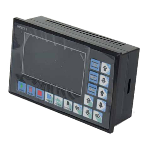
Digital Dream DDCS V2.1 User manual
