00-03
D F E P
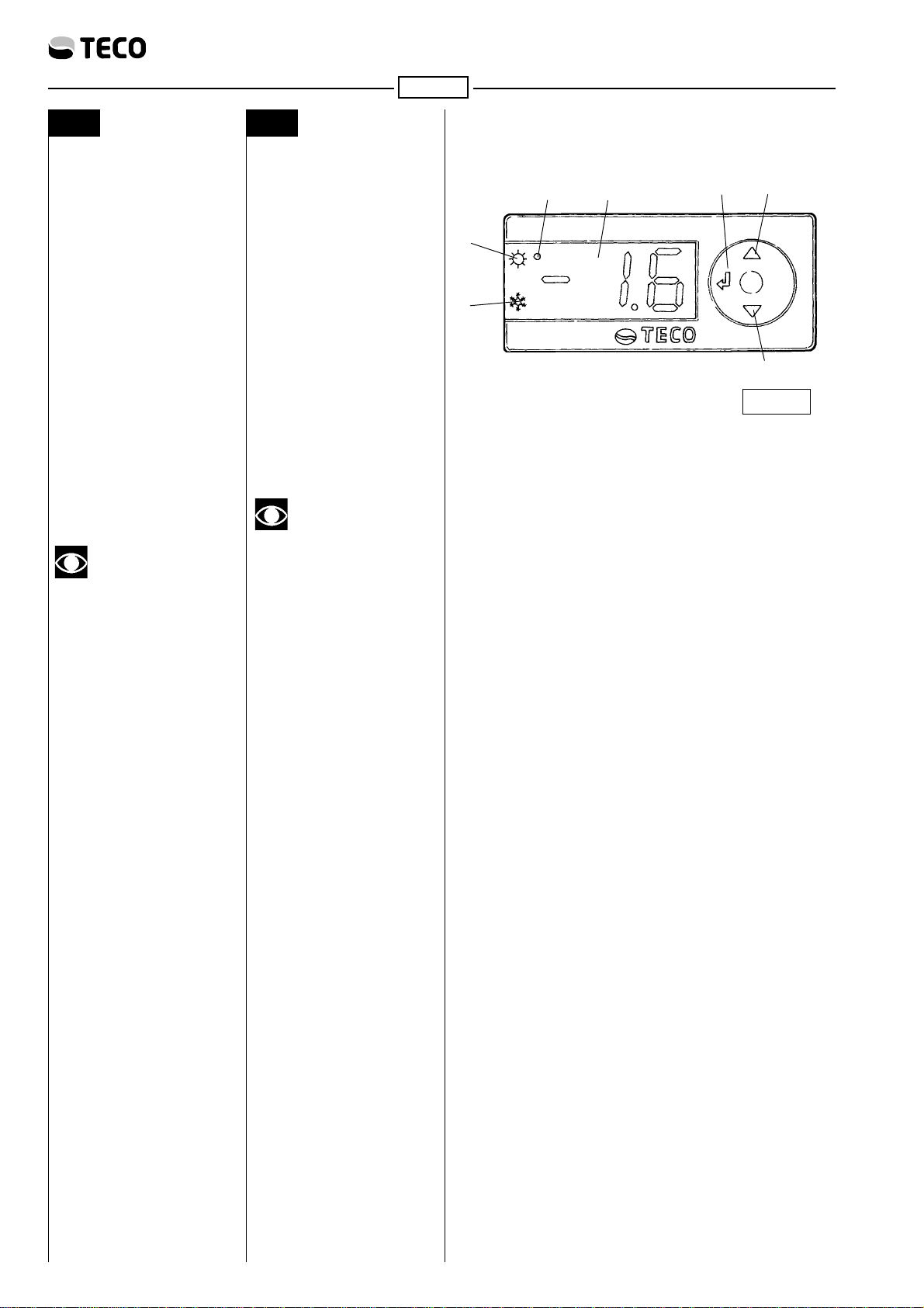
A BEDIENUNGSTAFEL
UND KONTROLLFELD
Beschreibung
18: Schalter zur
Programmierung der
Temperatur
2DISPLAY: Sichtgerät der
Temperatur
3s : Schalter zur
Erhöhung der Temperatur
4t : Schalter zur
Erniedrigung der
Temperatur
5l : Kontrollämpchen
zur Anzeige Kühler in
Funktion
6l : Kontrollämpchen
zur Anzeige Heizer
eingeschaltet (CA)
7l : Kontrollämpchen
zur Anzeige
Programmierung möglich
WICHTIG
Sind die ausgewählten
Temperaturen erreicht
worden so schalten sich die
Kontrollämpchen Bezugspkt.
“5” und Bezugspkt. “6” aus.
B PROGRAMMIERUNG
DER TEMPERATUR
Taste 1 gedrückt halten, bis die
Anzeige SET erscheint. Dann
erneut die Taste 1 drücken. Auf
dem Display erscheint die
Kontrolllampe 7 für die Anzeige
derProgrammierfunktionundes
wird die zuvor eingestellte
Temperatur angezeigt.
Die Tasten 3 (Erhöhen) oder 4
(Vermindern) drücken, um die
gewünschte Temperatur
einzustellen.
Dann zum Bestätigen die Taste
1gedrückthalten,bisdieAnzeige
SET erlischt. Anschließend wird
die vom Temperaturfühler
gemessene Temperatur
angezeigt.
Kontrolllampe5zeigtan,dasssich
derKühlerinBetriebbefindet.
Kontrolllampe6zeigtan,dasssich
dasHeizgerätinBetriebbefindet.
DieDatenderkleinen
elektronischenZentrale,dievom
Herstellerbereitsvorher
eingegebensind,sindwiefolgt:
•Differential 1° C über der vom
Verbrauchereingegebenen
Temperatur
A PANEL DE CONTROL
Y MANDO
Descripción
1 8:Botónpara
programar la temperatura
2 DISPLAY: Visualizador de
temperatura
3s : Botón para
aumentar la temperatura
4t : Botón para
disminuir la temperatura
5 : Luz de aviso
que indica que el
refrigerador está
funcionando
6l : Luz de aviso
que indica que la
resistencia está
funcionando
7l : Luz de aviso
que indica que se puede
programar
IMPORTANTE
Cuando se alcanzan las
temperaturas elegidas los luz
de aviso Ref. “5” y Ref. “6”
se apagan.
B PROGRAMACIÓN DE
LA TEMPERATURA
Mantener presionada la tecla 1
hasta obtener la aparición del
mensaje SET, y a continuación
presionarnuevamentelatecla1;
enelmonitorapareceráeltestigo
luminoso 7 indicador de la
modalidad de programación,
ademásdelvalordetemperatura
precedentemente predispuesto.
Presionar el pulsador 3
(incremento)o4(reducción)para
programar la temperatura
preferida; a continuación
confirmar dicho valor
manteniendopresionadalatecla
1 hasta obtener nuevamente la
aparición del mensaje SET y la
sucesiva visualización de la
temperatura leída por la sonda.
El testigo luminoso 5 señala la
eventual puesta en marcha del
refrigerador.
El testigo luminoso 6 señala la
eventual puesta en marcha del
calentador.
Los datos de la centralita
electrónica predefinidos por el
fabricante son:
•Diferencial 1° C sobre o bajo
latemperaturadefinidaporel
usuario
A PAINEL DE
CONTROLE E
COMANDOS
Descrição
18: Tecla para
programação da
temperatura
2 DISPLAY: Visualização da
temperatura
3s : Tecla para
aumento temperatura
4t : Tecla para
diminuição temperatura
5l : Indicador
luminoso sinalização
refrigerador a funcionar
6l : Indicador
luminoso sinalização
resistência a funcionar
7l : Indicador
luminoso sinalização
possibilidade de
programação
IMPORTANTE
Ao chegar às temperaturas
seleccionadas, os indicador
luminosos Ref. “5” e Ref.
“6” apagam-se.
4.1 PROGRAMAÇÃO DA
TEMPERATURA
Mantercarregadaatecla1atéo
aparecimento da palavra SET,
depois carregar novamente a
tecla 1; no display aparecerá o
indicador luminoso 7 de
sinalização da modalidade de
programação e o valor da
temperatura anteriormente
programada.
Carregarosbotões3(aumento)
ou 4 (diminuição) para
programar a temperatura
desejada, depois confirmar o
valor mantendo carregada a
tecla 1 até o aparecimento da
palavra SET e a sucessiva
visualizaçãodatemperaturalida
pela sonda.
O indicador luminoso 5 indica a
eventual entrada em função do
refrigerador.
O indicador luminoso 6 indica a
eventual entrada em função do
aquecedor.
Os dados da central eletrónica
previamente programados
pelo fabricante são:
•Diferencial 1° C acima ou
abaixo da temperatura
programadapeloutilizador
A PANNEAU DE
CONTROLE ET DE
COMMANDE
Description
18:Touchede
programmation de la
température
2DISPLAY: Ecran de
température
3s : Touche
d’augmentation de la
température
4t :Touche de
diminution de la
température
5l :Voyant lumineux
de signalement de
réfrigérateur en fonction
6l :Voyant lumineux
de signalement de
résistance allumée (CA)
7l :Voyant lumineux
de possibilité de
programmation
IMPORTANT
Lorsque la température
choisie est atteinte les
voyant lumineux de
signalement Réf. “5” et Réf.
“6” s’éteignent
B PROGRAMMATION
DE LA TEMPERATU-
RE
Tenirpresséelatouche1 jusqu'àce
qu'apparaisse "SET", puis presser
denouveaulatouche1;surl'afficheur
apparaîtra le voyant lumineux 7 de
signalisation du mode de
programmation et la valeur de la
température précédemment
programmée.
Appuyer sur les boutons 3
(augmentation)ou4(diminution)
pourprogrammerlatempérature
désirée,puis confirmer lavaleur
en tenant pressée la touche 1
jusqu'à l'apparition du mot SET
et l'affichage de la température
lue sur la sonde.
Le voyant 5 signale l'éventuelle
miseenmarcheduréfrigérateur.
Le voyant 6 signale l'éventuelle
miseenmarcheduréchauffeur.
Lesdonnéesde la centrale
électronique fixées par le
fabricant sont:
•Différentiel 1° C au-dessus
ou au-dessous de la
températurefixéepar
l’utilisateur