TECOM IG7500 Instruction Manual

Page 1of 37
IG7500
Administration Manual
Copyright ©2012 TECOM Co., Ltd.
All Rights Reserved.

IG7500 Administration Manual
Page 2of 37
Environment
The equipment you have purchased must not be disposed of with household waste. You
should return these to your distributor if they are to replace or dispose of them in an
approved recycling centre.
FCC Statement
This equipment generates, uses, and can radiate radio frequency energy and, if not
installed and used in accordance with the instructions in this manual, may cause
interference to radio communications. This equipment has been tested and found to
comply with the limits for a Class B computing device pursuant to Part 15 of FCC rules,
which are designed to provide reasonable protection against radio interference when
operated in a commercial environment. Operation of this equipment in a residential area is
likely to cause interference, in which case the user, at is own expense, will be required to
take whatever measures are necessary to correct the interface.
CE Declaration of Conformity
This equipment complies with the requirements relating to electromagnetic compatibility,
EN55022 class B for ITE and EN 50082-1. This meets the essential protection
requirements of the European Council Directive 89/336/EEC on the approximation of the
laws of the Member States relating to electromagnetic compatibility.
Copyright Notice
All rights reserved. No part of this publication may be reproduced, transmitted, transcribed,
stored in retrieval system or translated in to any language or computer language, in any
form or by any means, electronic, mechanical, magnetic, optical, chemical, manual,or
otherwise, without the prior written permission ofCompany.
Company reserves the right to revise the publication and make changes from time to time
in the contents hereof without obligation of this company to notify person of such revision
or changes. The material contained herein is supplied without representation or warranty
of any kind. The Company therefore assumes no responsibility and shall have no liability of
any kind arising from the supply or use of this document or the material contained herein.
Trademarks
Windows 98/NT/2000/XP/7™and Internet Explorer™ are registered trademarks of
Microsoft Corporation. All other company, brand and product names, like Netscape
Navigator™ are trademarks or registered trademarks of their respective owners.
ISO-9001ISO-9001

IG7500 Administration Manual
Page 3of 37
WARNING!
1. Read these installation instructions carefully before connecting the equipment to its
power adapter.
2. To reduce the risk of electric shock, do not remove the cover from the equipment or
attempt to dismantle it. Opening or removing covers may expose you to dangerous
voltage levels. Equally, incorrect reassembly could cause electric shock on re-use of
the appliance.
3. Do not expose theequipment to fire, direct sunlight or excessive heat.
4. Do not expose the equipment to rain or moisture and do not allow it to come into
contact with water.
5. Do not install theequipment in an environment likely to present a Threat of Impact.
6. You may clean the equipement using a fine damp cloth. Never use solvents (such as
trichloroethylene or acetone), which may damage the equipement’s plastic surface.
Never spray theequipment with any cleaning product whatsoever.
7. The equipmentis designed to work in temperatures from0oC to 45oC(32oFto 104oF).
8. The equipment must be installed at least 1 meter from radio frequency equipment,
such as TVs, radios, hi-fi or video equipments(which radiate electromagnetic fields).
9. Do not connect the LAN/WANport to any network other than an Ethernet network.
10.Do not attempt to upgrade your equipment in an unstable power environment. This
could cause unexpected damages.
11.Do not work on the system during lightning storms. Please disconnect all cables.
12.Children don't recognize the risks of electrical appliances. Therefore use or keep the
equipmentonly under supervision of adults or out of the reach from children.
13.No repair can by performed by the end user, if you experience trouble with this
equipment,for repair or warranty information, please contact your supplier.
Electrical Powering:
The IG7500 can be powered with correct power adaptor, the power adaptor must be
12V/1.5A. Any damage caused to the IG7500 as a result of using unsupported power
adaptors will notbe covered by the manufacturer’s warranty.
Product Disposal Warning:
Ultimate disposal of this product, accessories, packing, especially the batteries should be
handled carefully for recycle and nature protection in accordance with national laws and
regulations.
!

IG7500 Administration Manual
Page 4of 37
Table Of Contents
1. Introduction.................................................................................................................................... 6
2. Getting to Know the IG7500........................................................................................................... 7
2.1 Front Panel................................................................................................................................. 7
2.2 Rear Panel.................................................................................................................................. 8
3. General Features........................................................................................................................... 9
3.1. FXS Application.............................................................................................................. 9
3.1.1 Make an outbound call........................................................................................................ 9
3.1.2 Receive an inbound call ...................................................................................................... 9
3.1.3 Fax/Modem....................................................................................................................... 9
3.1.4 Flash –Analog Port (SLT) Flash Recognition........................................................................ 9
3.2. FXO Application ............................................................................................................. 9
3.2.1 Receive a call from FXO IP line ................................................................................ 9
3.2.2 Receive a call from PSTN line................................................................................... 9
3.2.3 Call Abandon .........................................................................................................10
3.3. System Management.......................................................................................................10
3.3.1 Access Control for Web Page..............................................................................................10
3.3.2 Default Set.......................................................................................................................10
3.3.3 System Time & Date.........................................................................................................10
3.3.4 Auto Provisioning .............................................................................................................10
3.4. Voice Features................................................................................................................10
3.4.1 Caller ID Detection/Generation...........................................................................................10
3.4.2 PSTN Backup...................................................................................................................11
4. Configuration..................................................................................................................................12
4.1 Setup........................................................................................................................................12
4.2 Establish the Connection.............................................................................................................12
4.3 Device Info................................................................................................................................14
4.3.1 Summary.........................................................................................................................14
4.3.2 Statistics..........................................................................................................................14
4.3.3 Route..............................................................................................................................15
4.3.4 ARP ................................................................................................................................15
4.3.5 DHCP .............................................................................................................................16
4.4 Advanced Setup..........................................................................................................................17
4.4.1 LAN................................................................................................................................17
4.4.2 WAN ...............................................................................................................................17
4.4.3 NAT ................................................................................................................................18
4.4.4 Quality of Service.............................................................................................................19
4.4.4.1 DSCP Marking...............................................................................................................19
4.4.4.2 Bandwidth Control.........................................................................................................20
4.4.5 Dynamic DNS..................................................................................................................20
4.5 Wireless ....................................................................................................................................23
4.5.1 Basic ...............................................................................................................................23
4.5.2 Security...........................................................................................................................23
4.5.3 Advanced.........................................................................................................................24
4.6 Voice.........................................................................................................................................26
4.6.1 Extension.........................................................................................................................26
4.6.2 Transmission....................................................................................................................27
4.7 Management..............................................................................................................................30
4.7.1 Settings ...........................................................................................................................30
4.7.2 Access Control.................................................................................................................31
4.7.3 System Log......................................................................................................................32
4.7.4 Time Setting.....................................................................................................................32
4.7.5 Update Software...............................................................................................................33
4.7.6 Reboot.............................................................................................................................33

IG7500 Administration Manual
Page 5of 37
4.8 Diagnostics................................................................................................................................34
4.9 Logout......................................................................................................................................34
Appendix 1: Product Summary.............................................................................................................35

IG7500 Administration Manual
Page 6of 37
1. Introduction
The IG7500 Gatewaysupports a FXS port and a FXO port,both have aseparate SIP account
assigned to register to remote SIP Sever. The IG7500 also support IP networking systems.
The IG7500 design is designed for hosted IP providers that want to provide fax services,
support PSTN failover, and managed WLAN for the customers.
Interfaces
u1 FXO port (Loop Start, for PSTN)
u1 FXS port (for Analog Telephone or FAX)
u1 WAN port: 10BASE-T/100BASE-TX/1000BASE-T Gigabit Ethernet port
u4 LAN ports: 10BASE-T/100BASE-TX
u802.11b/g/n WiFi access point
u3 USB 2.0 host ports: Connects to your USB storage devices,USB printer or
3G dongle.
Basically, theMaul is required to do the following things:
(1) To understand the architecture, resources, and devices of whole environment
which will be involved with the VoIP communications.
(2) To build a common setting file.
(3) To configure each interfaces and install them.
(4) And to solve the problems that users encounter during operation.

IG7500 Administration Manual
Page 7of 37
2. Getting to Know the IG7500
2.1Front Panel
The front panel contains several LEDs that indicate the status of the IG7500.
Figure 2-1. Front Panel of IG7500
LED Name Color Status Description
On Power OnPOWER Blue
Off Power off
On Wireless LAN is activeWIRELESS Blue
Off Wireless LAN is idle
On Wireless LAN is activeWAN Blue
Off Wireless LAN is idle
Off Phone is idleTEL Blue
On Phone is active
Off PSTN Line is idleLINE Blue
On PSTN Line is active

IG7500 Administration Manual
Page 8of 37
2.2Rear Panel
The rear panel contains the ports for the IG7500's data and power connections.
Figure 2-2. Rear Panel of IG7500
Label Function
Line RJ-11 connector: Connects the device to your PSTN lines.
TEL RJ-11 connector: Connects the device to your analog phone.
WAN RJ-45 connector: Connects the device to your cable modem, or to your
ADSL Modem. It’s to connect to the remote network.
LAN 4 RJ-45 connector: Connects the device to your PC's Ethernet port, or to
the uplink port on your LAN's hub.
USB 2 USB ports Connects to your USB storage devices, USB printer or 3G
dongle
RST Reset button.
DC-IN Connects to the supplied power converter cable.
USB Connects to your USB storage devices, USB printer or 3G dongle
Power Power On/Off button

IG7500 Administration Manual
Page 9of 37
3. General Features
(Some enhanced features as described will be added soon.)
3.1. FXS Application
It needs to program the FXS IP account in Web (Voice –Extension), and get the
registration well first.
3.1.1 Make an outbound call
Dial a phone number. When dialing the pound (#”) key or waiting Interdigit Timeout
(programmed in “Web –Voice –Transmission; Default: 5 seconds), the FXS IP call is
formed.
If the FXS IP line fails to register the SIP server:
-If no PSTN line is connected toFXO port, it provides Congestion Tone to FXS when
the FXS goes off-hook.
-If the PSTN line is in use, it provides Congestion Tone to FXS when the FXS goes
off-hook.
-If the PSTN line is idle, the call will be made through the PSTN line..
3.1.2 Receive an inbound call
When getting the inbound call from the FXS IP line, it rings the FXS phone immediately.
The call is formed when the FXS phone answers the call.
3.1.3 Fax/Modem
IG7500 supports FAX/modem tone detection and auto-fallback to G.711. IG7500 also
support to use T.38.
3.1.4 Flash –Analog Port (SLT) Flash Recognition
Flash is the momentary operation of the hook-switch at the analog device, which can be
deciphered in such a way that the previous call in progress is held, or placed in a status
of transfer awaiting further instructions from the user.
3.2. FXO Application
It needs to program the FXO IP account in Web (Voice–Extension), and get the
registration well first.
3.2.1 Receive a call from FXO IP line
If the PSTN line doesn’t exist, the call will be rejected immediately.
If the PSTN line exists, the call between PSTN line and IP line is formed immediately.
When the caller on the IP line hears the PSTN dial tone, dials a phone number to form
the PSTN call.
3.2.2 Receive a call from PSTN line
If the FXO IP account registers well,IG7500 makesthe IP call to the specified phone

IG7500 Administration Manual
-10 -
number (programmed in “Web –Voice –Extension àFXO) through the IP line
immediately.
If the FXO IP account is at Fail state, and the FXS is at idle state, the PSTN line will ring
the FXS phone.
3.2.3 Call Abandon
For PSTN call, IG7500 provides the facilityto monitor the call status. If the remote party
hangs up, the ongoing call willbe terminated.
The PSTN line monitor is accomplished through monitoring the loop-break signal,
polarity reversal or busy tone. The value range of loop-break signal is:
“Disable”/100/200/…/1000 ms.
3.3. System Management
3.3.1 Access Control for Web Page
IG7500 provides two Access modesfor Web Page
-Administrator mode: unrestricted access and program. The mode can be used
from LAN and WAN.
(Default: admin1234/123456)
-Support Mode: allow an ISP technician to maintain and run diagnostics. It can be
used from WAN only.
(Default: support/support)
3.3.2 Default Set
Clear all settings and return the IG7500 set to the factory condition.
3.3.3 System Time & Date
The IG7500 system provides a built-in time clock to track System Time. This clock has
the ability to automatically adjust with network NTP server through internet.
3.3.4Auto Provisioning
WAN Management Protocol (TR-069) allows anAuto-Configuration Server (ACS) to
perform auto-configuration, provision, collection, and diagnostics to this device.
Firmware upgrade or vendor configuration file backup can be done remotely on ACS
server. Select the desired values and click "Save Settings" to configure the TR-069
client options.
IG7500 also providesan Auto Provision Server (APS) to update IG7500 FW and
Update / Retrieve IG7500 Configuration.
3.4. Voice Features
3.4.1 Caller ID Detection/Generation
IG7500 provides the ability to detect the calling party identification provided by CO via
PSTN lines or by Uplink Server via IPlines.

IG7500 Administration Manual
-11 -
IG7500 also provide Caller ID Generation to the Caller ID equipped Single Line
Telephone.
3.4.2 PSTN Backup
In case of power failure, IG7500 automatically switches the first PSTN line to the
Single-line analog phone.

IG7500 Administration Manual
-12 -
4. Configuration
(Some enhanced configuration items as described will be added soon.)
4.1 Setup
lConnect the IG7500 to PC.
lThe default LAN IP of the IG7500 is 192.168.1.1.
lThe default WAN IP of the IG7500 depends on upper router’s DHCP server.
lFor web login, the default user name is “admin1234”, the default password is
“123456”.
lFor telnet login, the name/password is the same as web login.
4.2 Establish the Connection
Enter the IP address of IG7500 from the Web Browser.
A Dialogue Box will pop up to request the user toenter username and password. (Figure
4-1)
Figure 4-1.Authentication
Please enter the management username/password into the fields then click the OK button
(default username/password is admin1234/123456).
When the authentication is OK, the home page “Device Info –Summary”will be displayed.
In the Web Configuration, it is divided intoeight categories (Figure 4-2):
lDevice Info
lAdvanced Setup

IG7500 Administration Manual
-13 -
lWireless
lMobile Network
lVoice
lManagement
lDiagnostics
lLogout
Figure 4-2.Device Info -Summery

IG7500 Administration Manual
-14 -
4.3Device Info
This information reflects the current Status of IG7500 connection. It includes the following
topics:
lSummary
lStatistics
lRoute
lARP
lDHCP
4.3.1 Summary
In the page (Figure 4-2) you can get the information reflects the current software version
and connectionstatus. It includes Device Info, Network Info and Date/Time.
For Network Info, it includes the three parts:
lLAN Info: Ethernet LAN status
lWAN Info: Ethernet WAN status
lSecondary WAN Info: Mobile Network status; shown when it exists.
4.3.2 Statistics
It’s separated into two parts: LAN and WAN.
4.3.2.1 LAN
In this page (Figure 4-3)you can get the network statistics of the LAN and Wireless LAN
interface.Click “Reset Statistics”to clean up all network statistics.
Figure 4-3.Device Info –Statistics –LAN
4.3.2.2 WAN
In this page (Figure 4-4)you can get the network statistics of the WAN interface.Click
“Reset Statistics”to clean up all network statistics.

IG7500 Administration Manual
-15 -
Figure 4-4.Device Info –Statistics –WAN
4.3.3 Route
In this page you can get the IP route information of the device.(Figure 4-5)
Figure 4-5.Device Info –Route
4.3.4 ARP
This page shows an ARP table which mapsIP network addresses to hardware addresses
used by data link level protocol. (Figure 4-6)
Figure 4-6.Device Info –ARP

IG7500 Administration Manual
-16 -
4.3.5 DHCP
This page shows a DHCP Leases tablewhich shows the all used IP addresses under
IG7500’s DHCP Server. (Figure 4-7)
Figure 4-7.Device Info –DHCP

IG7500 Administration Manual
-17 -
4.4Advanced Setup
Advanced Setup allows system administrator to configure the following topics:
lWAN
lLAN
lNAT
-Virtual Servers
-DMZ Host
lQuality of Service
-DSCP Marking
-Bandwidth Control
lDynamic DNS
lFile Server
lPrint Server
4.4.1 LAN
It allows you to set LAN IP and Subnet Mask for LAN interface. A DSP IP address can be
configured for FXO/FXS application. You can also enable or disable DHCP Server and
configure related settings. The “Static IP Lease List”allows to program 32 entries to have
the fixed IP address for the specified devices. If needed, it can also configure the second
IP address and Subnet Mask for the LAN interface (Figure 4-8).
Figure 4-8.Advanced –LAN
4.4.2WAN
There are two modes that you can give WAN IP address to IG7500: Static IP mode and
DHCP mode.You can alsoenable or disable Firewall.
Network Address Translation (NAT) allows you to share one public WAN IP address for
multiple computers on your LAN side.In IG7500, NAT is default enabled and is not shown
on the page to prevent it from being disabled.
This page shows the setting of WAN interface which is Static IP mode (Figure 4-9).

IG7500 Administration Manual
-18 -
Figure 4-9.Advanced –WAN (Static IP Mode)
The Dynamic Host Configuration Protocol (DHCP) is an Internet protocol for automating
the configuration of computers that use TCP/IP. DHCP can be used to automatically
assign IP addresses, to deliver TCP/IP stack configuration parameters such as the subnet
mask and default router, and to provide other configuration information.
This page shows the setting of WAN interface which is DHCP mode (Figure 4-10).
Figure 4-10. Advanced –WAN (DHCP Mode)
4.4.3NAT
It’s separated into two parts: Virtual Servers,and DMZ Host.
4.4.3.1 Virtual Servers
Virtual Server allows you to direct incoming traffic from WAN side identified by Protocol
and External port to theinternal server with private IP address on the LAN side. The
“Internal Port”can be modified if the “External Port”needs to be converted to a different
port number used by the server on the LAN side.The remote IP should be specified in the
table to allow the access. A maximum 50 entries can be configured.(Figure 4-11)

IG7500 Administration Manual
-19 -
Figure 4-11. Advanced –NAT –Virtual Servers
4.4.3.2DMZ Host
IG7500 will forward IP packets that do not belong to any of the applications configured in
the Virtual Servers table to the DMZ host computer. Enter the computer's IP address and
click "Save Settings" to activate the DMZ host. Clear the IP address field and click "Save
Settings" to deactivate the DMZ host. (Figure 4-12)
Figure 4-12. Advanced –NAT –DMZ
4.4.4Quality of Service
It’s separated intotwo parts: DSCP Marking, andBandwidth Control
4.4.4.1 DSCP Marking
IP QoS is applied to the traffic from LAN to WAN; the traffic from WAN to LAN will not be
applied.(Figure 4-13)
If "Enable DSCP Mark” checkbox is selected, choose a default DSCP mark to
automatically mark incoming traffic without reference to a particular classifier. Click "Save
Settings" button to save it. Note: If "EnableDSCP Mark” checkbox is not selected, all QoS
will be disabled for all interfaces. The default DSCP mark is used to mark all egress
packets.

IG7500 Administration Manual
-20 -
Figure 4-13. Advanced –Quality of Service –DSCP Marking
4.4.4.2 Bandwidth Control
Bandwidth Control allows you to control WAN port's upstream bandwidth according to your
settings, and it can ensure the highest priority IP packet traffic throughput. By default, all
voice packets have been queued in the highest IP packets, and the others have been
queued in the normal IP packets if they have not been set in the traffic class rule.
Figure 4-14. Advanced –Quality of Service –Bandwidth Control
4.4.5Dynamic DNS
The Dynamic DNS service allows you to alias a register domain name toa dynamic IP
address. It allowsIG7500 to be more easily accessed from various locations on the
Internet. Click “Add”or “Remove”to configure Dynamic DNS. (Figure 4-15)
Table of contents
Other TECOM Network Router manuals
Popular Network Router manuals by other brands
Draytek
Draytek Vigor 2132 Series quick start guide
Atlantis Land
Atlantis Land Edge-Core A07-ES5508 Specification sheet
NEXICOM
NEXICOM Comtrend WR-6895 Setup guide
Cowfish Technologies
Cowfish Technologies VanConnect User manual and installation guide
Draytek
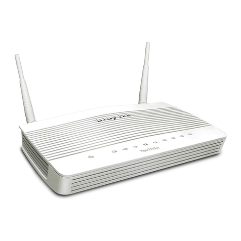
Draytek Vigor2133 Vac user guide

Cisco
Cisco Catalyst 2924M XL Using Guide
